Thanks Micahfabulous build, almost like watching a real ship get built.
"Flying Dutchman" - Ghost Ship - OREL Russian Paper Model Build
- Thread starter mtrappett
- Start date
You are using an out of date browser. It may not display this or other websites correctly.
You should upgrade or use an alternative browser.
You should upgrade or use an alternative browser.
- Apr 5, 2013
- 13,876
- 10,216
- 228
Skinning the Hull with a couple of strips on opposite sides is so important. It prevents the model from warping and the hull stays symmetric this way. Your hull is definitely symmetric!! 

So, I had to unload my camera, and here's the latest installment of the Flying Dutchman, Ghost Ship! Ah, I like saying that! 
Now we have those strips installed on each side of the ship.
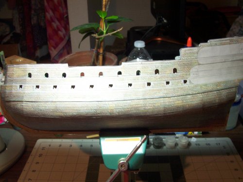
Now on to the next Milestone, which is the faces on the sides of the ship
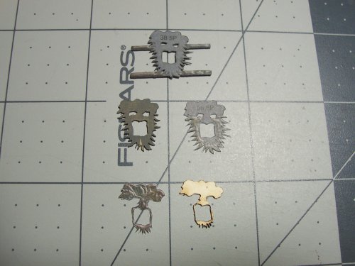
These are part numbers 38.1P-38.1L through 38.30P-38.30L. This is going to be a fair amount of work... LOL... okay, its gonna be a ton of work! There are 6 pieces per face, x 10 = 60 parts x 2 as there are L and P for the 2 ides giving a total of 120 parts for just the faces To be fair, I spread it out over a week or so of work. Its also essential I would say to replace blades frequently as soon as there are signs of dragging the edges.
This is the first card piece base for the face.
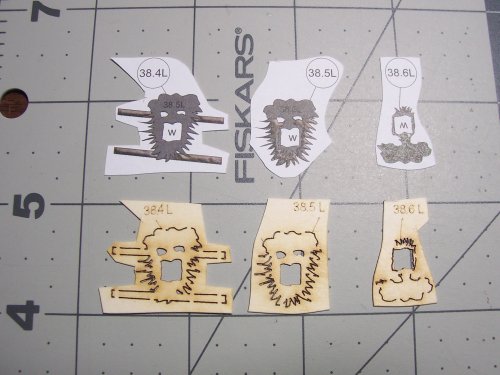
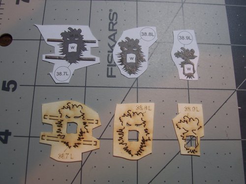
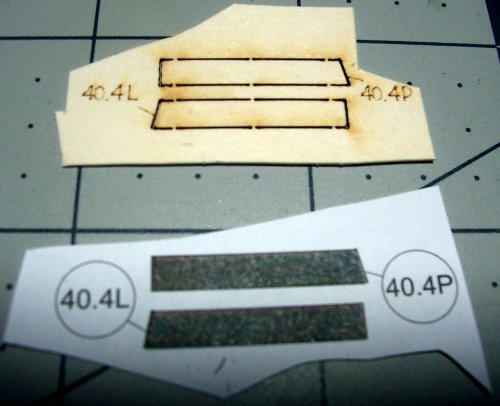
A strong tip for building the entire model which is never mentioned in the instructions (this is for the laser cut parts option) is to cut out the parts from the back of the sheet of card, the white side. This avoids having a lot of cleanup of the little areas that hold the parts in place on the card until you are ready as the line cut line is thinner and guides the blade more accurately! Also, the colored veneer parts are glued on to the front of the parts. In other words, the card side with the number details (only in the case of the laser cut option). Note the front of the part is displayed below, L is left, and P is right.
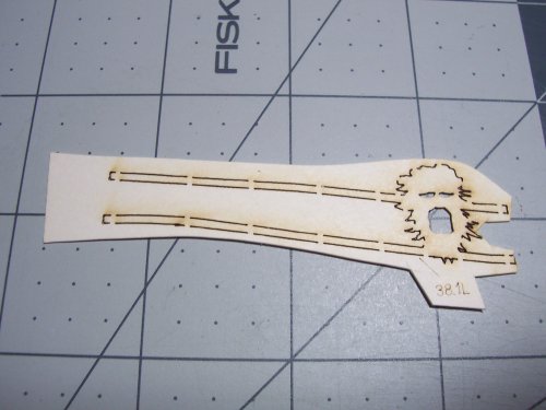
I painted the card base and the edges of the pieces to make it look nice. No lie, there is a LOT of cutting needed! The color veneer is glued on top of the card base. The 2 parts are ready to be glued together below.
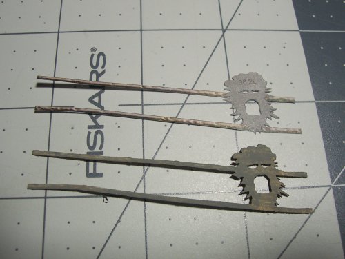
Glued successfully, and ready for the next layer!
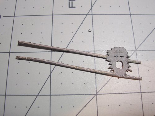
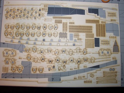
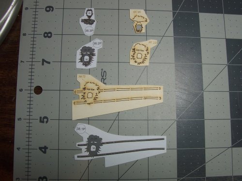
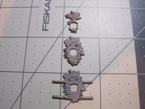
Ah yes, a broad overview of the card parts for the face pieces.
Here is the next layer, which is the face only layer.
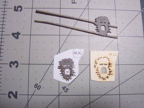
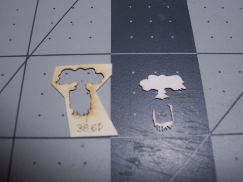
Laser cut card base on the left, and color veneer all cutout and ready on the right.
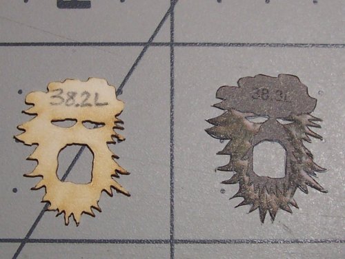
Layer number 2 ready to be glued.
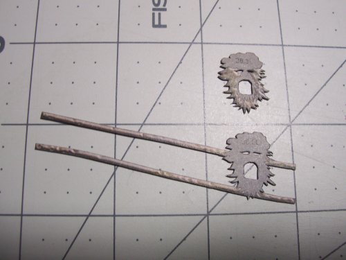
Layer 1 and 2 done.
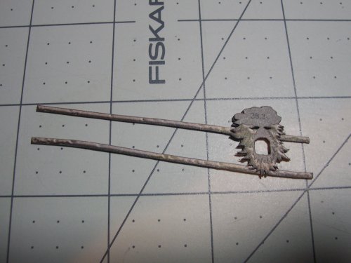
This is the third and final layer for this part.
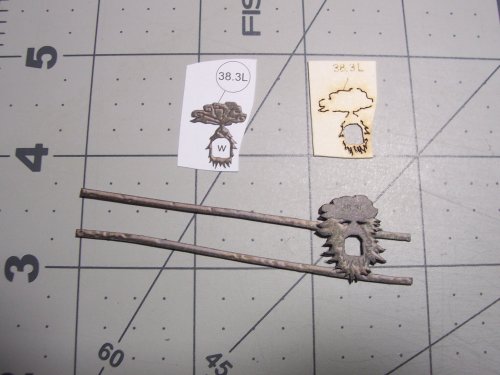
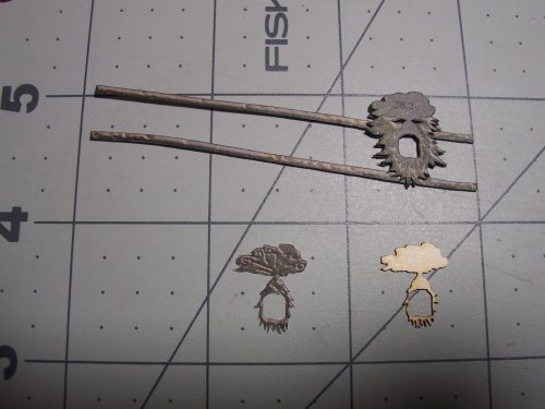
All done and ready for fitting! The faces are actually unique for each one which I think is very cool!
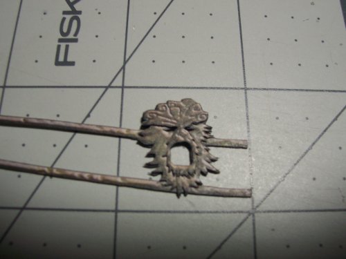
Here's another huge one for ya! The instructions never mention when and where to fit any of the cannon barrels! This is where things could get really ugly! The barrels can't be fitted if you have already installed the face on the side of the ship. It's imperative that the barrels are inserted prior to gluing them!
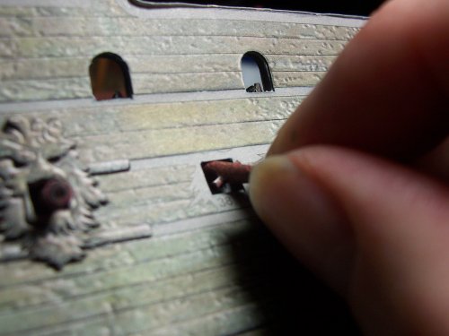
See in the picture below, the barrel barely fits through the cannon port of the face part.
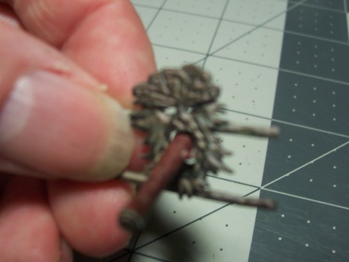
I worked on one cannon port at a time going from left of the ship to the right hand side.
Hey, the first cannon barrel glued in place! I also painted the edges of the paper with chocolate brown and added matte black for the insides of the barrel and for the blast around the entry of the barrel. This would I imagine where gunpowder soot would accumulate a bit even though the ship spends most of its time below water.
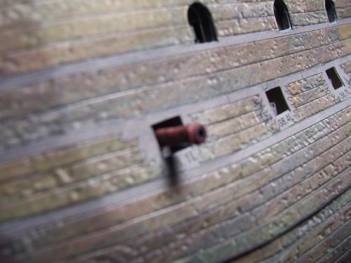
The first face in place. I glued the main body of the assembly first and then the 2 strips. I got some new "Elmer's Extreme" glue which is very strong.
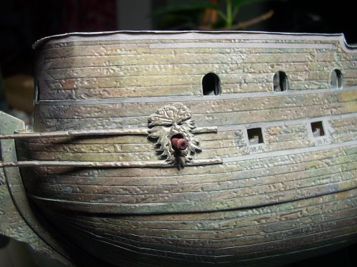
I will only show the first of these faces construction as they are the same for each, all 0 of them.
The cannon barrel has to be jiggled about a bit while finding its carriage fit location.
For God's sakes don't drop the barrel inside the hull which I think would be pretty easy to do! There's no way that would ever be fished out and would require a whole new barrel to be produced


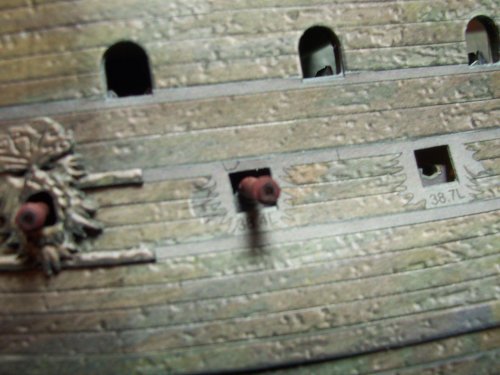
The accuracy of the fit for these is awesome! They needed no modifications at all!
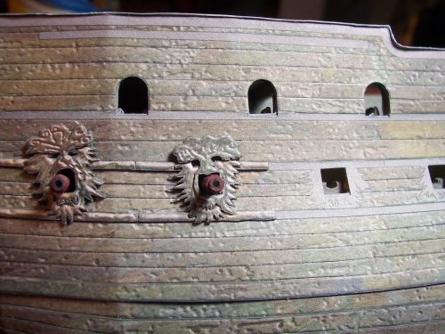
The laser cuts were too close for these pieces on a couple of them and had to be repaired a bit.

Now we have those strips installed on each side of the ship.

Now on to the next Milestone, which is the faces on the sides of the ship

These are part numbers 38.1P-38.1L through 38.30P-38.30L. This is going to be a fair amount of work... LOL... okay, its gonna be a ton of work! There are 6 pieces per face, x 10 = 60 parts x 2 as there are L and P for the 2 ides giving a total of 120 parts for just the faces
 To be fair, I spread it out over a week or so of work. Its also essential I would say to replace blades frequently as soon as there are signs of dragging the edges.
This is the first card piece base for the face.
A strong tip for building the entire model which is never mentioned in the instructions (this is for the laser cut parts option) is to cut out the parts from the back of the sheet of card, the white side. This avoids having a lot of cleanup of the little areas that hold the parts in place on the card until you are ready as the line cut line is thinner and guides the blade more accurately! Also, the colored veneer parts are glued on to the front of the parts. In other words, the card side with the number details (only in the case of the laser cut option). Note the front of the part is displayed below, L is left, and P is right.

I painted the card base and the edges of the pieces to make it look nice. No lie, there is a LOT of cutting needed! The color veneer is glued on top of the card base. The 2 parts are ready to be glued together below.

Glued successfully, and ready for the next layer!

Ah yes, a broad overview of the card parts for the face pieces.

Here is the next layer, which is the face only layer.

Laser cut card base on the left, and color veneer all cutout and ready on the right.

Layer number 2 ready to be glued.

Layer 1 and 2 done.

This is the third and final layer for this part.


All done and ready for fitting! The faces are actually unique for each one which I think is very cool!

Here's another huge one for ya! The instructions never mention when and where to fit any of the cannon barrels! This is where things could get really ugly! The barrels can't be fitted if you have already installed the face on the side of the ship. It's imperative that the barrels are inserted prior to gluing them!
See in the picture below, the barrel barely fits through the cannon port of the face part.

I worked on one cannon port at a time going from left of the ship to the right hand side.
Hey, the first cannon barrel glued in place!
 I also painted the edges of the paper with chocolate brown and added matte black for the insides of the barrel and for the blast around the entry of the barrel. This would I imagine where gunpowder soot would accumulate a bit even though the ship spends most of its time below water.
The first face in place. I glued the main body of the assembly first and then the 2 strips. I got some new "Elmer's Extreme" glue which is very strong.

I will only show the first of these faces construction as they are the same for each, all 0 of them.


The cannon barrel has to be jiggled about a bit while finding its carriage fit location.
For God's sakes don't drop the barrel inside the hull which I think would be pretty easy to do! There's no way that would ever be fished out and would require a whole new barrel to be produced


The accuracy of the fit for these is awesome! They needed no modifications at all!

The laser cuts were too close for these pieces on a couple of them and had to be repaired a bit.

Where we are currently staying, there is one of the house-managers as they are called, named Mike. He's a nice guy, and was in the Navy. He totally don't understand the need to build models though, and seemed to see everything as a dollar amount. He said, "Oh yes, well you could sell the model when its done and make some money from it... like put it on eBay or something, and then get your money back." I just agreed with him as he really doesn't understand. I like to put my entire self into what I am building, and i really don't think about the money, I think about how it would be to build the full-size ship, or wander the decks as a tiny character, and I value the details and ideas provided by others who share their opinions much more than money. My pleasure comes from those that enjoy seeing the model being built.
Anyway, LOL. Back onto the faces.
Some of the barrels are a tight squeeze and I had to flatten the backside that goes inside the ship a little bit.

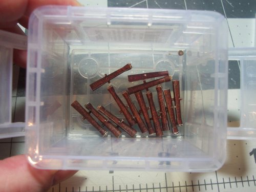
These are all the barrels I created earlier ready now for the installation.
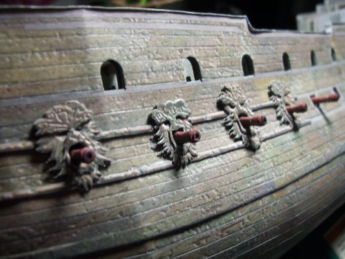
Its good to not make them all the same as that wouldn't be true to the "real" ship The carriages would have some pushed further forward, some retracted more, some at an angle and so on. That makes it looks more realistic and all.
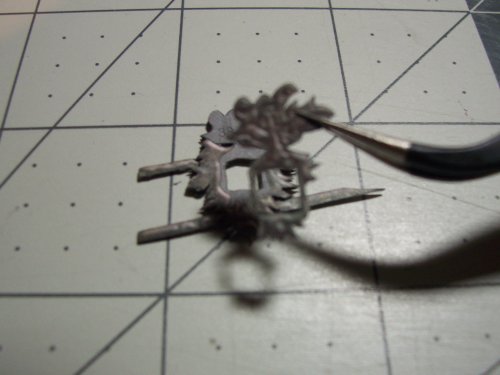
Tweezers are an essential tool for handling these small details.
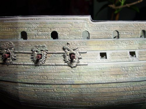
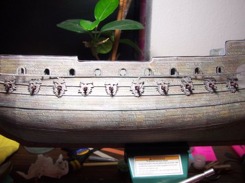
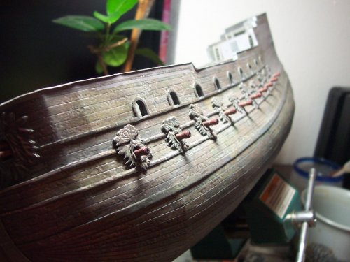
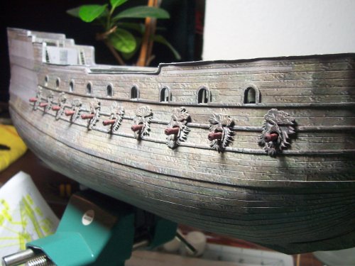
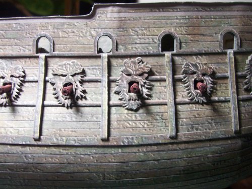
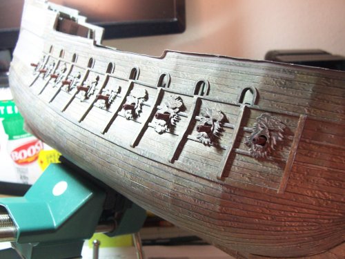
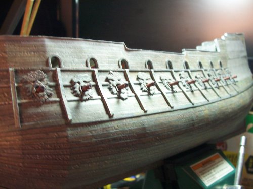
And there we are! All done and in place! You can see how accurate they all connect with one another without any cutting or modifications. I love the look of this ship! As I mentioned, you can see that each of the faces is different on the side. You can make out the shape of animals such as frogs, ducks, deer and so on... really nice.
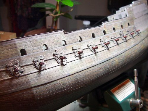
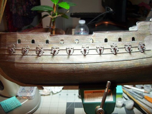
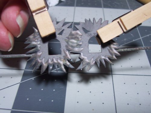
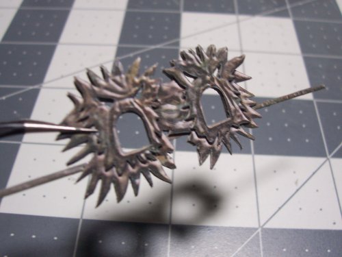
Now, moving onto the chaser cannon surrounds. I really loved working on this part! Construction is the same idea... 6 pieces.
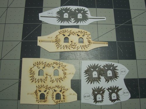
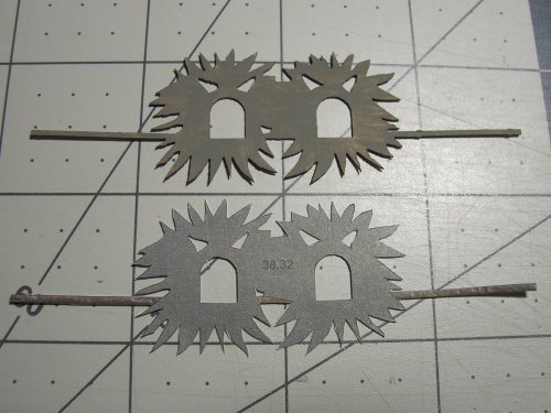
Ready to be glued together!

There was a minor fix I had to make. There are some protrusions that must be cut to allow for the front mast as I have marked below.
Ready for installation!
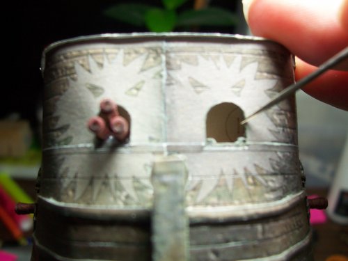
Time to install the 2 chaser cannons to the front of the ship. I covered these being built earlier.
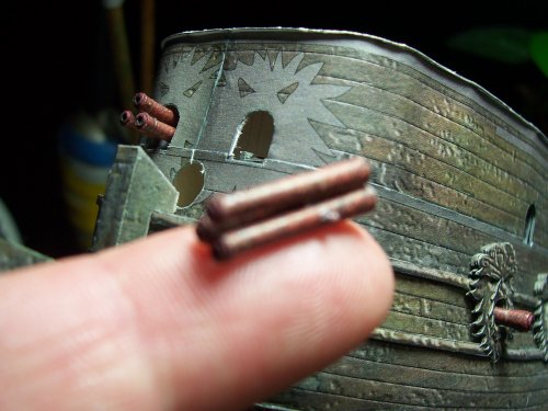
I did have to trim a bit of the edge of the ship's left cannon port to allow for the barrel to be installed (minor stuff). The barrels butt against the bulkhead anyway so they are well supported.
The finished front piece needs to be carefully bent to shape which involves bending it around a curved surface a bit at a time. Testing for fit, and bending a bit more, and so on and so forth.
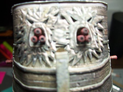
Here's the chaser cannons on the actual ship.

Anyway, LOL. Back onto the faces.


Some of the barrels are a tight squeeze and I had to flatten the backside that goes inside the ship a little bit.


These are all the barrels I created earlier ready now for the installation.

Its good to not make them all the same as that wouldn't be true to the "real" ship
 The carriages would have some pushed further forward, some retracted more, some at an angle and so on. That makes it looks more realistic and all.
Tweezers are an essential tool for handling these small details.

And there we are! All done and in place! You can see how accurate they all connect with one another without any cutting or modifications. I love the look of this ship! As I mentioned, you can see that each of the faces is different on the side. You can make out the shape of animals such as frogs, ducks, deer and so on... really nice.


Now, moving onto the chaser cannon surrounds. I really loved working on this part! Construction is the same idea... 6 pieces.


Ready to be glued together!

There was a minor fix I had to make. There are some protrusions that must be cut to allow for the front mast as I have marked below.

Ready for installation!

Time to install the 2 chaser cannons to the front of the ship. I covered these being built earlier.

I did have to trim a bit of the edge of the ship's left cannon port to allow for the barrel to be installed (minor stuff). The barrels butt against the bulkhead anyway so they are well supported.

The finished front piece needs to be carefully bent to shape which involves bending it around a curved surface a bit at a time. Testing for fit, and bending a bit more, and so on and so forth.

Here's the chaser cannons on the actual ship.

Cannons
Two of the Dutchman's cannon ports.
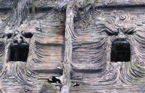
The Flying Dutchman's cannon's emerged from ports on either side of the ship. The ports were carved into the hull and took the forms of sea demons with wide gaping mouths, when the curse on the ship was broken the cannon ports appear to be carvings of animal heads like lions and fish made of gold or bronze.
The Dutchman's main armament consists of twenty 36-pound cannons and eighteen 24-pound cannons, supplemented by 3-pounders on the quarterdeck and forecastle, making her capable of delivering a 588 lb. broadside. This overwhelmingly heavy broadside proves on multiple occasions to be a destructive, if not fatal, blow to any ship that is at range of this powerful ship. It also carries two large triple rotating bow chasers.
The prow of the ship resembled a fanged mouth, and featured a carved figurehead resembling the Grim Reaper and his scythe, while the un-corrupted prow looked like a head of a crocodile\barracuda with wooden spikes resembling razor-sharp teeth and no figurehead.
In addition, the Dutchman's sails were white, but raggedy, and covered with seaweed and grime, with multiple holes, perhaps from the many trips into the ocean's depths, but when the curse was broken the sails kept their damaged appearance though they lost the seaweed and grime covering them.
Overall the Dutchman carries 46 cannons, considering her primary weapons were 24-pounders and 36-pounders, the Dutchman was perhaps one of the most powerful ships in the Caribbean.
Reference:
(From POTC Wiki Web Site)
________________________________________________________________________________________________________________________
Next, is the surround for the upper cannon ports. The cannons fit through these okay, so no need to fit them yet. I think its better to leave the installation of the cannon barrels as late as possible as they have the potential for getting in the way of the other stuff that needs to be fitted.
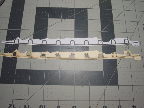
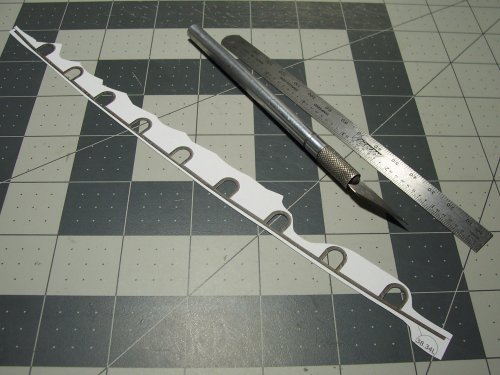
I started from the middle of the window surround piece to allow for any possible inaccuracies being spread more evenly from front to back.
Left side upper cannon port surround done.
... and the right side upper cannon port surround installed.
Now onto the vertical supports (not sure what their real name might be?".

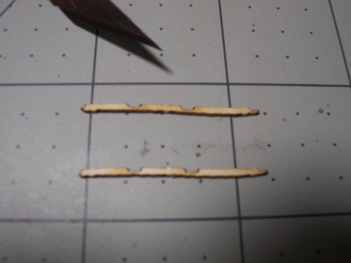
Each piece is comprised of 2 parts glued together to get the right thickness.
The first one installed.
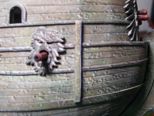
Two of the Dutchman's cannon ports.

The Flying Dutchman's cannon's emerged from ports on either side of the ship. The ports were carved into the hull and took the forms of sea demons with wide gaping mouths, when the curse on the ship was broken the cannon ports appear to be carvings of animal heads like lions and fish made of gold or bronze.
The Dutchman's main armament consists of twenty 36-pound cannons and eighteen 24-pound cannons, supplemented by 3-pounders on the quarterdeck and forecastle, making her capable of delivering a 588 lb. broadside. This overwhelmingly heavy broadside proves on multiple occasions to be a destructive, if not fatal, blow to any ship that is at range of this powerful ship. It also carries two large triple rotating bow chasers.
The prow of the ship resembled a fanged mouth, and featured a carved figurehead resembling the Grim Reaper and his scythe, while the un-corrupted prow looked like a head of a crocodile\barracuda with wooden spikes resembling razor-sharp teeth and no figurehead.
In addition, the Dutchman's sails were white, but raggedy, and covered with seaweed and grime, with multiple holes, perhaps from the many trips into the ocean's depths, but when the curse was broken the sails kept their damaged appearance though they lost the seaweed and grime covering them.
Overall the Dutchman carries 46 cannons, considering her primary weapons were 24-pounders and 36-pounders, the Dutchman was perhaps one of the most powerful ships in the Caribbean.
Reference:
(From POTC Wiki Web Site)
________________________________________________________________________________________________________________________
Next, is the surround for the upper cannon ports. The cannons fit through these okay, so no need to fit them yet. I think its better to leave the installation of the cannon barrels as late as possible as they have the potential for getting in the way of the other stuff that needs to be fitted.


I started from the middle of the window surround piece to allow for any possible inaccuracies being spread more evenly from front to back.

Left side upper cannon port surround done.

... and the right side upper cannon port surround installed.

Now onto the vertical supports (not sure what their real name might be?".

Each piece is comprised of 2 parts glued together to get the right thickness.

The first one installed.

THE DC
Highly Esteemed Member
Breath taking!
I have got to find this kit!
Is it a Russian design or was it from a Polish company?
I have got to find this kit!
Is it a Russian design or was it from a Polish company?
I light the cannon ports. They turned out nicely! I like how they look!
I fully sympathize with you about your situation with the "House-Manager". I have ran into many people like that. They have no real understanding and appreciation of this hobby and all of the time, effort, energy, and work that is invested in any given project.
KEEP UP THE GREAT WORK!!!
I fully sympathize with you about your situation with the "House-Manager". I have ran into many people like that. They have no real understanding and appreciation of this hobby and all of the time, effort, energy, and work that is invested in any given project.
KEEP UP THE GREAT WORK!!!
No one in my family understands why I do any of my hobbies. Well, they understand why I play D&D, but not everything else I do related to that. Mind blowing work on this ship. It looks to be a fabulous kit.


OK, this is killer - and a sticky now.


THE DC
Highly Esteemed Member
No one in my family understands why I do any of my hobbies. Well, they understand why I play D&D, but not everything else I do related to that. Mind blowing work on this ship. It looks to be a fabulous kit.
That's worth a saving throw...
Thank you!Breath taking!
I have got to find this kit!
Is it a Russian design or was it from a Polish company?
It's been pretty crazy since the last time I posted, but I have been working on the vessel as much as possible.
These are the vertical pieces that run along the sides of the ship. There are a lot of parts for these. Each one is constructed from 4 parts that are typically like the ones shown below
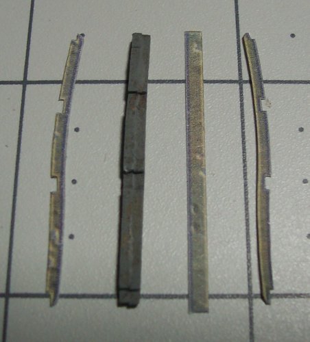
Here's a couple of them fitted. The verticals hide the joints in the horizontals.
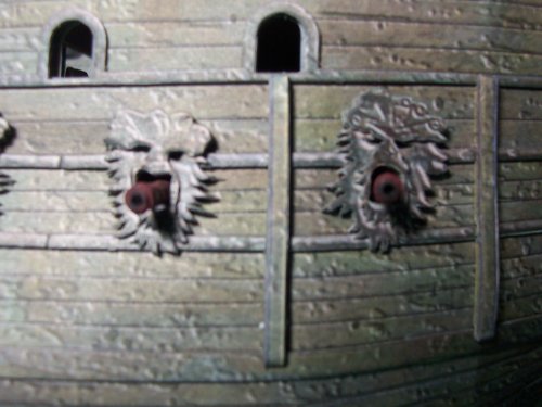
Here's a view of the contoured shape after the card pieces have been assembled.
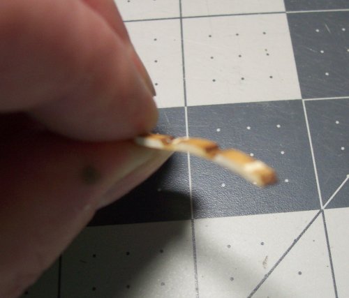
You get the idea... here's four of them installed. Each are a little different in shape.
That's all the right side vertical pieces installed. They fit perfectly between the horizontals.
Left side done. There's another milestone as there is a LOT of work in getting these done.
These are the edge pieces that go from front to rear of the ship.
This is one that I laminated together and is ready to be fitted.

Here it is successfully fitted on the right side. Best to just do a little at a time.
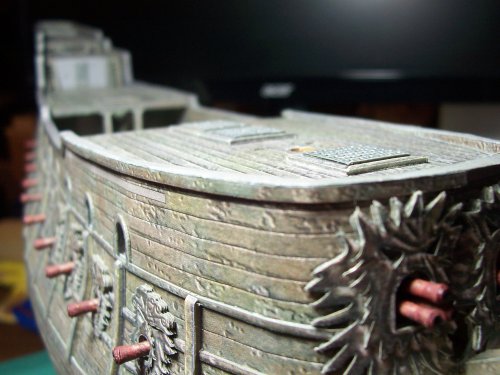
A view of the fitting of the edge parts on the right side, rear. No issues with the shape, and they fit perfectly.
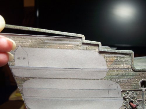
Now working on the left side. The edge strips level the overlapping parts above.
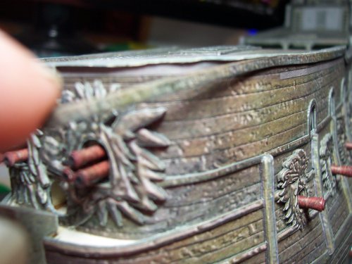
The long horizontal edge fitted on the left, port side.
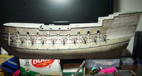
A rear view of the edging installation completed.
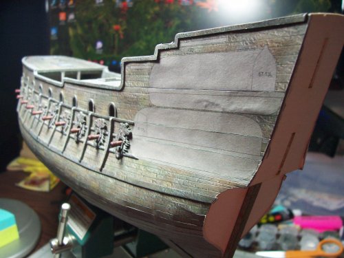
The edging wraps-around the bow as can be seen here.
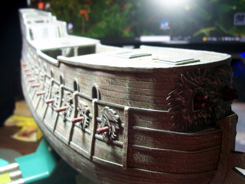
Starting work on the transom of the ship.
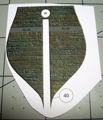
The ship has a pleasing shape to the stern. The keel is very thick and sturdy. It is necessary to do some smoothing with the scalpel and sanding block to get the edges nice and accurate for the rest of the transom parts.
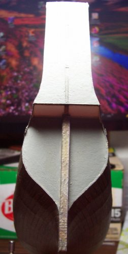
A view of the work that needs to be done.
Starting to look nice
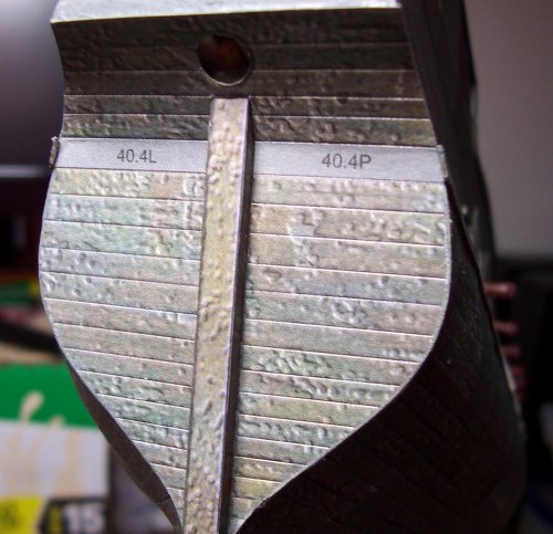
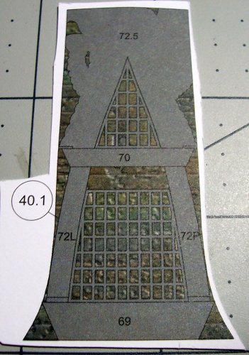
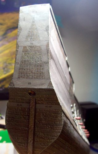
The Windows for the galley. This is where they will be fitted.
These are the vertical pieces that run along the sides of the ship. There are a lot of parts for these. Each one is constructed from 4 parts that are typically like the ones shown below

Here's a couple of them fitted. The verticals hide the joints in the horizontals.

Here's a view of the contoured shape after the card pieces have been assembled.

You get the idea... here's four of them installed. Each are a little different in shape.

That's all the right side vertical pieces installed. They fit perfectly between the horizontals.

Left side done. There's another milestone as there is a LOT of work in getting these done.

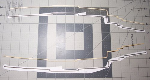
These are the edge pieces that go from front to rear of the ship.

This is one that I laminated together and is ready to be fitted.

Here it is successfully fitted on the right side. Best to just do a little at a time.

A view of the fitting of the edge parts on the right side, rear. No issues with the shape, and they fit perfectly.

Now working on the left side. The edge strips level the overlapping parts above.

The long horizontal edge fitted on the left, port side.

A rear view of the edging installation completed.

The edging wraps-around the bow as can be seen here.

Starting work on the transom of the ship.

The ship has a pleasing shape to the stern. The keel is very thick and sturdy. It is necessary to do some smoothing with the scalpel and sanding block to get the edges nice and accurate for the rest of the transom parts.

A view of the work that needs to be done.

Starting to look nice

The Windows for the galley. This is where they will be fitted.


Continuing on with the transom detail including the windows for the gallery.
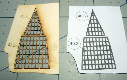
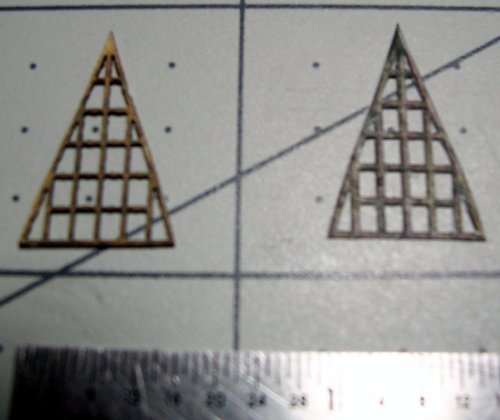
I bought a pack of 100 blades for my X-Acto knife, and I'm about half-way through them. Time to install a new blade for this! Make sure to have a steady hand for making all the tiny cuts in the paper on the right image.
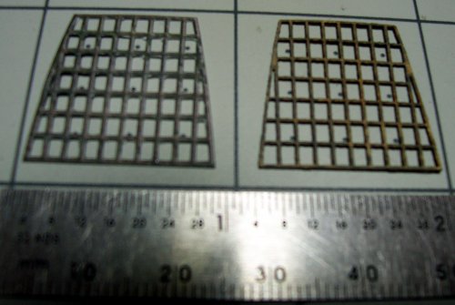
These are ready to be joined.
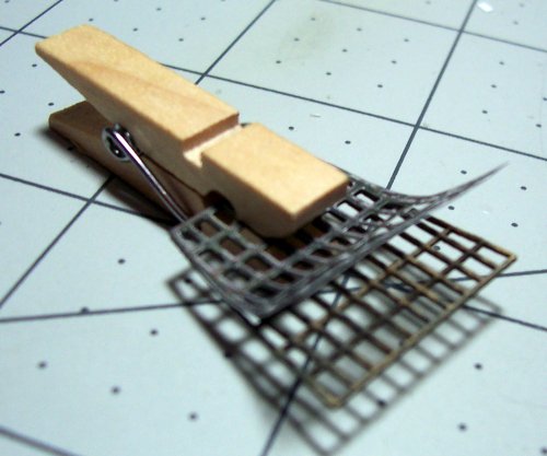
I found the most accurate way of bonding the card with the color veneer is to use a tiny peg to hold them in exactly the right place then apply the glue to one side, then the other.
Looking nice!
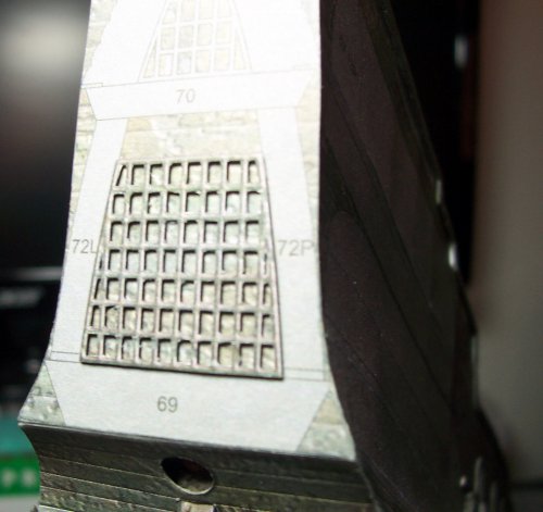
This is the top portion of the Gallery window frame.
Fitted to the rear of the ship. Be sparing with the glue.
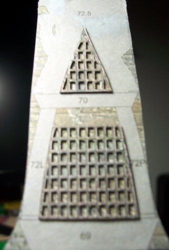
This is a section of the rear siding.
This is the installation of the small right side panel.
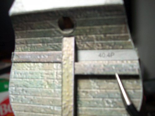
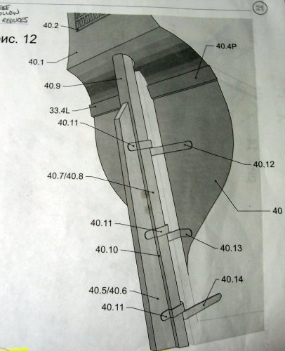
Moving onto the steering blade. Parts 40.11 through 40.14 are the hinges by the way.
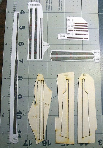
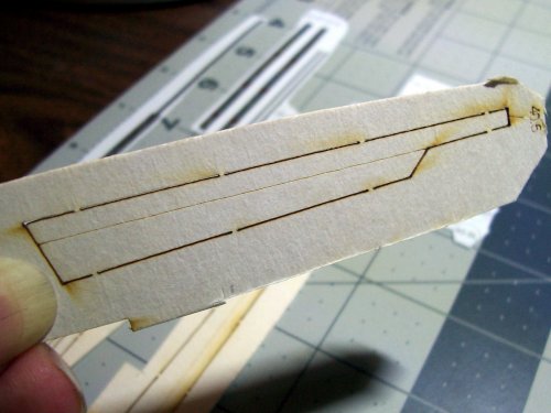
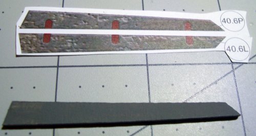
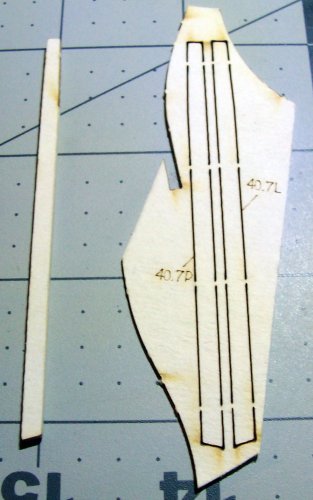
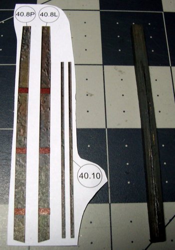
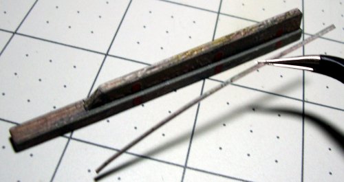
The brown marked areas are where the hinges will be placed.
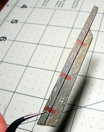
On the left is the color veneer that will go all the way around the edge.
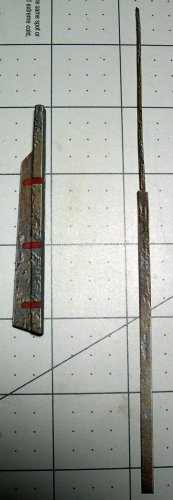
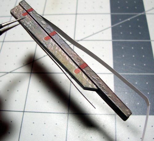
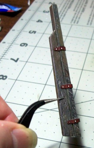
This is the fitting of the hinges in place on the steering blade.
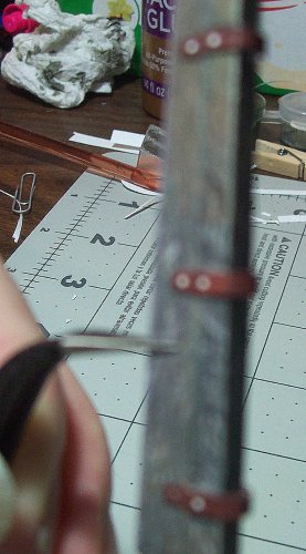
Is it just my eyes, or is this like totally blurred?


I bought a pack of 100 blades for my X-Acto knife, and I'm about half-way through them. Time to install a new blade for this! Make sure to have a steady hand for making all the tiny cuts in the paper on the right image.

These are ready to be joined.

I found the most accurate way of bonding the card with the color veneer is to use a tiny peg to hold them in exactly the right place then apply the glue to one side, then the other.

Looking nice!

This is the top portion of the Gallery window frame.

Fitted to the rear of the ship. Be sparing with the glue.

This is a section of the rear siding.

This is the installation of the small right side panel.

Moving onto the steering blade. Parts 40.11 through 40.14 are the hinges by the way.


The brown marked areas are where the hinges will be placed.

On the left is the color veneer that will go all the way around the edge.


This is the fitting of the hinges in place on the steering blade.

Is it just my eyes, or is this like totally blurred?


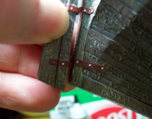
The steering blade is fixed and does not turn. I did have to re-shape the top to match the "hole" the shaft fits into.
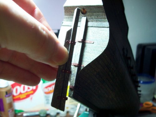
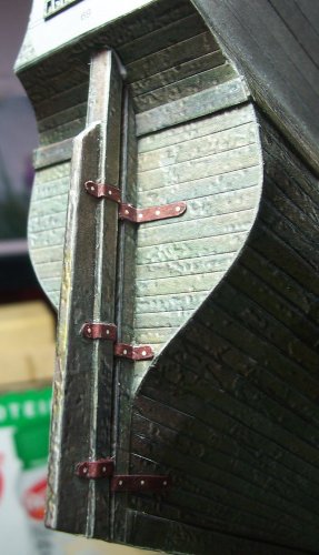
The hinges look pretty good. I decided to use the hinges supplied with the actual model instead of the brass etched parts.
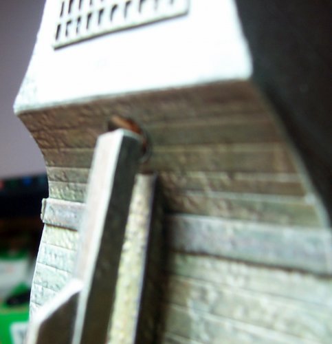
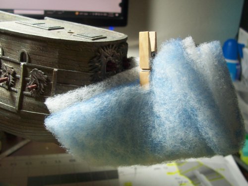
It seems that the bow is vulnerable to damage, so I used a bit of padding to keep it protected.
The glue's still wet I'm happy with the way the steering blade came out.
This is for the bow to cover the plain panel.
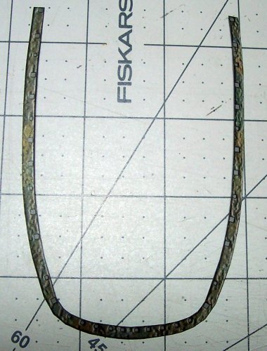
It fits really well.
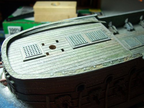
These pieces cover the sides.

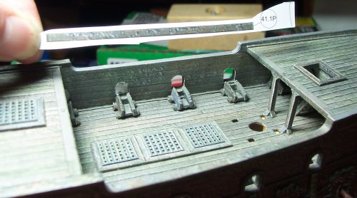
These also fit really well.
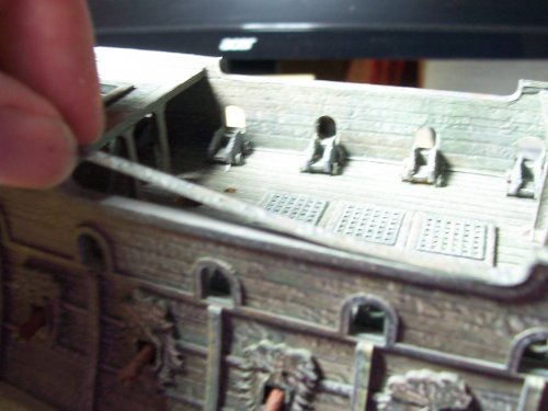
The upper deck sides.

Milestone: Start of the Ships Railings


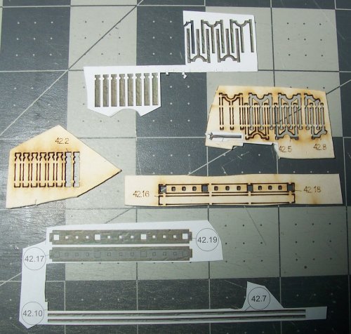
This shows how to build the front railing section. Note that this is a difficult part.
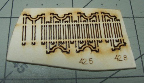
A couple of the card bodies pf railings ready for use.
These are the ornate sections.

The hinges look pretty good. I decided to use the hinges supplied with the actual model instead of the brass etched parts.


It seems that the bow is vulnerable to damage, so I used a bit of padding to keep it protected.

The glue's still wet

This is for the bow to cover the plain panel.

It fits really well.

These pieces cover the sides.


These also fit really well.


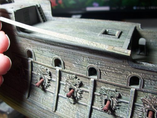
The upper deck sides.


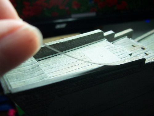
Milestone: Start of the Ships Railings


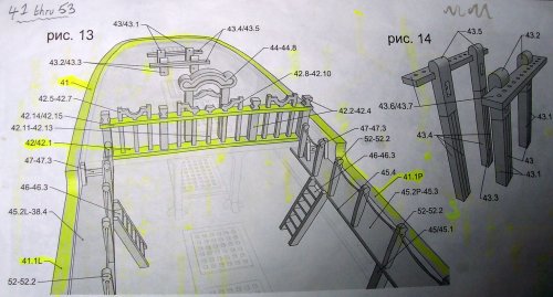
This shows how to build the front railing section. Note that this is a difficult part.

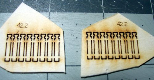
A couple of the card bodies pf railings ready for use.

These are the ornate sections.

This is an extremely detailed model so I am finding out, and is posing a challenge for sure!
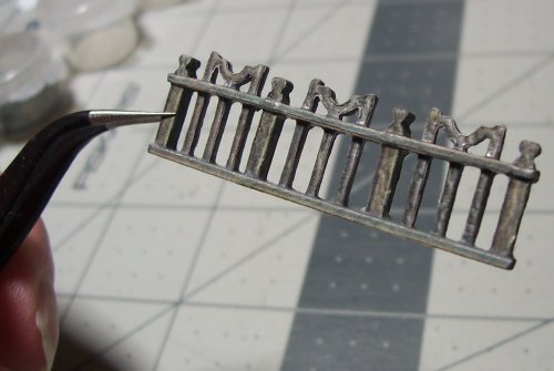
These are very delicate parts and can be easily damaged inadvertently by rough-handling. I found the best way to install the curved fancy pieces was to first glue the card parts, and then cut and glue the color veneers. It is way too difficult to slide the completed railing through the square hole. The railing becomes too thick after it has had its veneer glued on.
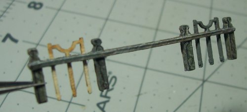
Yes, its finished
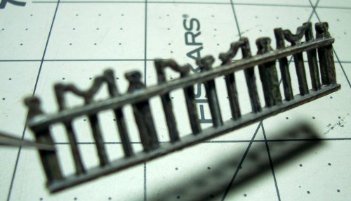
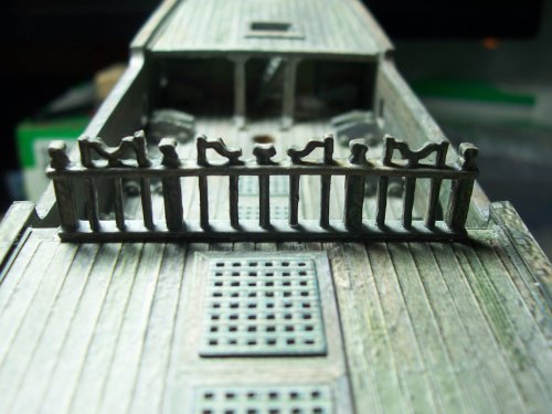
Here it is glued in position on the deck. Be sure not to follow the marking on the deck otherwise it will be offset to one side! Not good and it will look funky!
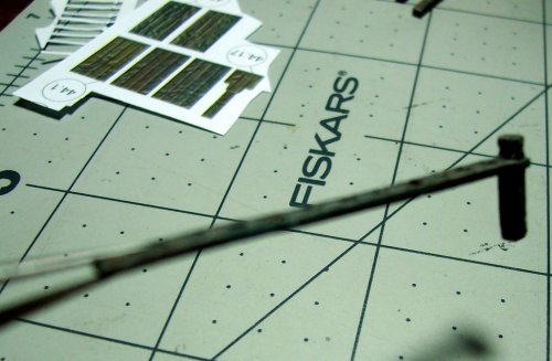
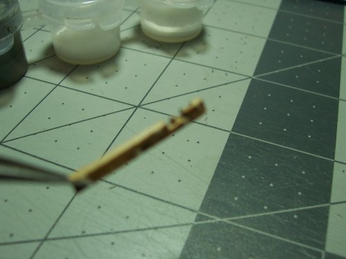
I used a air drill to open up the holes in the paper veneer. Just use the fingers and not a Dremel as the drill bit will try to drift off to the side. These holes will be for the rigging eventually that will go up to the sails and masts amongst other things.
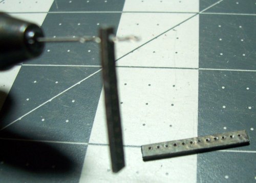
These are too long and will stick up as they are. They need to be slightly trimmed so they are at the correct depth.

The square holes are very accurately cut. The parts slide in really nice.
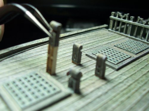
This is the "Bridge" one for the front and one for the back. The back one has been purposely designed to look like it took some battle damage.
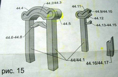
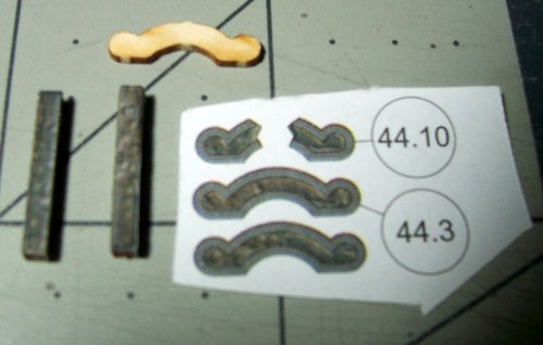
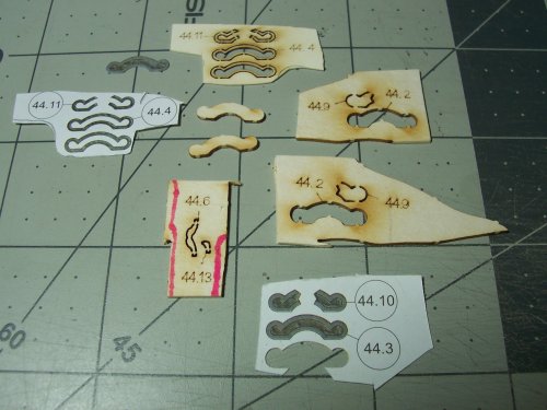
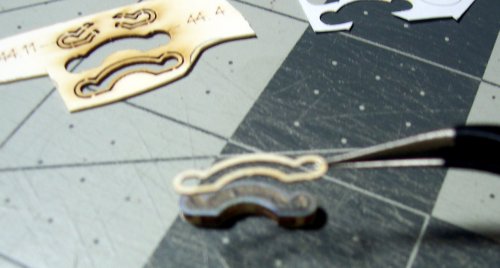
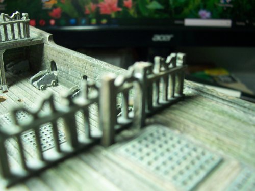
These are very delicate parts and can be easily damaged inadvertently by rough-handling. I found the best way to install the curved fancy pieces was to first glue the card parts, and then cut and glue the color veneers. It is way too difficult to slide the completed railing through the square hole. The railing becomes too thick after it has had its veneer glued on.

Yes, its finished


Here it is glued in position on the deck. Be sure not to follow the marking on the deck otherwise it will be offset to one side! Not good and it will look funky!


I used a air drill to open up the holes in the paper veneer. Just use the fingers and not a Dremel as the drill bit will try to drift off to the side. These holes will be for the rigging eventually that will go up to the sails and masts amongst other things.

These are too long and will stick up as they are. They need to be slightly trimmed so they are at the correct depth.

The square holes are very accurately cut. The parts slide in really nice.

This is the "Bridge" one for the front and one for the back. The back one has been purposely designed to look like it took some battle damage.


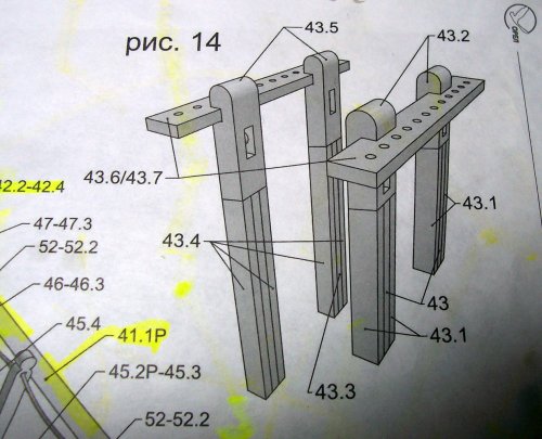
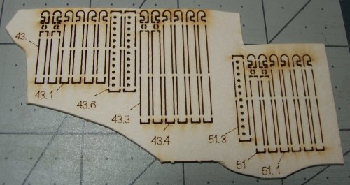
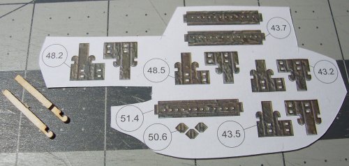
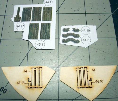
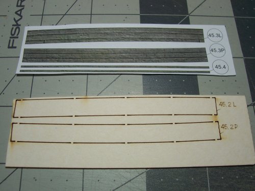
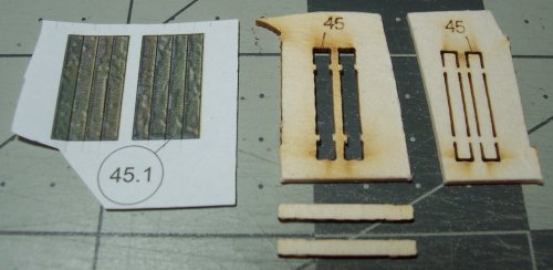
One thing that is not mentioned in the instructions is the sequence of building the model, it goes X.Y where X is the main assembly number to work on, and Y is the sub component of that assembly. It's extremely important to get a grasp early on about this. For example, the following part is the broken bridge assembly. This is part 44. Each of the smaller pieces or color veneers are 44.1, 44.2 and so on.
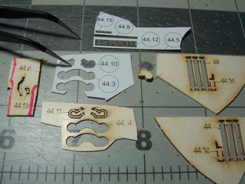
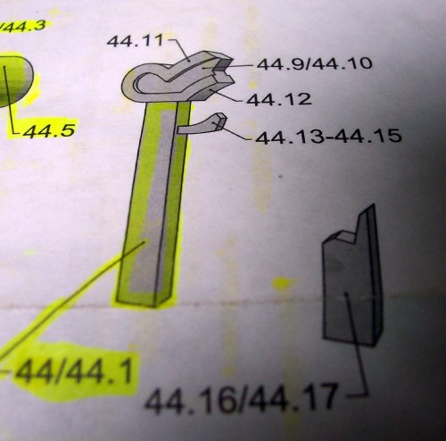
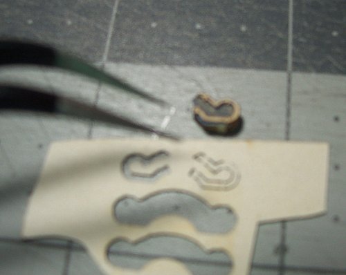
Very small stuff.
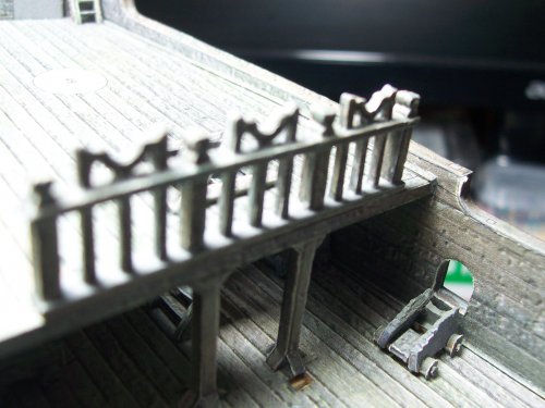
You get a decent view of the 2 railings and 2 bridges
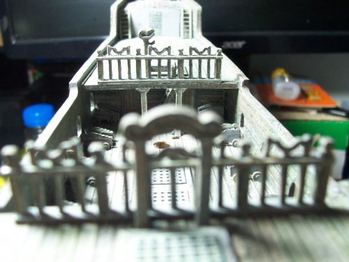
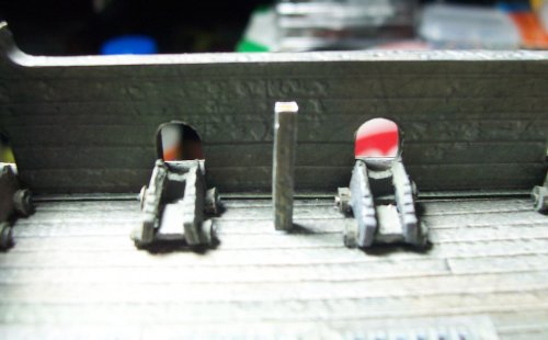
Adding the side-decks for the dudes to run along. This is the support post.
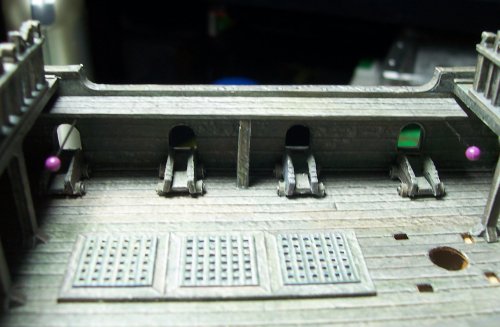
Deck in place. Its a bit tricky to get positioned right, so I uses a couple of pins as rests.
The Ladder sides.
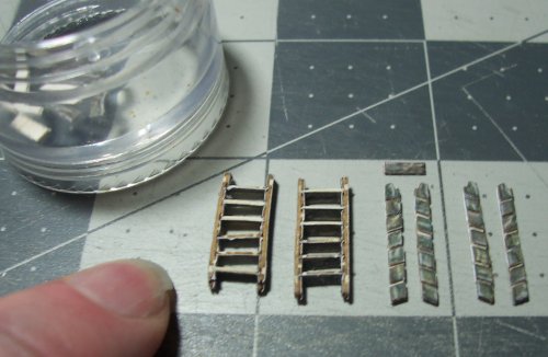
These are for the lower deck to the side decks.
Tack it in place to start with at the front.
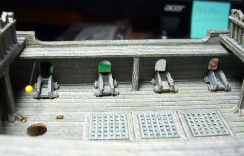
I cut a couple of color veneers for the long sides of the ladders from the spare section as they are not provided.
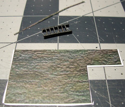


Very small stuff.


You get a decent view of the 2 railings and 2 bridges

Adding the side-decks for the dudes to run along. This is the support post.

Deck in place. Its a bit tricky to get positioned right, so I uses a couple of pins as rests.

The Ladder sides.

These are for the lower deck to the side decks.

Tack it in place to start with at the front.

I cut a couple of color veneers for the long sides of the ladders from the spare section as they are not provided.

Last edited:

