Razor Crest from Mandalorian / Roland Tari

MikeBer

Active Member
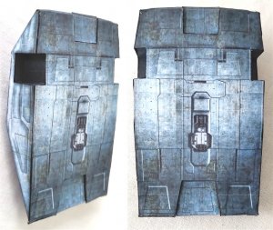
This is part of the rear landing unit printed on A4 which I practised with to get the feel of the build.
I will start by printing out the parts on plain paper just to check the fit, correct tab locations and method of assembly. Once satisfied I will number the parts and then start to build in modules.
 

Attachments

  • Landing unit.jpg
    Landing unit.jpg
    257 KB · Views: 18

zathros

*****SENIOR ADMINISTRATOR*****
Staff member
Administrator
Moderator
I have decided to start this model again and I will publish my progress as I go along.
As a first step, I opened up each pdf page in GIMP and then saved them individually as page 1 to 8 Bitmap files. Then, one at a time, I opened up each page in MS Paint and copied the parts one by one and pasted them onto new A4 sized pages. Some of the parts were too big so I divided them into 2 pieces. I ended up with 13 x A4 sized pages.
I have also decided to number each part to make assembly easier.
The main problem that I found previously was the tab positions so I have started to relocate them on the drawings to make assembly easier.
As I build, I will fine tune the parts and then upload the relevant pages to Mediafire as they are completed.


Great idea!! :)
 

MikeBer

Active Member
This is a very well designed model but unfortunately the parts were printed in A3 format.
Because the majority of modellers only have an A4 printer, including myself, I’ve re-arranged the parts (without a reduction in scale), to fit onto A4 sized sheets.
4 of the parts were too big to fit onto A4 sheets so I divided each of the 4 parts into 2 pieces each, using panel lines for the joining interfaces.

Another thing that I was not happy with was the tab positions. As a personal preference, I don’t like tabs to alternate between two parts as I feel that this gives rise to “wavy” join lines. I prefer the tabs to all be on the one part so that a clean straight join is obtained.

The assembly guide of the original model only consisted of pictures with no discernible sequence or part numbering so I have numbered all the parts on the A4 sheets, using a modular numbering system.

The model was well designed to be built in modules, so I’ve kept to this, starting with the main body (B).

As a personal preference, I find it easier to scribe all parts that bend before cutting them out.

Once I am satisfied with each module, I will upload the relevant pdf pages to Mediafire for you to download should you wish to build it.
 

MikeBer

Active Member
Main body.

Join the base parts B to Ba and then re-enforce base B with 1mm card using the template guide provided.

Photo 01.jpg

Assemble parts B3a & B4a and when dry, fit them to sides B3 & B4. Note that there is an alignment dot on one of the tabs on each part. This tab faces the front of the body.

Photo 02.jpg

Using cereal box card, reinforce sides B3, B4 and part Ba as shown, leaving room for the base tabs at the bottom.

Photo 03.jpg

Join sides B3 & B4 to base B.

Photo 04.jpg

Join parts B1 to B2 and then to Base B and sides B3 & B4.

Photo 05.jpg

Rear landing unit.

After assembling parts L1a, L1b, L1c & L1d, glue them to part L.

Photo 06.jpg

Now attach sides L2 & L3 to L.

Photo 07.jpg

Note that the front and rear bend slightly.

Photo 08.jpg

Add reinforcing card.

Photo 09.jpg

Now attach this unit to the body.

Photo 10.jpg

This completes module 1. The files can be found here :-

http://www.mediafire.com/folder/e2cv2r9jdye20/Razor_Crest

Please feel free to tell me if you pick up any problems or mistakes.
 
Last edited:

Rhaven Blaack

!!!THE MAN BEHIND THE CURTAIN!!!
Staff member
Administrator
Moderator
Thank you for posting this thread! It is going to be very helpful to all who build this model.
I like how this is taking form! You are doing a great job on it! I can see that there is a great deal of greebling potential.
 

zathros

*****SENIOR ADMINISTRATOR*****
Staff member
Administrator
Moderator
This will be the go to thread for building this model. Also, that Stagecoach on your Blog is fantastic!! :)

Side%2Bview.jpg
 

MikeBer

Active Member
There is a modification to part TB2 on the Page 2 pdf. The new version is uploaded but will not affect the construction of module 1.
 

MikeBer

Active Member
Upper body (Module 2).

Attached T to T1 and then glue on the card stiffeners.
Photo 01.jpg

Join parts TB2 to TB3 and TB4 to TB5.
Photo 02.jpg

Add card stiffeners to these assemblies.

Construct part TB7a and attach to part TB7.
Photo 03.jpg

Construct part TB7b as shown.
Photo 04.jpg

Now, attach TB7b to part TB7 by initially gluing the tabs as shown in RED.
Photo 05.jpg

Wait until completely dry and then glue the rest of the tabs around the underneath of TB7b.
Photo 06.jpg

Attach TB7e to TB3 and then attach TB7.
Photo 07.jpg

Repeat for TB7f, TB5 & TB7.
Photo 08.jpg

Now attach this assembly to T1.
Photo 09.jpg

When dry, continue to attach this assembly to the base T, one tab at a time.
Photo 10.jpg

Attach pieces TB7c & TB7d to TB6 (Note the raised edges).
Photo 11.jpg

Attach card stiffeners to TB6 and then glue TB6 to TB7.
Photo 12.jpg

Glue TB6a to TB6 and when dry attach to TB2 & TB4.
Photo 13.jpg

Photo 14.jpg

This completes module 2.
When dry, the two modules were joined together.
Photo 15.jpg

The files can be found here:-
http://www.mediafire.com/folder/e2cv2r9jdye20/Razor_Crest

Next step is the cockpit and front landing unit.............
 
Last edited:
Top