

The awning you can make by cutting out paper squares. Now you have the base of the awning the ribs will be verry small 1 or 1.5 mm. Make sure you have two or more pieces. Now you can glue clear thin plastic blister packige on the ribs. Take the second base and glue it on the plastic. For stifnes you can use some layers.
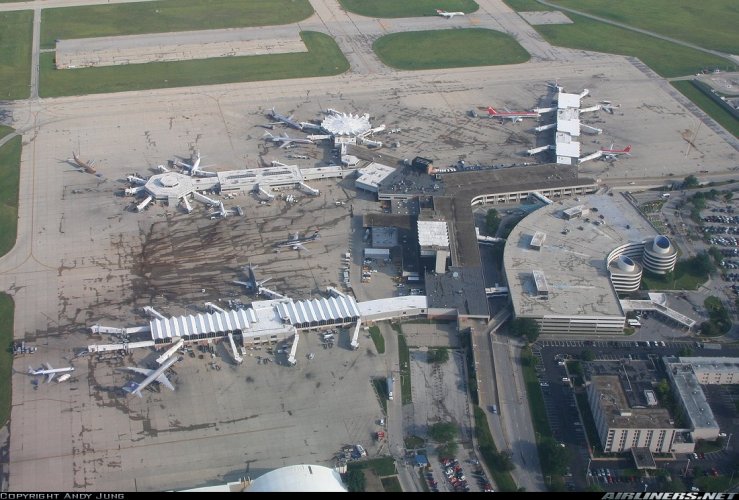
Indianapolis International Airport in 1:400
- Thread starter IndyJets
- Start date
You are using an out of date browser. It may not display this or other websites correctly.
You should upgrade or use an alternative browser.
You should upgrade or use an alternative browser.

Very good point about allowing for the paper thickness. Is there a reference table anywhere that lists the dimensional thickness in terms of paper weight?
It is important to know that paper weight does not equal paper thickness. Of course heavier paper can be thicker than normal paper but depending on the manufacturer there might be differences. The easiest way to find out how thick one sheet of paper is this: You take a number of sheets, count how many of them there are, put them on top of each other to form one solid paper block, measure the thickness of the block and divide it by the number of sheets used. That gives you the thickness of one page. Another way would be using calipers.
Also how much extra backing do I need to add in order to get a good effect in 1:400 scale? I'm thinking I might also apply this same technique on the double-deck covered roadway along the front of the terminal itself (which faces the parking garage across the arrivals roadway).
That depends on your personal preference. I would make a small mockup to check everything out. If you are pleased with it, go with it. If not, make some changes till it looks good. There is no one and only way to do it, there is no right and no wrong. All that matters is your decision how complex you want to go with it and your personal preference.
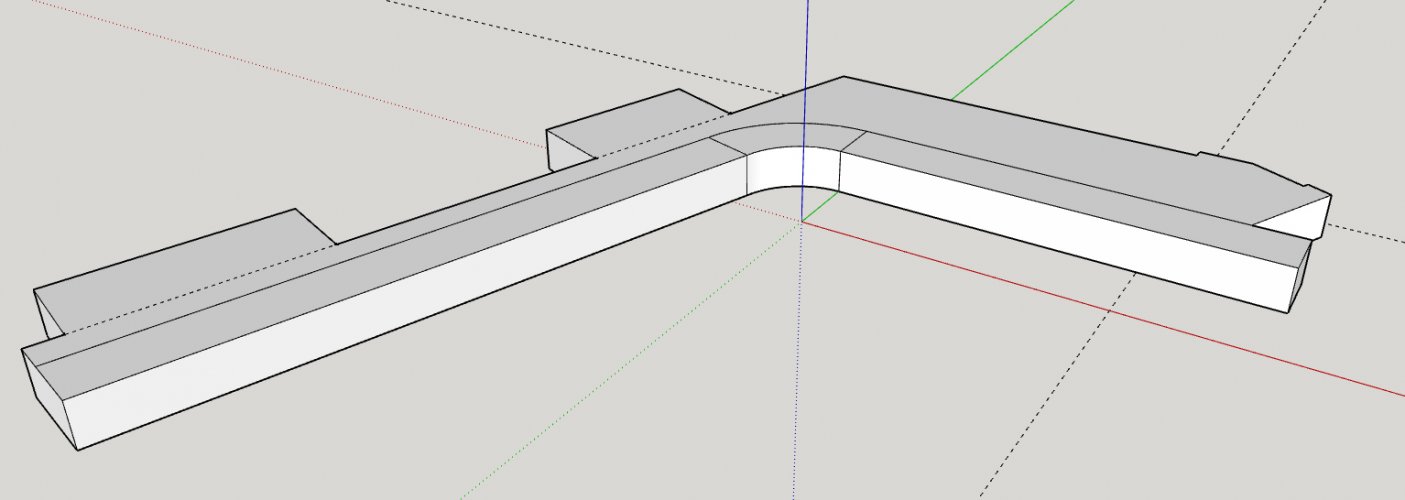
Something I noticed is that the curves on the original consist of a series of straight bars which are assembled in a row at a constant angle. This is exactly the way a 3D program forms curves. You could make advantage of it. Those tiny edges may be used as natural folding / cutting lines on the model:

The red lines represent the edges forming the curve. Everything with the same colour is a straight face. This little trick can be used to acurately place the coloumns, too. They should be on each red line.
Would I necessarily need to go through the trouble of making a separate Sketchup model for each layer of material or could I get by with making duplicates of the face shapes in Inkscape then trimming away the edges to allow for the thickness of the overlying layer(s)?
Again, personal preference. Since you are dealing mostly with straight faces you can edit the unfold in InkScape later. Using SketchUp might be easier since you don't have to fiddle with the lines later. But that is just my opinion. Yours may be different.
") Just make a small mockup and toy with it to see what is best for you.
Just make a small mockup and toy with it to see what is best for you. ")
BTW, just in case you haven't got it yet, you're gonna need THIS:
GitHub - skotekar/flattery: Sketchup Plugin for Unfolding or Flattening Models - Works in Sketchup 2016
Sketchup Plugin for Unfolding or Flattening Models - Works in Sketchup 2016 - skotekar/flattery
 github.com
- Apr 5, 2013
- 13,876
- 10,214
- 228
Don't know how I missed that. It's a big spread thougj, so he will ha e to select the sttru tures he wants. I don't know if the REIL' S changed (Runway End Illimination Lights) or if he is including them. I guess Indy zJets will have to selct buildings and maybe members van help him out. Thanks Awry!!!!!
I'm only going to be making the (old) terminal and surrounding area, including parts of Runway 23R and 14/32. No lighting effects are planned at this time. And some fine details may be omitted for the sake of being able to handle without breakage. This display will be designed to be taken apart, handled, and stored frequently.Don't know how I missed that. It's a big spread thougj, so he will ha e to select the sttru tures he wants. I don't know if the REIL' S changed (Runway End Illimination Lights) or if he is including them. I guess Indy zJets will have to selct buildings and maybe members van help him out. Thanks Awry!!!!!
And here we have the entrance/exit ramps built and attached. The ramps extend above the top of the garage because they were intended to accommodate a further expansion of the garage which never materialized. The parking garage itself is now complete as far as the 3D design goes. I do have a concept for a more detailed version of the ramps but I'm concerned about the technical feasibility of physically executing it in 1:400 scale.
Still to be added... the office/pay booths (it resembled a highway toll booth as far as I can remember), and the two road and 3 pedestrian bridges that connected the parking garage to the airport terminal.

Still to be added... the office/pay booths (it resembled a highway toll booth as far as I can remember), and the two road and 3 pedestrian bridges that connected the parking garage to the airport terminal.


- Apr 5, 2013
- 13,876
- 10,214
- 228
I like the idea of the old aitport. More nostalgia that way. Easier to include smaller aircraft which have all but been banned from Class A airports.
My aircraft fleet consists primarily of DC-9s/MD-80s, 727s, 737s, 757s, and the A319/A320 family, as far as the passenger side of things goes. But select gates at this terminal will be able to accommodate aircraft ranging up to DC-10 or L-1011 size. FedEx also has a hub here (second only to Memphis) and they bring in every type in the fleet, up to and including the Boeing 777F. My collecting interest is "mainline" jetliners over the past 50 years. Lots of smaller stuff did and does come into IND of course, but it's not really my cup of tea.I like the idea of the old aitport. More nostalgia that way. Easier to include smaller aircraft which have all but been banned from Class A airports.
Modeling continues. Starting on the main landside portion of the terminal, containing the ticketing and baggage areas. I want to have each section of the building as its own separate Sketchup file. But at some point I am going to want to place the parking garage and main terminal together in proper spatial relation to one another, so that I can build the connecting bridges between the two. Is there a good easy way to do this in Sketchup (to bring two models into the same file and establish a precise spatial relationship between them)?
I am planning on having the connecting bridges attached to the parking garage, so that when the diorama is set up the free ends butt up against the proper locations on the main terminal. How can I make markings on the parking garage which show the correct locations to glue the bridges on?
I am planning on having the connecting bridges attached to the parking garage, so that when the diorama is set up the free ends butt up against the proper locations on the main terminal. How can I make markings on the parking garage which show the correct locations to glue the bridges on?
Attachments
Model the bridge and intersect the garage with the bridge parts. You'll end up with a hole in the garage which gives you a position mark. I'll post some pics later.
Temporary mockup put in place to show location of outer wall of landside facility. Skybridge A fully modeled. B-C (one bridge serving two concourses) and D roughed in but not fully shaped. The walkways slope downward from the parking garage to the terminal, from parking garage level 3 to terminal level 2. By my reckoning it's a 7-foot drop. The bridges have a 3-section stairstep appearance, but the pedestrian walkway inside is a smooth slope. The support columns might not get modeled here as it's probable I will make those of wooden dowels rather than modeling them in paper.


Yep! I see that the bridge goes right into the garage, this is the correct approach.
When you have set the correct position you should do this:

Select both shapes. Go to Edit - Intersect - Intersect with Model:

Both shapes are cut to pieces where they meet:

Delete the bridge parts sticking out of the garage to edit the garage only:

Right-click on the rectangle in the face - Delete:

This will create a hole in the geometry. When you unfold the shape it will look like this:

The hole can be used to position the bridge.
One thing is very important: When you do these kind of operations ALWAYS WORK WITH A COPY. You will need to edit the bridge part separately later in a similar fashion and if you do not create a copy you are in danger of overwriting and losing the original.
When you have set the correct position you should do this:
Select both shapes. Go to Edit - Intersect - Intersect with Model:
Both shapes are cut to pieces where they meet:
Delete the bridge parts sticking out of the garage to edit the garage only:
Right-click on the rectangle in the face - Delete:
This will create a hole in the geometry. When you unfold the shape it will look like this:
The hole can be used to position the bridge.
One thing is very important: When you do these kind of operations ALWAYS WORK WITH A COPY. You will need to edit the bridge part separately later in a similar fashion and if you do not create a copy you are in danger of overwriting and losing the original.
Okay RF, when I get ready to tackle something as a designer, your gonna help me too, right?
If you want to start learning Blender, I can help you out!Okay RF, when I get ready to tackle something as a designer, your gonna help me too, right?

Okay... Core I7 7th gen Windows 10 laptop 12 Gb of ram. which one works.If you want to start learning Blender, I can help you out!
Here are the requirements for Blender:Okay... Core I7 7th gen Windows 10 laptop 12 Gb of ram. which one works.

Requirements — blender.org
Home of the Blender project - Free and Open 3D Creation Software
I'd try version 2.93 first and see if that works on your system.

LTS — blender.org
The Blender LTS program is aimed at ensuring that long-lasting projects can be executed using a stable Blender version with official support for 2 years.
If not, then try 2.83.
Then if all else fails we can try a 2.7x.
All bridge ramps which will connect the parking garage to the main terminal are now complete: pedestrian sky bridges A, B-C, and D, along with the bypass road entrance and exit ramps. There was a bypass road which split off from the main road into the Departures section of the terminal, which crossed over the lower level roadways, passed along the perimeter of parking garage level 3, and rejoined the main road at the exit.
