B5 - Project Centauri Vorchan

Gandolf50

Researcher of obscure between war vehicles...
Staff member
Moderator
Jan 28, 2013
1,327
1,576
96
New Mexico USA
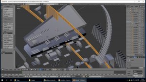
Here is the problem I forgot to address in the last post..and why it is taking LONG TIME NO JOY...
Progress-Beta35.jpg
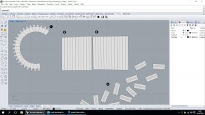
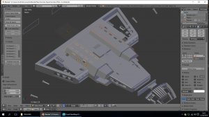
if you look at the highlighted section, you see that it passes through many pieces of other meshes...( Not Good !) and if you look at the inner an outer edges..they are actually made up of several fillets...as you zoom in closer and closer..it starts to look like the old weather brass weather stripping for double-hung windows...and each chunk has a face to be unfolded... computer was struggling just to zoom in close enough to view the things much less manipulate and deal with them!! Every thing in this!! EVERY @@%$## THING is like this! so hours and days spent just deciding what to move/layer/change cut/delete ad nauseum!! It was so bad on certain parts..boolean functions DIED!! I took days researching functions..retro-fitting and re-writing python scripts...and finally got to a functioning point that is CLOSE ENOUGH!!

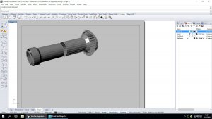
With more time I know I can get good results with Rhino..It is a GREAT PROGRAM! but with my lack of experience..only worked with it for a few weeks/ hours really..and was getting results like

Wanted to flatten small section of cannon... Rhino had trouble with the whole mesh...
DetailPage.jpg

with Rhino..got this result....
DetailPage2.jpg

My way..I got the whole cannon like this....without any moving stuff around...

g258.png
so...I DID IT MY WAY!:) on to the 50,000 other meshes waiting!!:(
 

Gandolf50

Researcher of obscure between war vehicles...
Staff member
Moderator
Jan 28, 2013
1,327
1,576
96
New Mexico USA
Gandolf,

Am ready to go. Working on the turret plates tonight. I believe that there might be additional modifications to it. If so I'll share with everyone. Trying to get an idea where your bottom pics will go. Feeling like this is becoming a 3d puzzle. It'll be F-U-N.

Sky Seeker
:tank:
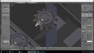
That bottom pic was the tiny little coke bottle cap looking things ( 6 in all ) on the top and bottom... called them Engine details.for lack of a better term...
Engine-detail.jpg
 

Sky Seeker

Well Established Member
Jun 1, 2015
1,178
1,083
95
Here is the problem I forgot to address in the last post..and why it is taking LONG TIME NO JOY...
View attachment 156051
if you look at the highlighted section, you see that it passes through many pieces of other meshes...( Not Good !) and if you look at the inner an outer edges..they are actually made up of several fillets...as you zoom in closer and closer..it starts to look like the old weather brass weather stripping for double-hung windows...and each chunk has a face to be unfolded... computer was struggling just to zoom in close enough to view the things much less manipulate and deal with them!! Every thing in this!! EVERY @@%$## THING is like this! so hours and days spent just deciding what to move/layer/change cut/delete ad nauseum!! It was so bad on certain parts..boolean functions DIED!! I took days researching functions..retro-fitting and re-writing python scripts...and finally got to a functioning point that is CLOSE ENOUGH!!

With more time I know I can get good results with Rhino..It is a GREAT PROGRAM! but with my lack of experience..only worked with it for a few weeks/ hours really..and was getting results like

Wanted to flatten small section of cannon... Rhino had trouble with the whole mesh...
View attachment 156052

with Rhino..got this result....
View attachment 156053

My way..I got the whole cannon like this....without any moving stuff around...
View attachment 156054
so...I DID IT MY WAY!:) on to the 50,000 other meshes waiting!!:(

Gandolf,

For picture number 1 - Yes there are a lot of details there. If we're going for a large phase 3 model with all the bells and whistles that might be a concern. For a phase 2 model (not as much detail) we could probably scrap most of the small details (build wise) and just make them graphics on some of the larger pieces for greebling later on.

For the cannon detail (pictures 2 and 3) I might have to scale it down just a tad to make it comparable to what I have right now. Looks good though!:)

Sky Seeker
:tank:
 
  • Like
Reactions: zathros

Sky Seeker

Well Established Member
Jun 1, 2015
1,178
1,083
95
That bottom pic was the tiny little coke bottle cap looking things ( 6 in all ) on the top and bottom... called them Engine details.for lack of a better term...
View attachment 156055

Gandolf,

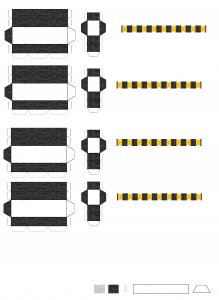
I was just looking at the lightwave model. The coke bottle cap things I think could probably be done on a graphic with layered greebling for extra added depth later on. On my model they would be too tiny to cut. Still trying to find an example of this from the ships in the show. BTW I've designed the golden ribs / ridges that are on top of the engine nacelles. Have figured out a way to do the ribs / ridges in one piece instead of cutting 36 individual pieces. Will post the pics once I'm done cutting, gluing, and assembling. Here's the template I have now for the nacelles on top and below the main body. The dark grey detail needs to be lighted up a bit.

upload_2016-12-27_19-36-35.jpeg

Sky Seeker
:tank:
 

Gandolf50

Researcher of obscure between war vehicles...
Staff member
Moderator
Jan 28, 2013
1,327
1,576
96
New Mexico USA
My
Gandolf,

I was just looking at the lightwave model. The coke bottle cap things I think could probably be done on a graphic with layered greebling for extra added depth later on. On my model they would be too tiny to cut. Still trying to find an example of this from the ships in the show. BTW I've designed the golden ribs / ridges that are on top of the engine nacelles. Have figured out a way to do the ribs / ridges in one piece instead of cutting 36 individual pieces. Will post the pics once I'm done cutting, gluing, and assembling. Here's the template I have now for the nacelles on top and below the main body. The dark grey detail needs to be lighted up a bit.

View attachment 156056

Sky Seeker
:tank:

My model is like 4 meters long man!! and I am not to the end yet!!;)
 

Gandolf50

Researcher of obscure between war vehicles...
Staff member
Moderator
Jan 28, 2013
1,327
1,576
96
New Mexico USA
Gandolf,

I was just looking at the lightwave model. The coke bottle cap things I think could probably be done on a graphic with layered greebling for extra added depth later on. On my model they would be too tiny to cut. Still trying to find an example of this from the ships in the show. BTW I've designed the golden ribs / ridges that are on top of the engine nacelles. Have figured out a way to do the ribs / ridges in one piece instead of cutting 36 individual pieces. Will post the pics once I'm done cutting, gluing, and assembling. Here's the template I have now for the nacelles on top and below the main body. The dark grey detail needs to be lighted up a bit.

View attachment 156056

Sky Seeker
:tank:

Yep.....either Greeble or printed..either way..have to be drawn!!
;)
 
  • Like
Reactions: zathros

zathros

*****SENIOR ADMINISTRATOR*****
Staff member
Administrator
Moderator
Apr 5, 2013
13,498
9,549
228
If that model were exported into Rhino, you would have to remove so many of the superfluous lines, that it would drive you nuts. I had one model that had 10 lines, going from the same point to the other point. Why someone would have to do that confounds me. I am working on the SSTO Shuttle from the movie "AVATAR" and the Mesh I have is such a mess, it really is just a reference.

If you imported the section of the model that has the highlighted sections, you could actually use that section as a "Cutting Tool" if you made it an "Polysurface". This looks like sloppy CAD work, to be honest. Whatever it took to get the outside shape. I would grab those curves that make up the outside shape, and put them in another layer. Delete what you don't need. Working with layers is the best way to isolate pieces, and take the strain off the computer generation the model.

Great work, but pain staking. Rhino works great for taking apart meshes and making something "real" out of them, but it is hard work, and takes a lot, a real lot, of time. This is true of all CAD programs. You get a truer model of the object in the end though, as opposed to Pepakura, which is a drawing program, not a CAD program. It is amazing what people make in Pepakura, but they always look like Pepakura models. You can't loft a hull in Pepakura and get true life results, that being said, I am amazed what the people who have mastered Pepakura make, and how fast they can bang it out, same goes with "Paint". I don't find these programs fulfilling though. It make because I make real things, then go to my milling machine, lathe, using compound rotary tables and reproduce them. I have to have all of those angle measurements, Sine, Cosine, and the X.Y,Z, coordinates.

You are doing a kick ass job though, and I imagine this will be the most accurate model of this ship available.

I would suggest you familiarize yourself with the "Transform" section and use the "Array along Curve" to make the repetitive parts. The "Transform" and "Curves" section are two of the most important sections. They allow you to turn the MESH into something Rhino can work with, and give you the opportunity to delete the superfluous crap, and will show you where it is.
 

Gandolf50

Researcher of obscure between war vehicles...
Staff member
Moderator
Jan 28, 2013
1,327
1,576
96
New Mexico USA
Gandolf,

For picture number 1 - Yes there are a lot of details there. If we're going for a large phase 3 model with all the bells and whistles that might be a concern. For a phase 2 model (not as much detail) we could probably scrap most of the small details (build wise) and just make them graphics on some of the larger pieces for greebling later on.

For the cannon detail (pictures 2 and 3) I might have to scale it down just a tad to make it comparable to what I have right now. Looks good though!:)

Sky Seeker
:tank:
Yeh...on the small scale..your talking..a basic tube and not much els,, as that is really all there is even in a fancy version!
 

zathros

*****SENIOR ADMINISTRATOR*****
Staff member
Administrator
Moderator
Apr 5, 2013
13,498
9,549
228
That nose of that ship- has to be water formed, or made out of forms and stringers, filled with either Bondo, or some other material and shaped into form. There is no other way to unfold something like that. The part should be cut in half (lengthwise) as it is better to work with halves. and if you want to work with paper, then use the Isocurves to form longitudinal strips to form the overall shape. This will lead to a part with many lines, but that is the best you can do for a paper model. Now if you make that parts somewhat smaller, then you could "Bondo" the surface and sand it to the desired shape. The limitation is trying to use only paper, not any of the programs, though these models were designed to make CGI models, not actual physical models. They should be treated as the reference that they are. ":)
 
  • Like
Reactions: Sky Seeker

Sky Seeker

Well Established Member
Jun 1, 2015
1,178
1,083
95
That nose of that ship- has to be water formed, or made out of forms and stringers, filled with either Bondo, or some other material and shaped into form. There is no other way to unfold something like that. The part should be cut in half (lengthwise) as it is better to work with halves. and if you want to work with paper, then use the Isocurves to form longitudinal strips to form the overall shape. This will lead to a part with many lines, but that is the best you can do for a paper model. Now if you make that parts somewhat smaller, then you could "Bondo" the surface and sand it to the desired shape. The limitation is trying to use only paper, not any of the programs, though these models were designed to make CGI models, not actual physical models. They should be treated as the reference that they are. ":)

Z - I'm thinking about maybe hand drawing some of the lines scanning and scaling appropriately to what has been done so far. That is after trying the Beta Build of what we got so far.

Sky Seeker
:tank:
 
  • Like
Reactions: zathros

Sky Seeker

Well Established Member
Jun 1, 2015
1,178
1,083
95
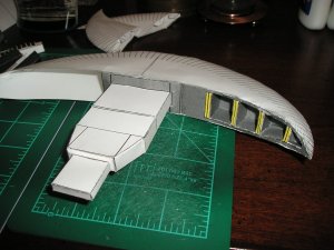
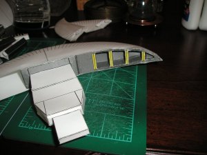
Here are some shots of what has been done so far.

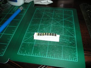
This is a prototype of the ribs. I put it on top of one of the nacelles created earlier. Note that it is too short and the ribs are too small. Will increase the size of the ribs as well as the distance of the in between portions.
upload_2016-12-28_13-44-39.jpeg

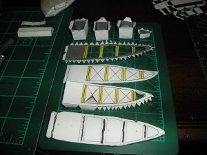
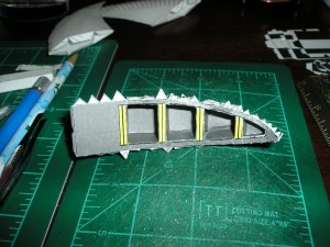
Here is the wing turret plate with the boxes assembled. The bottom most figure was the initial template formed from tracing the space between the wings of the ship. Once made, the template was scanned to create the primary wing plate up above. Note that it is too short. I found that when printing out the wing plate the paint program had shortened the figure for some reason (don't know why). In paint the plate was extended to get the next version (3rd from bottom). After that some coloring was added. The red "X" is to indicate that you can either cut out that space entirely OR you can cut along the red "X" to form tabs to hold the boxes in place.
upload_2016-12-28_13-46-32.jpeg

Boxes assembled to the wing plate.
upload_2016-12-28_13-52-28.jpeg

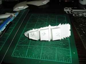
Back view. As you can see tabs attached to the boxes were used to hold everything together to the back of the plate.
upload_2016-12-28_13-52-49.jpeg

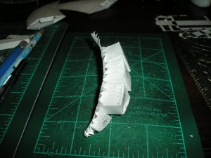
Side view. Note that the plate automatically curves.
upload_2016-12-28_13-53-55.jpeg

Plate assembled to the ship.
During assembly the right most edge (pointy portion) was glued in first then worked toward the main body. I was concerned I had made the small box too big for the space. Thankfully I was wrong. However, the second box (labeled 3A in the above pics) from the right extended too far back and caused a stress concentration which resulted in the bulging you see here. To get it to fit inside of the wing the back corner of the box was slightly dented in. Will have to make the box slightly thinner. Also, modified the templates for the 2nd and 3rd boxes. Will send out a new template when done with the redesigns.
upload_2016-12-28_13-54-10.jpeg

upload_2016-12-28_13-54-41.jpeg

After studying the lightwave model and the pictures from the show I'm going to be modifying this version to be as close to the show as I can make it. It's funny as you study something from the show and some of the fan made models I can immediately now see the differences. Some of the fan made models are overly complex in some areas and some are over-simplified.

This model for sure is an interesting learning experience with complex curves and simple curves that won't cooperate.

The joys of building!

Sky Seeker
:tank:
 
  • Like
Reactions: zathros

Gandolf50

Researcher of obscure between war vehicles...
Staff member
Moderator
Jan 28, 2013
1,327
1,576
96
New Mexico USA
If that model were exported into Rhino, you would have to remove so many of the superfluous lines, that it would drive you nuts. I had one model that had 10 lines, going from the same point to the other point. Why someone would have to do that confounds me. I am working on the SSTO Shuttle from the movie "AVATAR" and the Mesh I have is such a mess, it really is just a reference.

If you imported the section of the model that has the highlighted sections, you could actually use that section as a "Cutting Tool" if you made it an "Polysurface". This looks like sloppy CAD work, to be honest. Whatever it took to get the outside shape. I would grab those curves that make up the outside shape, and put them in another layer. Delete what you don't need. Working with layers is the best way to isolate pieces, and take the strain off the computer generation the model.

Great work, but painstaking. Rhino works great for taking apart meshes and making something "real" out of them, but it is hard work, and takes a lot, a real lot, of time. This is true of all CAD programs. You get a truer model of the object in the end though, as opposed to Pepakura, which is a drawing program, not a CAD program. It is amazing what people make in Pepakura, but they always look like Pepakura models. You can't loft a hull in Pepakura and get true life results, that being said, I am amazed what the people who have mastered Pepakura make, and how fast they can bang it out, same goes with "Paint". I don't find these programs fulfilling though. It make because I make real things, then go to my milling machine, lathe, using compound rotary tables and reproduce them. I have to have all of those angle measurements, Sine, Cosine, and the X.Y,Z, coordinates.

You are doing a kick ass job though, and I imagine this will be the most accurate model of this ship available.

I would suggest you familiarize yourself with the "Transform" section and use the "Array along Curve" to make the repetitive parts. The "Transform" and "Curves" section are two of the most important sections. They allow you to turn the MESH into something Rhino can work with, and give you the opportunity to delete the superfluous crap, and will show you where it is.

I just about wore out the transform function/ along with snap to ....... wanted to use the chain function but it would only run 1- a few meshes and quit..so ended up point and click anyway which was a shame..just the way the mesh was..

I really think that part of the problem was importing from a lightwave file...which was a nurb to begin with..just not a Rhino Nurb...so everything was just a bit wonky! You know how you get the option when extracting mesh from nurb and your slider for more or less ..I got neither..it just changed where they were located...really made no difference if I picked the least of the most...

and when flattening..no matter which I used squish smash unrollsrf unrollsrfuv they all came out virtually identical...

I made some tutorials to learn some of the functions and see how things were supposed to work..they will never work with this mesh as it is! Unless I took and recreated the vorchan using rhino and then..things would work...

Talk about LINES! I have to pick all the vertices of an object out of this thing just to isolate it to flatten it......IT IS a NIGHTMARE!! Remember awhile back talking how to do a hole in Rhino..?
Well all the highlighted cutouts on this image start from a point towards the front of the thing! Now I know why my boolean operations cried for mercy!
Body-Engine-Pods.jpg what is sad..I still have to go back and hand cut this thing to fit with the other as it is 4 separate objects merged together...
Luckily..all the doodads and eye-candy... I can just pick one and flatten and copy however how many are needed!
 

spaceagent-9

Right Hand Man and Confidant
Moderator
Jul 10, 2013
3,114
3,479
143
62
pheonix
pray for rainy days.......

well keep up the good work! its still a great project and im watching you work this out with fascination!
 

Sky Seeker

Well Established Member
Jun 1, 2015
1,178
1,083
95
I just about wore out the transform function/ along with snap to ....... wanted to use the chain function but it would only run 1- a few meshes and quit..so ended up point and click anyway which was a shame..just the way the mesh was..

I really think that part of the problem was importing from a lightwave file...which was a nurb to begin with..just not a Rhino Nurb...so everything was just a bit wonky! You know how you get the option when extracting mesh from nurb and your slider for more or less ..I got neither..it just changed where they were located...really made no difference if I picked the least of the most...

and when flattening..no matter which I used squish smash unrollsrf unrollsrfuv they all came out virtually identical...

I made some tutorials to learn some of the functions and see how things were supposed to work..they will never work with this mesh as it is! Unless I took and recreated the vorchan using rhino and then..things would work...

Talk about LINES! I have to pick all the vertices of an object out of this thing just to isolate it to flatten it......IT IS a NIGHTMARE!! Remember awhile back talking how to do a hole in Rhino..?
Well all the highlighted cutouts on this image start from a point towards the front of the thing! Now I know why my boolean operations cried for mercy!
View attachment 156102 what is sad..I still have to go back and hand cut this thing to fit with the other as it is 4 separate objects merged together...
Luckily..all the doodads and eye-candy... I can just pick one and flatten and copy however how many are needed!

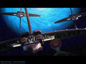
Now you know why I opted for the "clean build option". The lightwave model had a lot of parts that we don't need for a build. I was hoping that for the nose portion that you could maybe get something close to what is needed. Besides CGI does things that in the real world don't quite work - especially with paper. With paper we have to think differently like - "how am I to assemble this flat paper to a 3d object". Literal cutting and pasting is quite different from computer cut and paste. Sometimes when the virtual meets the real the end doesn't end too well. However, sometimes the one can give insight into the other. Like how you did the nose. How you broke it down and this image gave me an idea -

upload_2016-12-29_16-1-52.jpeg

Look at the nose of the lead Centauri. Now think of an "X" formed by the two sides leading to the middle or nose or beak. I think that this could be a good start point for a design. BTW this picture is as close to the "canon" ships as I've seen so far.

Note one of the artists Amras Arfeiniel, has made a lot of other B5 related works. See here for additional works:

http://amras-arfeiniel.deviantart.com/art/Darkness-Ascending-83790187

Enjoy!

Sky Seeker
:tank:
 
Last edited:
  • Like
Reactions: zathros

Gandolf50

Researcher of obscure between war vehicles...
Staff member
Moderator
Jan 28, 2013
1,327
1,576
96
New Mexico USA
Gandolf,

I was just looking at the lightwave model. The coke bottle cap things I think could probably be done on a graphic with layered greebling for extra added depth later on. On my model they would be too tiny to cut. Still trying to find an example of this from the ships in the show. BTW I've designed the golden ribs / ridges that are on top of the engine nacelles. Have figured out a way to do the ribs / ridges in one piece instead of cutting 36 individual pieces. Will post the pics once I'm done cutting, gluing, and assembling. Here's the template I have now for the nacelles on top and below the main body. The dark grey detail needs to be lighted up a bit.

View attachment 156056

Sky Seeker
:tank:

I hear / what you mean about puzzle..shame about screen grabs from the show being so ( bad ) ...I have no idea where your gold ribs are at..I have nothing in / like that on any import from the lightwave file....
 
  • Like
Reactions: Sky Seeker

Sky Seeker

Well Established Member
Jun 1, 2015
1,178
1,083
95
I hear / what you mean about puzzle..shame about screen grabs from the show being so ( bad ) ...I have no idea where your gold ribs are at..I have nothing in / like that on any import from the lightwave file....

Look at the pics from the show. Also look up various detailed pictures of the Vorchan on image sites. The gold ribs are located on top of the body "nacelles". You'll see what I'm talking about in the next couple of days after I assemble them to the main body. BTW that is "canon". The ribs are also located if you look at the picture above on either side of the main gun or cannon. The nacelles in the pic are purple while in the show they are grey.

Sky Seeker
:tank:
 

Gandolf50

Researcher of obscure between war vehicles...
Staff member
Moderator
Jan 28, 2013
1,327
1,576
96
New Mexico USA
Look at the pics from the show. Also look up various detailed pictures of the Vorchan on image sites. The gold ribs are located on top of the body "nacelles". You'll see what I'm talking about in the next couple of days after I assemble them to the main body. BTW that is "canon". The ribs are also located if you look at the picture above on either side of the main gun or cannon. The nacelles in the pic are purple while in the show they are grey.

Sky Seeker
:tank:
Oh...ok you are doing a different version...
 
  • Like
Reactions: Sky Seeker

zathros

*****SENIOR ADMINISTRATOR*****
Staff member
Administrator
Moderator
Apr 5, 2013
13,498
9,549
228
The only way to work with these meshes is to go to "Curves/Extract WireFrame. Then move the highlighted Wireframe (which is superimposed on the original Mesh) over and you will have the Mesh in the format that Rhino uses. If you click, you will take the highlighting away and lose the new Mesh, in that case, go backwards, and repeat the process. You can "Group" the Highlighted Mesh, to keep it together. You will see the original Mesh when you move the New Rhino Mesh over. That's when you start picking out and deleting the superfluous crap. Any other method is arduous and a waste of time. IMHO. :)
 
  • Like
Reactions: Sky Seeker

Sky Seeker

Well Established Member
Jun 1, 2015
1,178
1,083
95
Oh...ok you are doing a different version...

Yes. For some of the surface features. The "bones" as you called it earlier - that basic foundation of the ship (nose, fuselage, wings, vertical stabilizers etc.) should be "roughly" the same. After that there will be some deviation (ok mutation) going on!;) Although I'll be happy to beta test the lightwave version that you're planning.

Sky Seeker
:tank:
 
Last edited:
  • Like
Reactions: zathros