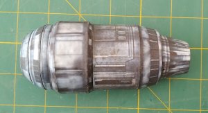
Razor Crest from Mandalorian / Roland Tari
- Thread starter bigpetr
- Start date
You are using an out of date browser. It may not display this or other websites correctly.
You should upgrade or use an alternative browser.
You should upgrade or use an alternative browser.
BEFORE GLUING PARTS TOGETHER, CHECK THAT THE TABS DO NOT INTERFERE WITH EACH OTHER – TRIM IF NECESSARY.
There are modifications to the tabs on R & R1 (Page 03.pdf) and L4 is no longer required (Page 08.pdf). The modified pages have been uploaded.
I assembled the parts of the cockpit as per the original shapes but was not happy with the way the canopy was joined and the method of the curve.
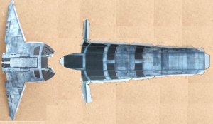
I decided to combine the 4 separate parts into one piece and make alternative parts for the front curved side windows.
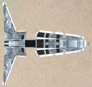
Assemble part L3.
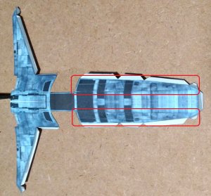
Now curve the parts as shown.

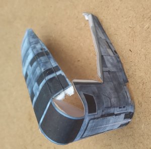
Start by Attaching L3c to the right side of the cockpit and L3d to the left side as shown.

Now glue the next tab, moulding the canopy with your fingers.
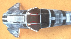
When completely dry, glue the next tab.
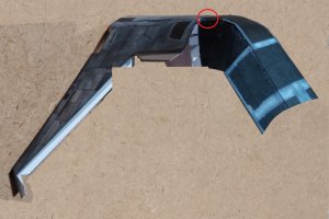
And finally, glue the rest of the tabs.
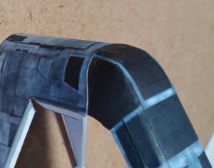

There are modifications to the tabs on R & R1 (Page 03.pdf) and L4 is no longer required (Page 08.pdf). The modified pages have been uploaded.
I assembled the parts of the cockpit as per the original shapes but was not happy with the way the canopy was joined and the method of the curve.

I decided to combine the 4 separate parts into one piece and make alternative parts for the front curved side windows.

Assemble part L3.

Now curve the parts as shown.


Start by Attaching L3c to the right side of the cockpit and L3d to the left side as shown.

Now glue the next tab, moulding the canopy with your fingers.

When completely dry, glue the next tab.

And finally, glue the rest of the tabs.


Last edited:
Assemble parts L, L1 & L2.
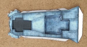
Start attaching part L to the cockpit by aligning the centre.
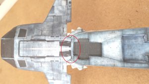
Gradually glue the tabs working from the centre.
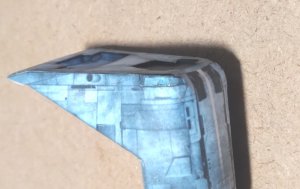
I found that it was not very rigid where the cockpit attaches to the top of the body so I cut out a section and glued in a 1mm piece of card underneath the cut-out to flatten out the mounting position.
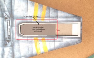
Start by attaching the cockpit to the body at the tab shown.
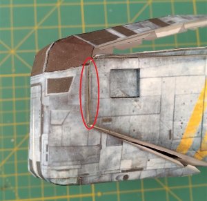
When dry, glue the corresponding tab on the right side of the cockpit. Gluing the rest of the cockpit is a bit tricky and I found that the best way was to use thick superglue for a quick bond.
Fit L4a & L4b and the front lamps. Any imperfections on the side joins of the cockpit will be covered by front shields L4a & L4b.
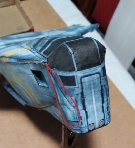
Join R to R1.
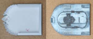
Now glue the roof to the top of the body to the rear of the cockpit.
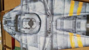
Now for the engines.........

Start attaching part L to the cockpit by aligning the centre.

Gradually glue the tabs working from the centre.

I found that it was not very rigid where the cockpit attaches to the top of the body so I cut out a section and glued in a 1mm piece of card underneath the cut-out to flatten out the mounting position.

Start by attaching the cockpit to the body at the tab shown.

When dry, glue the corresponding tab on the right side of the cockpit. Gluing the rest of the cockpit is a bit tricky and I found that the best way was to use thick superglue for a quick bond.
Fit L4a & L4b and the front lamps. Any imperfections on the side joins of the cockpit will be covered by front shields L4a & L4b.

Join R to R1.

Now glue the roof to the top of the body to the rear of the cockpit.

Now for the engines.........
Last edited:
I thought the engines would be easy.........
I came to the conclusion that round formers were required to provide rigidity. The tabs on most of the parts had to be repositioned to make assembly easier and neater. I have struggled with the nose cone strips not meeting up properly but after numerous different versions, I think that I have got the measurements and sequence correct. I will try the latest version of parts this weekend.
I came to the conclusion that round formers were required to provide rigidity. The tabs on most of the parts had to be repositioned to make assembly easier and neater. I have struggled with the nose cone strips not meeting up properly but after numerous different versions, I think that I have got the measurements and sequence correct. I will try the latest version of parts this weekend.
ENGINES...
I decided to make 1mm card formers as there was no rigidity in the engine units. This would also make it easier to keep their shapes when gluing the various stages. Also, there was no inner cladding to cover the insides of the engine intakes and exhausts so I added these also.
The only difference that I found between the two engines was that one of them had a small piece out of the front cowl. For simplicity, I decided to make both engines the same. Therefore they can be constructed together as the parts are identical for each engine.
I was not happy with the original single piece front assembly part (E2) as I felt that with the three bands joined, this complicated the gluing of the bands to each other causing a “bump” where there were no tabs. I also found that sometimes the parts did not line up properly.
I therefore decided to split this part into 3 separate bands which made assembly easier and the parts fitted perfectly every time.
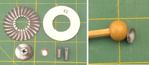
I “domed” part E1a with a tool made from a skewer and wooden ball from a craft shop.
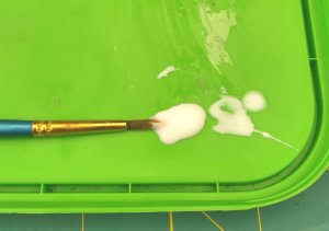
For applying pva with a toothpick or paintbrush, I use an old margarine lid on which I put a dab of pva. Any residue left over will peel off after drying.
Assemble E1b with joiner J1 and assemble parts E1d.
Glue E1a to E1b (matching the colour pattern) and then attach E1b to E1c.
When dry, glue this sub-assembly to former E1 and then attach 2 x parts E1d.

Assemble E2a with joiner J2, E2b with joiner J3 and E2c with joiner J4.
Glue assembly E1 inside E2a midway between the front and the rear (the rear has square tabs).
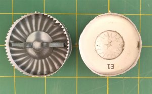
Bend the triangular tabs of E2a inwards at 45°. Coat the inner edge of E2b with pva and slide it over the tabs of E2a and gently work it so that it fits neatly all around E2a without any tabs showing. Now gently crimp the tabs with flat nosed tweezers.
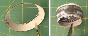
Now glue the inner liner strip E2d in place as shown.
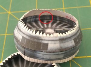
Now repeat this process with E2c.

Coil up the inner liner E2e and insert it into the cowl. Glue the top corner in place as shown. When dry, run a bead of glue along the inside of the top edge of E2c and fit the rest of the liner in place.
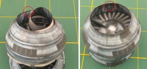
Join rings E3a with joiner J5, E3b with joiner J6 and E4a with joiner J7.
Attach E3a to ring E3b.
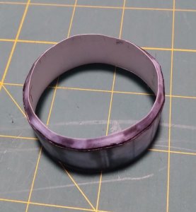
Flatten out the square tabs on E2a and then carefully run a bead of pva along these tabs as shown.
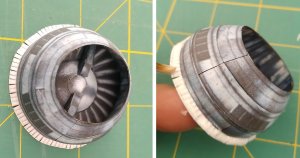
Now slide ring E3b over the cowl assembly and fit onto the square tabs in the same manner as the cowl rings were assembled.
Make sure that the parts E1d on the front of the intake fan are in line with the red dot on ring E3b which will be the bottom of the engine.
Crimp as before then run a band of pva along the inside of the square tabs to seal them.
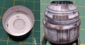
Test fit former E3c, sanding a chamfer around the edge so that it is a sliding fit in ring E3b.
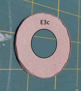
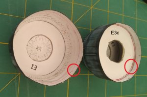
Draw a line about 5mm inside E3b, run a bead of glue along it and push former E3c into place.
I decided to make 1mm card formers as there was no rigidity in the engine units. This would also make it easier to keep their shapes when gluing the various stages. Also, there was no inner cladding to cover the insides of the engine intakes and exhausts so I added these also.
The only difference that I found between the two engines was that one of them had a small piece out of the front cowl. For simplicity, I decided to make both engines the same. Therefore they can be constructed together as the parts are identical for each engine.
I was not happy with the original single piece front assembly part (E2) as I felt that with the three bands joined, this complicated the gluing of the bands to each other causing a “bump” where there were no tabs. I also found that sometimes the parts did not line up properly.
I therefore decided to split this part into 3 separate bands which made assembly easier and the parts fitted perfectly every time.
I “domed” part E1a with a tool made from a skewer and wooden ball from a craft shop.

For applying pva with a toothpick or paintbrush, I use an old margarine lid on which I put a dab of pva. Any residue left over will peel off after drying.

Assemble E1b with joiner J1 and assemble parts E1d.
Glue E1a to E1b (matching the colour pattern) and then attach E1b to E1c.
When dry, glue this sub-assembly to former E1 and then attach 2 x parts E1d.

Assemble E2a with joiner J2, E2b with joiner J3 and E2c with joiner J4.
Glue assembly E1 inside E2a midway between the front and the rear (the rear has square tabs).

Bend the triangular tabs of E2a inwards at 45°. Coat the inner edge of E2b with pva and slide it over the tabs of E2a and gently work it so that it fits neatly all around E2a without any tabs showing. Now gently crimp the tabs with flat nosed tweezers.

Now glue the inner liner strip E2d in place as shown.

Now repeat this process with E2c.

Coil up the inner liner E2e and insert it into the cowl. Glue the top corner in place as shown. When dry, run a bead of glue along the inside of the top edge of E2c and fit the rest of the liner in place.

Join rings E3a with joiner J5, E3b with joiner J6 and E4a with joiner J7.
Attach E3a to ring E3b.

Flatten out the square tabs on E2a and then carefully run a bead of pva along these tabs as shown.

Now slide ring E3b over the cowl assembly and fit onto the square tabs in the same manner as the cowl rings were assembled.
Make sure that the parts E1d on the front of the intake fan are in line with the red dot on ring E3b which will be the bottom of the engine.
Crimp as before then run a band of pva along the inside of the square tabs to seal them.

Test fit former E3c, sanding a chamfer around the edge so that it is a sliding fit in ring E3b.

Draw a line about 5mm inside E3b, run a bead of glue along it and push former E3c into place.

Last edited:
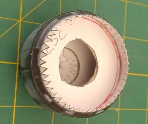
Glue two tabs of ring E4a in place on E3b.
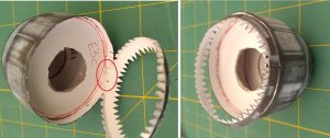
When dry, glue the rest of ring E4a in place.
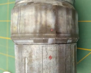
Assemble ring E4b with joiner J8.
Run a bead of glue along the inside of the front edge of E4b and fit it over the tabs of E4a, note that the red dot on E4b lines up with the red dot on E3b.
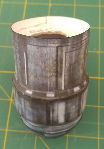
Chamfer the edge of former E4c so that it fits into E4b. As with E3b, draw a line about 5mm inside E4b, run a bead of glue along it and push former E4c into place.
Assemble conical ring E4d with joiner J9. Join ring E4d to ring E4b.
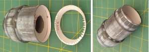
Carefully chamfer the edges of former E4e so that it is a perfect flush fit in the end of conical ring E4d. (Slide it in vertically and pull it back up using bent tweezers). Make sure that its face is smooth.
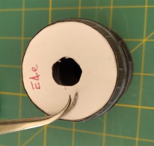
Remove it and coat the inside edge of conical ring E4d with pva and then refit E4e, pulling it back up so that it is flush with the top all around.
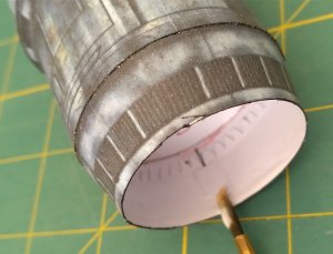
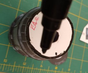
When dry, colour the outer edge of the former black. (I used a permanent marker with a thin tip).
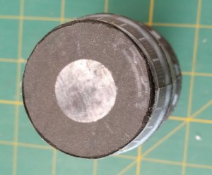
Trim disc E4f to fit and glue it on.

When dry, glue the rest of ring E4a in place.

Assemble ring E4b with joiner J8.
Run a bead of glue along the inside of the front edge of E4b and fit it over the tabs of E4a, note that the red dot on E4b lines up with the red dot on E3b.

Chamfer the edge of former E4c so that it fits into E4b. As with E3b, draw a line about 5mm inside E4b, run a bead of glue along it and push former E4c into place.

Assemble conical ring E4d with joiner J9. Join ring E4d to ring E4b.

Carefully chamfer the edges of former E4e so that it is a perfect flush fit in the end of conical ring E4d. (Slide it in vertically and pull it back up using bent tweezers). Make sure that its face is smooth.

Remove it and coat the inside edge of conical ring E4d with pva and then refit E4e, pulling it back up so that it is flush with the top all around.

When dry, colour the outer edge of the former black. (I used a permanent marker with a thin tip).

Trim disc E4f to fit and glue it on.

Assemble cone E5c with joiner J9 and then glue in the inner liner E5d (it may need trimming).
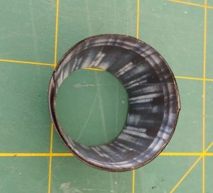
Chamfer former E5a to fit flush at the back of E5c. Make sure both sides are smooth. Glue disc E5b to the front of the former and when dry, trim it to the former from the rear and colour the edge black.
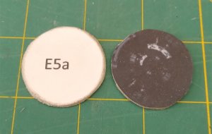
Now glue it in place at the rear of cone E5c and when dry, glue it in the centre of disc E4f.
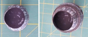
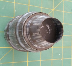
Construct part E6 and then glue it to the engine.

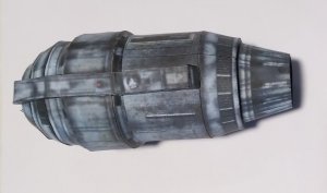
I have decided to not mount the engines yet as I think that the upper body need another profiled cross member made from 1mm card placed across the body from engine to engine to maintain the body shape and also profiled card at each "wing" end where the engines mount.

Chamfer former E5a to fit flush at the back of E5c. Make sure both sides are smooth. Glue disc E5b to the front of the former and when dry, trim it to the former from the rear and colour the edge black.

Now glue it in place at the rear of cone E5c and when dry, glue it in the centre of disc E4f.


Construct part E6 and then glue it to the engine.


I have decided to not mount the engines yet as I think that the upper body need another profiled cross member made from 1mm card placed across the body from engine to engine to maintain the body shape and also profiled card at each "wing" end where the engines mount.
Last edited:
I've discovered a difference in the engines. What appears to be inspection hatches on the side determines that these hatches should be on the outside of each engine when mounted on the wing. I've therefore "handed" parts E4b and made them E4b port and E4b starboard. The amended pdf's have been uploaded to Mediafire.

 www.mediafire.com

MediaFire
MediaFire is a simple to use free service that lets you put all your photos, documents, music, and video in a single place so you can access them anywhere and share them everywhere.
Thank you very much for sharing this with us!I've discovered a difference in the engines. What appears to be inspection hatches on the side determines that these hatches should be on the outside of each engine when mounted on the wing. I've therefore "handed" parts E4b and made them E4b port and E4b starboard. The amended pdf's have been uploaded to Mediafire.

MediaFire
MediaFire is a simple to use free service that lets you put all your photos, documents, music, and video in a single place so you can access them anywhere and share them everywhere.www.mediafire.com


