

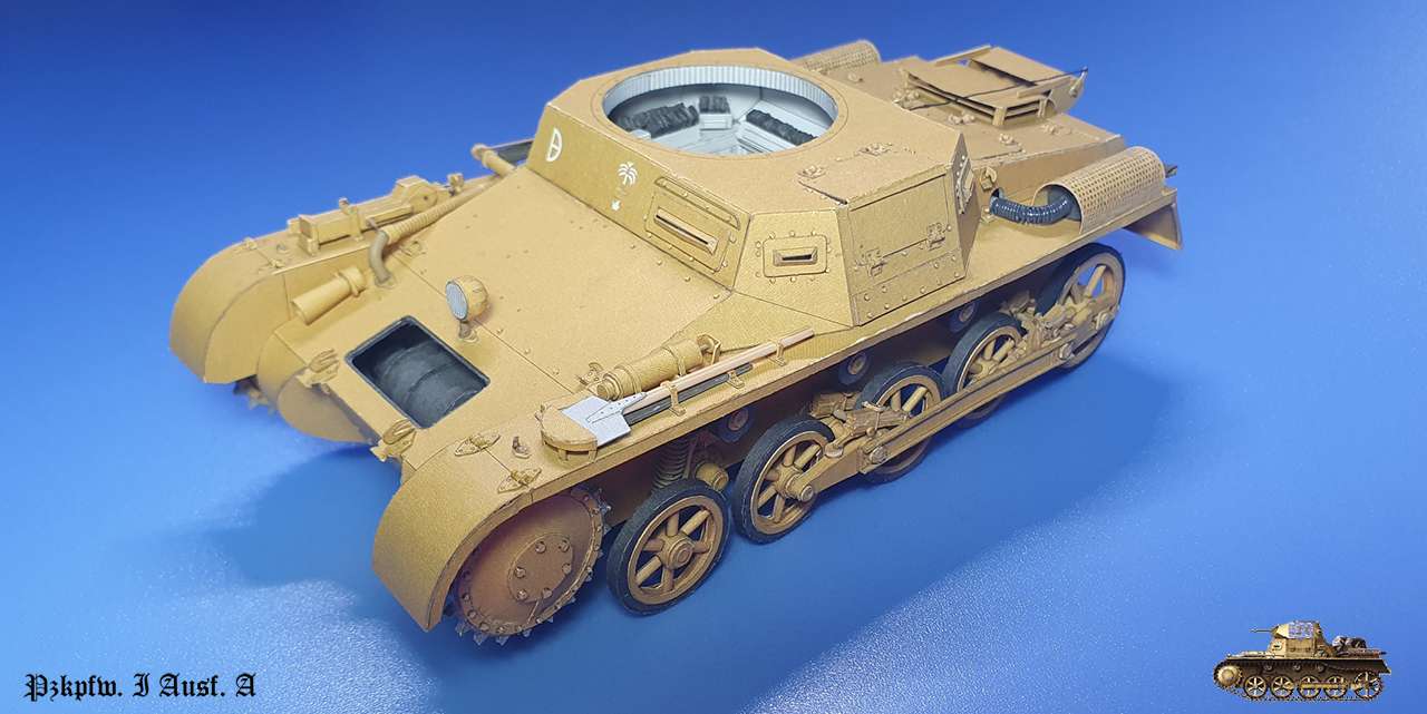
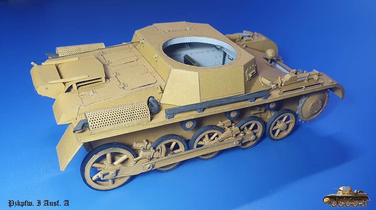
Pzkpfw. I Ausf. A, Orlik, 1:25
- Thread starter snake7
- Start date
You are using an out of date browser. It may not display this or other websites correctly.
You should upgrade or use an alternative browser.
You should upgrade or use an alternative browser.
Hi
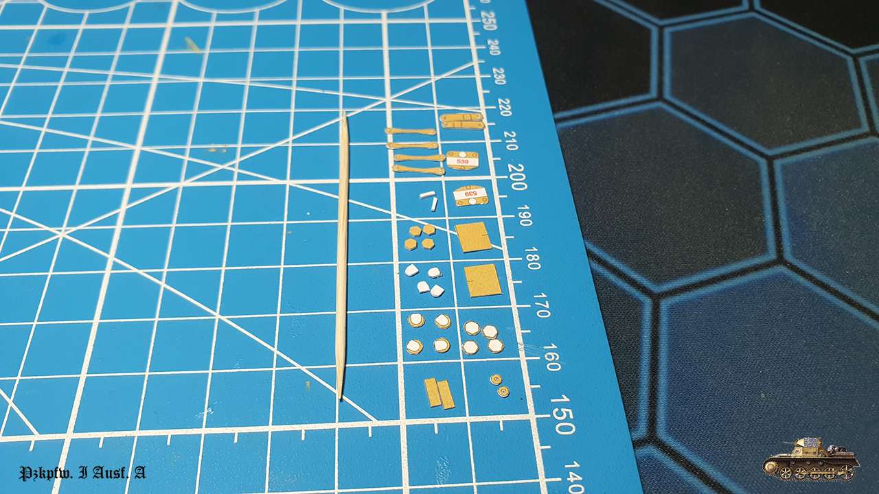
After summer vacation - back to the model.
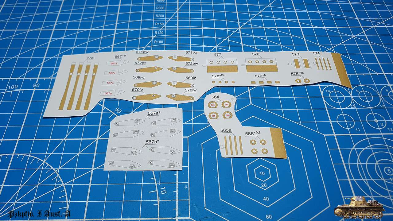
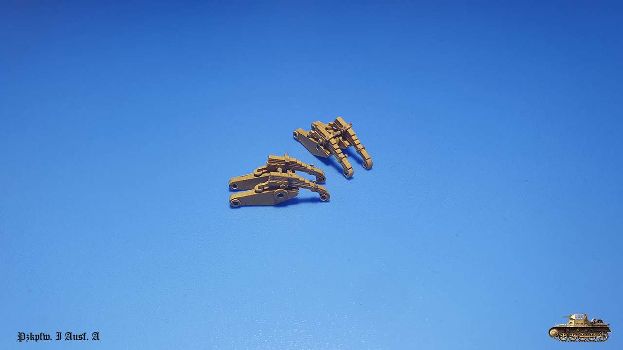
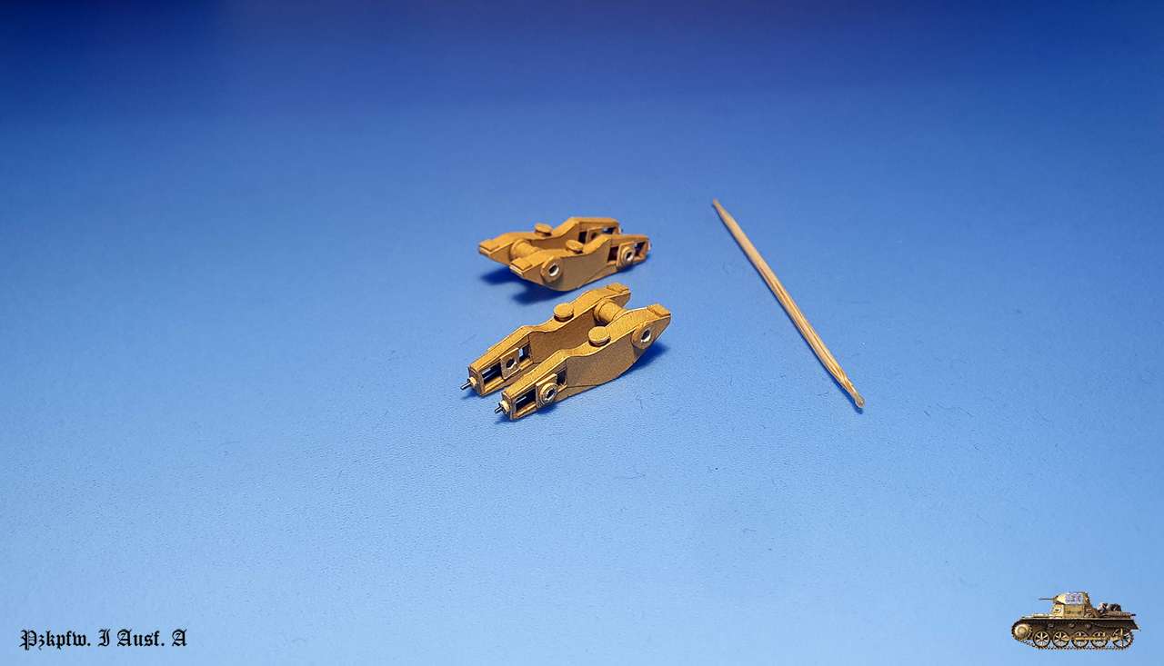
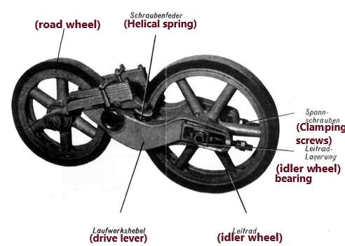
Continue with suspension. In this tank it is unique and complex... I wonder what the reason behind this engineering idea was.
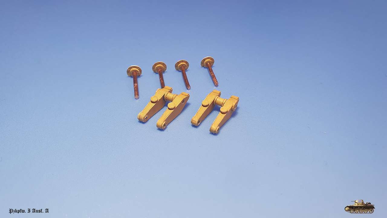
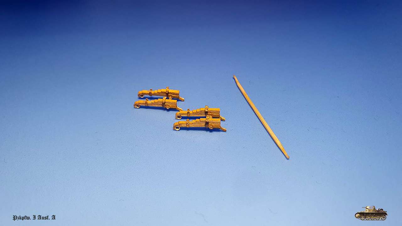
Nevertheless, front lever with amortization.

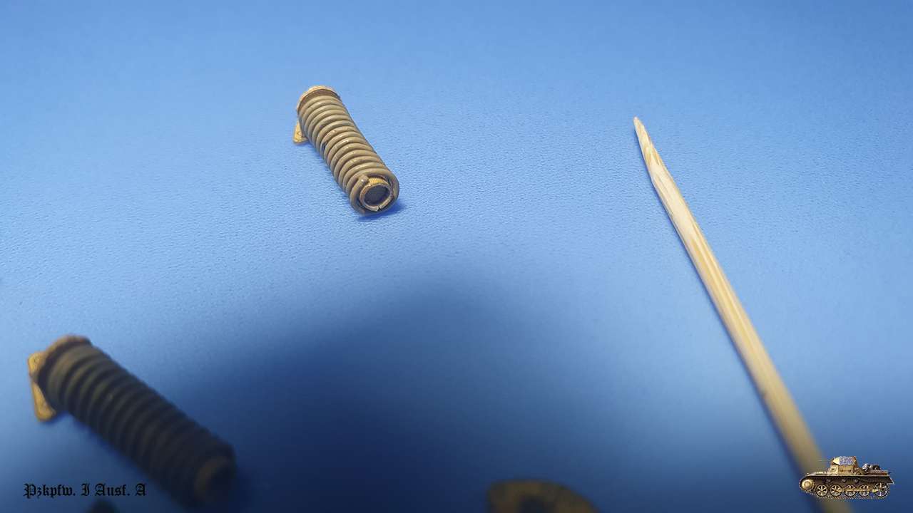
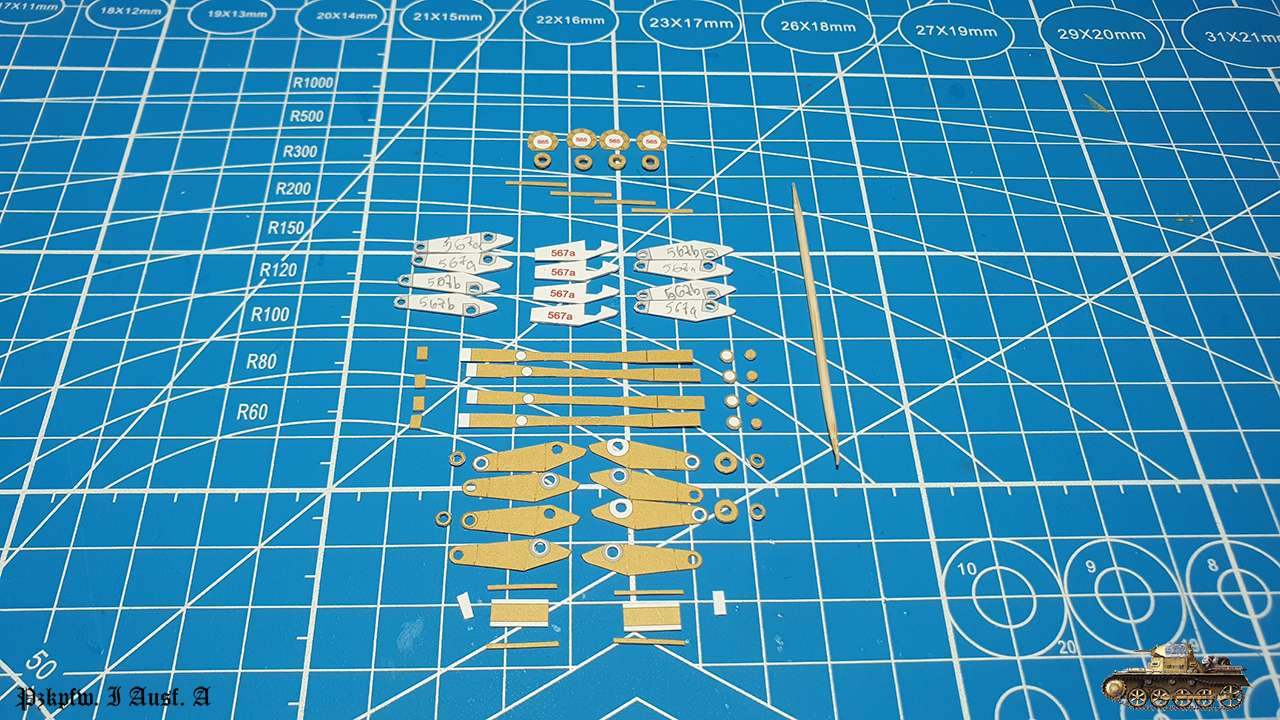
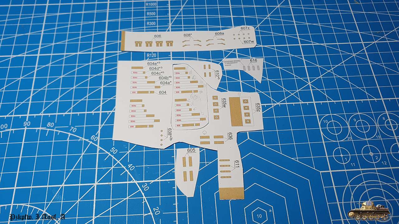
A lot of small parts.

Here is the comparison to toothpick
Whole assembling broken to stages and after i built all of them, I didn't connect together for easy installation and adjustment in the future.
In addition, everywhere when possible i glued parts with superglue gel, for strength.
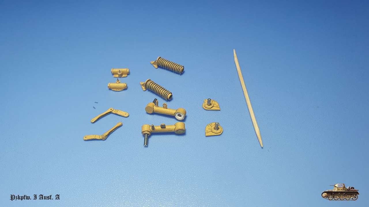
Pay attention to part 551. You need to glue inside circle 0.6 mm deep, so it could be positioned on a lever pin.
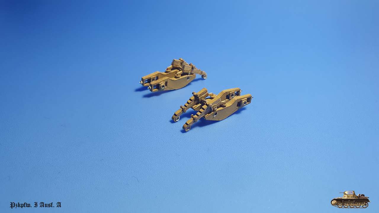
And this is dry fit for how it will be assembled together.
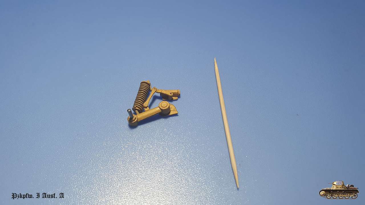
I will not attach this construction to hull yet, because I need an alignment relatively to other bogies and I don't want for now that all the weight will be put only on two wheels.
Errors:
Part 524 labeled 424 on diagrams.
I'm sure part 534 must be glued on 0.5 cardboard, but it isn't signed with asterisk.
After summer vacation - back to the model.
Continue with suspension. In this tank it is unique and complex... I wonder what the reason behind this engineering idea was.
Nevertheless, front lever with amortization.
A lot of small parts.
Here is the comparison to toothpick
Whole assembling broken to stages and after i built all of them, I didn't connect together for easy installation and adjustment in the future.
In addition, everywhere when possible i glued parts with superglue gel, for strength.
Pay attention to part 551. You need to glue inside circle 0.6 mm deep, so it could be positioned on a lever pin.
And this is dry fit for how it will be assembled together.
I will not attach this construction to hull yet, because I need an alignment relatively to other bogies and I don't want for now that all the weight will be put only on two wheels.
Errors:
Part 524 labeled 424 on diagrams.
I'm sure part 534 must be glued on 0.5 cardboard, but it isn't signed with asterisk.
Last edited:
Thanks guys!
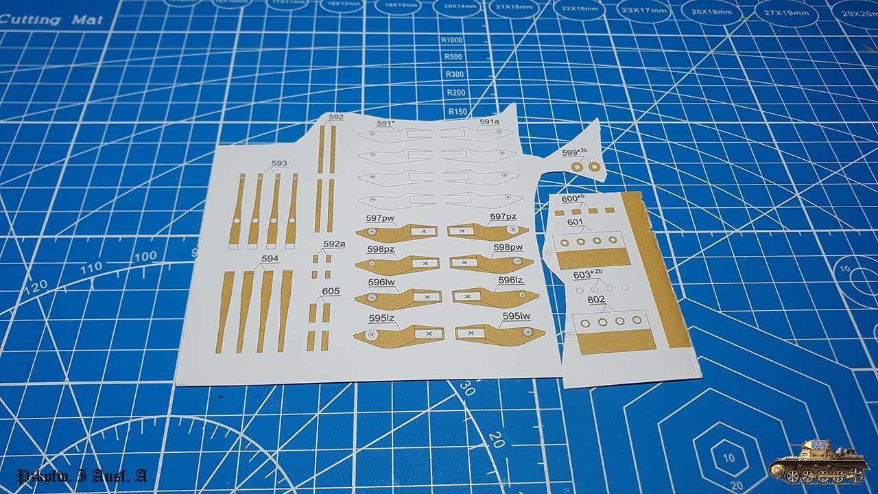
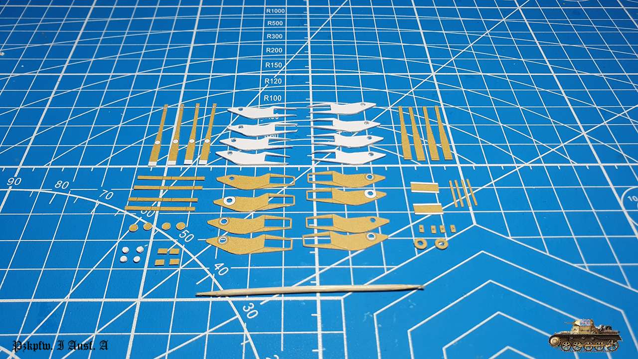
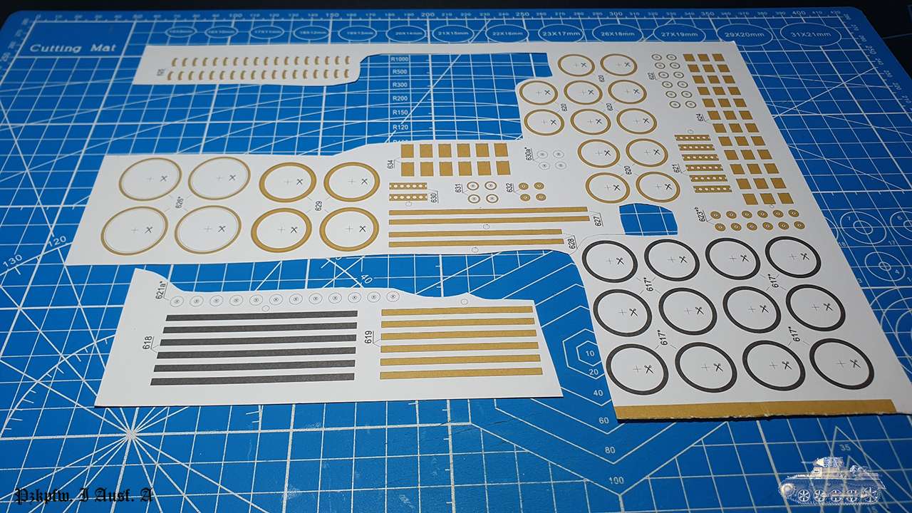
First two front wheels.
I struggled with those and still don't understand if it is my mistake or design flaw.
I cut inner ring diameter precisely, but inner strip was half mm big and afterwards wheels spokes didn't match in it. So, I was in need to adjust one by one.
By default, spokes are hit and miss, because you cannot assemble 100% perfect. But here it was a real issue.
Later will be more wheels and I'll do an experiment with first one to understand what's wrong.
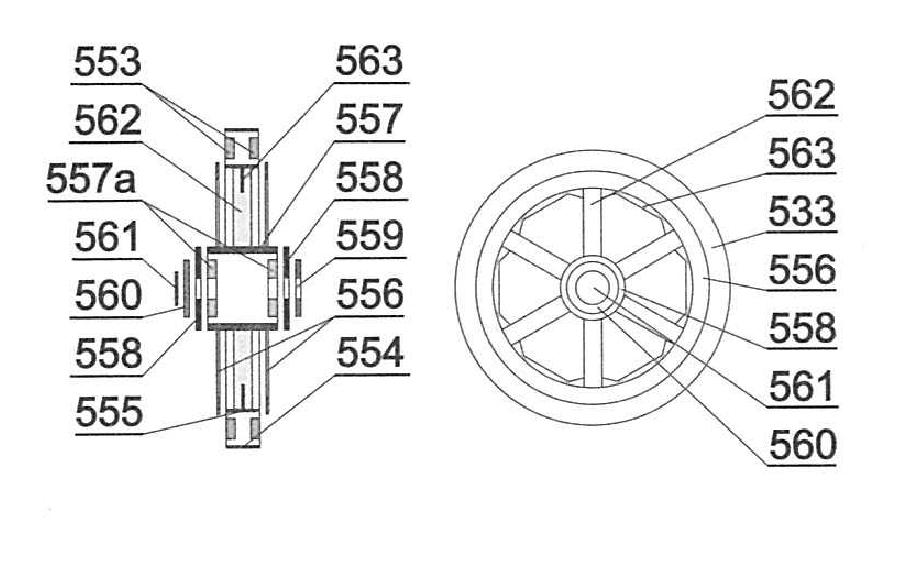
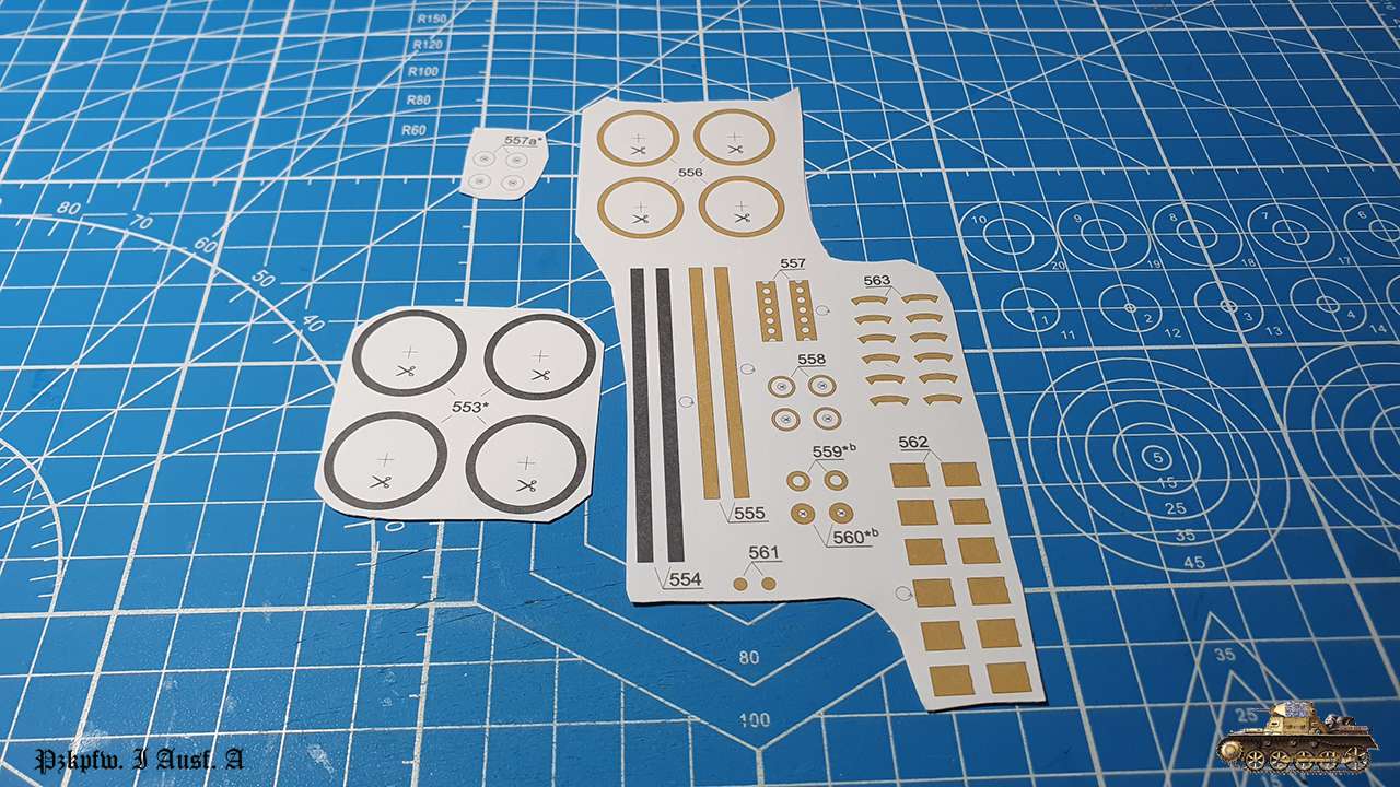
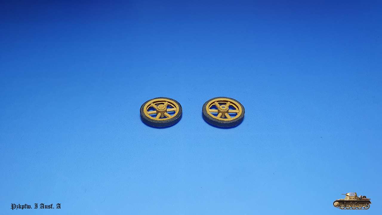
Errors:
Didn't decide yet")
First two front wheels.
I struggled with those and still don't understand if it is my mistake or design flaw.
I cut inner ring diameter precisely, but inner strip was half mm big and afterwards wheels spokes didn't match in it. So, I was in need to adjust one by one.
By default, spokes are hit and miss, because you cannot assemble 100% perfect. But here it was a real issue.
Later will be more wheels and I'll do an experiment with first one to understand what's wrong.
Errors:
Didn't decide yet
Last edited:
Hi all
Continue straggling with suspension.
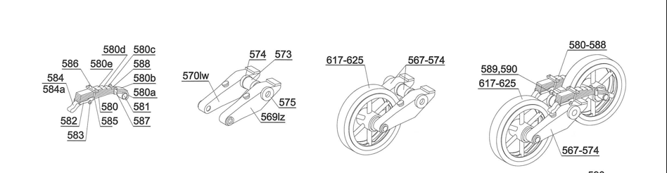
Assembled front suspension lever mechanism, except wheels.
Front rocker levers - designed well, but there was a mistake with mirroring part. Luckly it won't be seen.
Rear springs - many small parts and very fragile construction, because connected only by one rod. Everywhere were i could, i glue with super glue gel for strength
Assembled together. Though connecting points are tiny (and that weird), supporting device (comes in the kit) with exact positioning holes was very helpful.
Final result a bit fragile, but on base rods and with wheels attached - I hoped it will strengthen the whole construction.
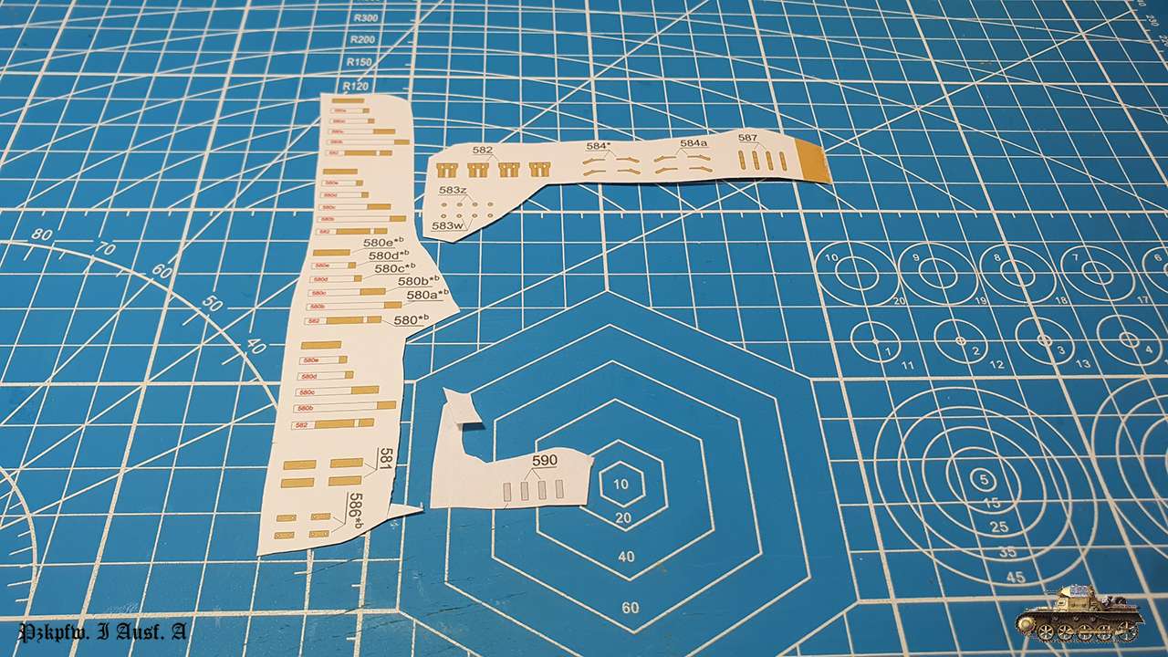
Now repeat almost the same with rear suspension
Errors:
Part 569lz and 570lz confused in design of gluing marks - eventually will not been seen.
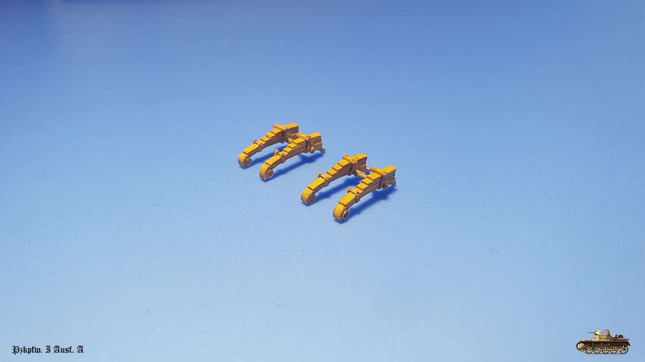
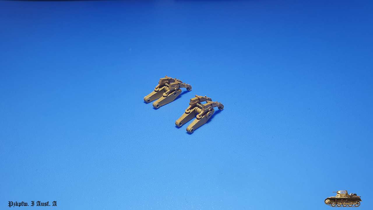
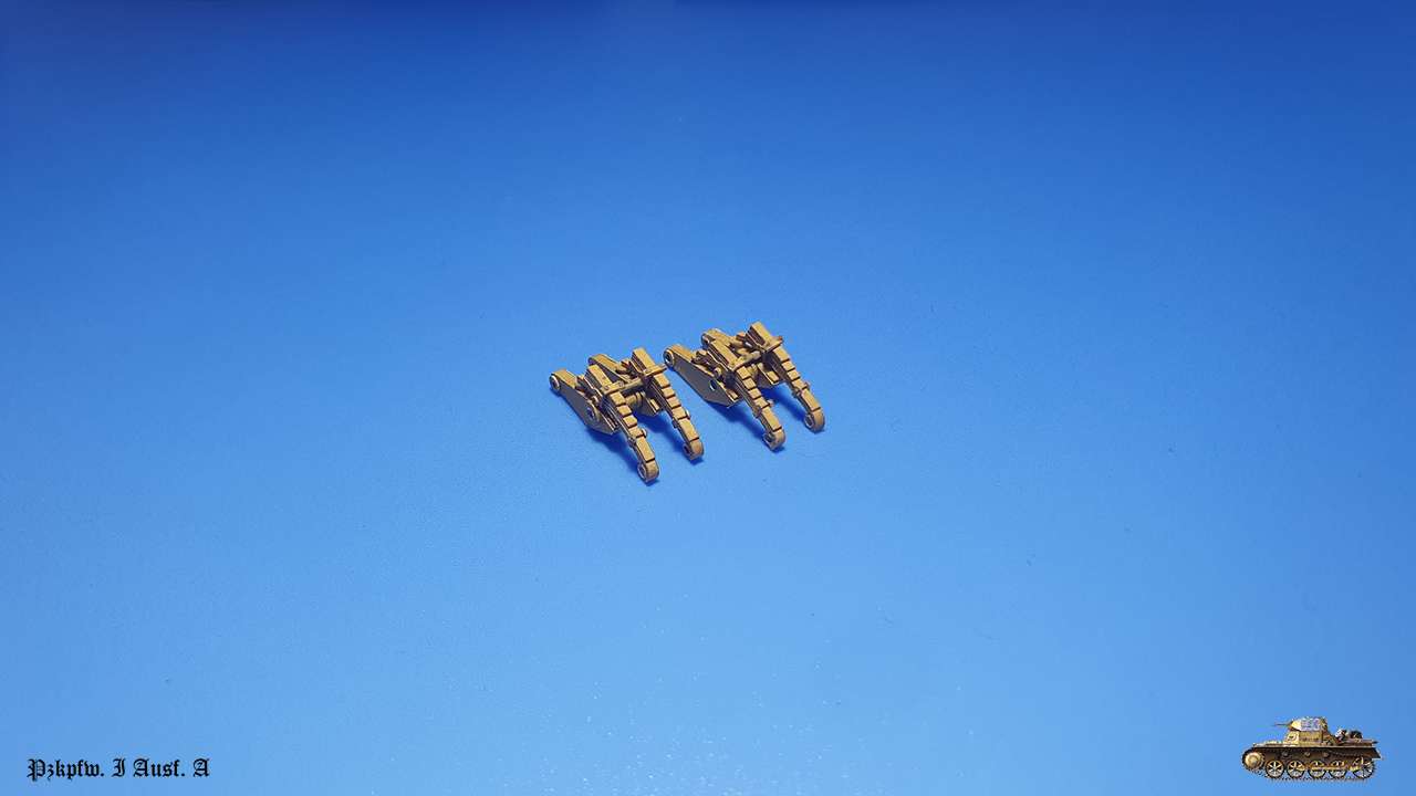
Continue straggling with suspension.
Assembled front suspension lever mechanism, except wheels.
Front rocker levers - designed well, but there was a mistake with mirroring part. Luckly it won't be seen.
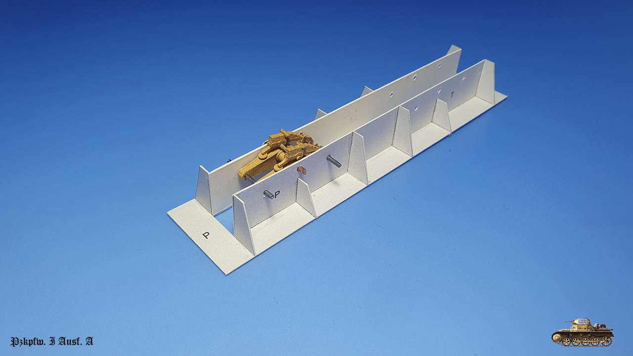
Rear springs - many small parts and very fragile construction, because connected only by one rod. Everywhere were i could, i glue with super glue gel for strength
Assembled together. Though connecting points are tiny (and that weird), supporting device (comes in the kit) with exact positioning holes was very helpful.
Final result a bit fragile, but on base rods and with wheels attached - I hoped it will strengthen the whole construction.
Now repeat almost the same with rear suspension
Errors:
Part 569lz and 570lz confused in design of gluing marks - eventually will not been seen.
Last edited:
- Apr 5, 2013
- 13,498
- 9,549
- 228
I, when very young, used to make leaf springs, wielding a 25 lb. hammer, with a double pointed anvil, and forge to heat the springs red hot, then banging them into the radius needed, I would make leaf springs for cars, trucks, and even huge 3,600 lb units, for the double axle earth movers. These parts you are making look like the real thing. It struck me as to their authenticity. The details is astounding. These are leaf springs, in all their glory, in miniature.
Wow!
Wow!
Last edited:
I gathered the will and got back to the model... At least it gives some escapism.
So, continued with rear suspension levers and springs
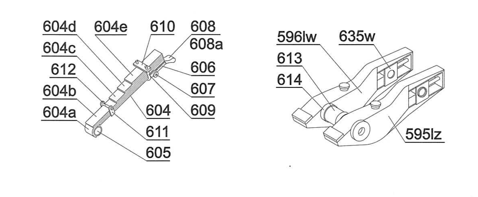
Rocker lever and tension mechanism. There was some odd numbering in parts: part 602 belongs to tension mechanism that has later group of numbers, but was in a rocking lever group. It is a ring that glued on part 365z.
At least there was no error with mirroring parts.
Supporting device help a lot with positioning tension mechanism.
Springs
Assembled together. As with front one, here also final assembly was very fragile. Hope wheels will help to strengthen things
Errors:
Part 602 in wrong numbering group.
Part 604 not signed to glue on a bristol, like it should.
So, continued with rear suspension levers and springs
Rocker lever and tension mechanism. There was some odd numbering in parts: part 602 belongs to tension mechanism that has later group of numbers, but was in a rocking lever group. It is a ring that glued on part 365z.
At least there was no error with mirroring parts.
Supporting device help a lot with positioning tension mechanism.
Springs
Assembled together. As with front one, here also final assembly was very fragile. Hope wheels will help to strengthen things
Errors:
Part 602 in wrong numbering group.
Part 604 not signed to glue on a bristol, like it should.
Thanks friends!
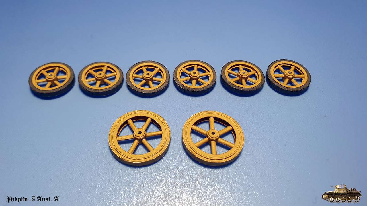
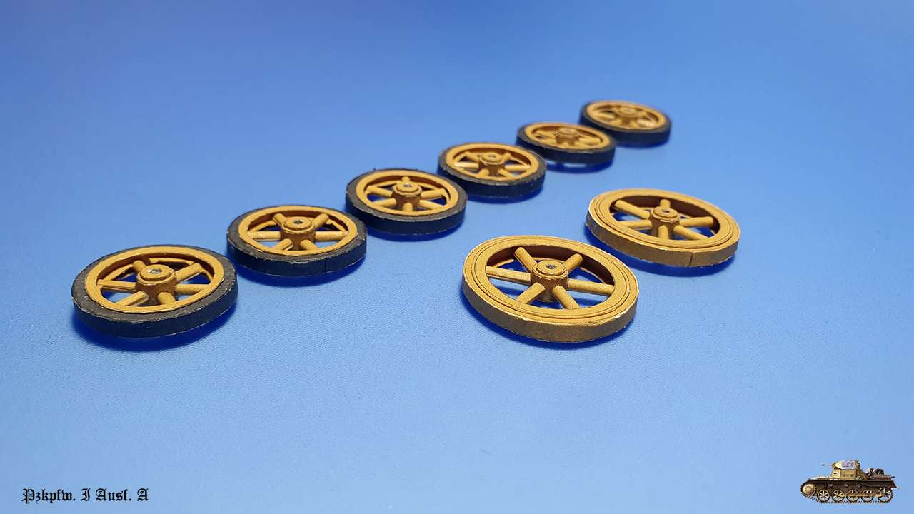
Wheels struggling is finished.
As I was afraid - all six main wheels were designed with errors. This excludes the other two bigger rear tension wheels.
I assume there was a mistake in wheel diameter corresponding to scale, so it was reduced a little... but all other parts were not corrected, so inner strip was too big by half mm and as a result all spokes were too long.
I solved it by first assembling wheel ring and spokes drum, measuring inner ring diameter and drum diameter, subtracting one from another and dividing by 2. This gave my real spoke length and it was short by third mm from original.
I cut all spokes corresponding to new calculation and it did the job.
Main wheel
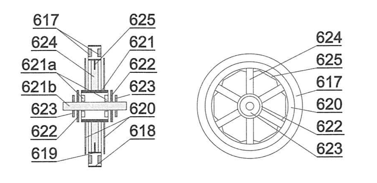
Rear tension wheel
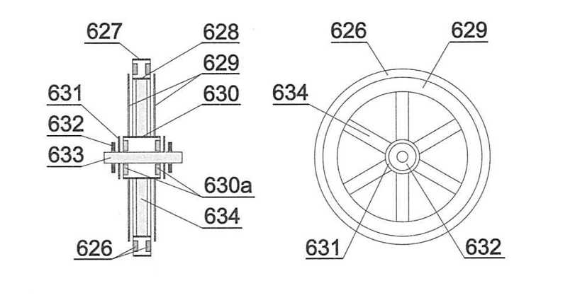
Erros:
Parts 619, 624 too long
Part 632 must by glued on bristol, but has no asterisk sign
Wheels struggling is finished.
As I was afraid - all six main wheels were designed with errors. This excludes the other two bigger rear tension wheels.
I assume there was a mistake in wheel diameter corresponding to scale, so it was reduced a little... but all other parts were not corrected, so inner strip was too big by half mm and as a result all spokes were too long.
I solved it by first assembling wheel ring and spokes drum, measuring inner ring diameter and drum diameter, subtracting one from another and dividing by 2. This gave my real spoke length and it was short by third mm from original.
I cut all spokes corresponding to new calculation and it did the job.
Main wheel
Rear tension wheel
Erros:
Parts 619, 624 too long
Part 632 must by glued on bristol, but has no asterisk sign
Finaly finished with this disaster...
I have to admit this was the worst experience in building suspension the I had.
Apart from problems with wheels, rocking levers and springs had no strong points of joint and tended to break apart whole time of assembling.
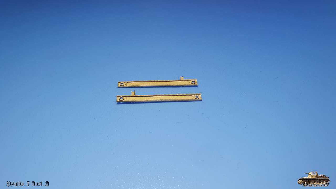
Supporting rods base, despite that it was glued with super glue, fall apart to layers all the time.
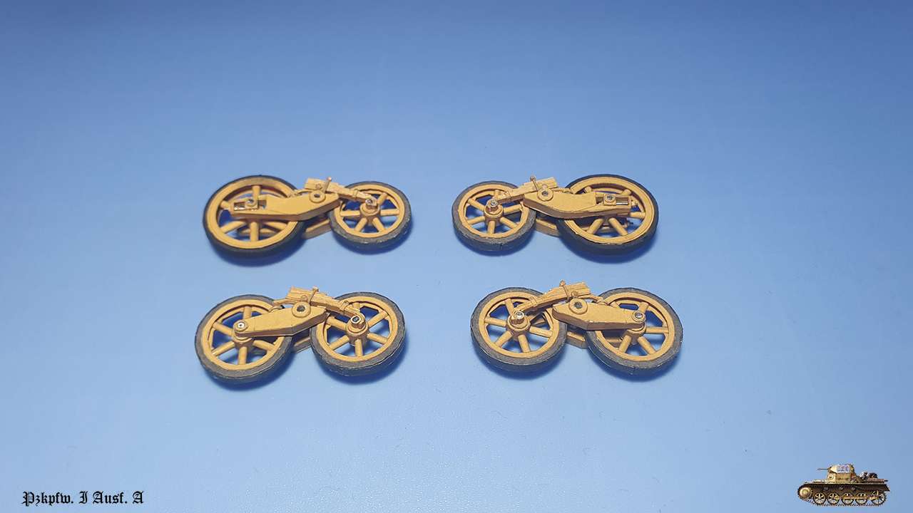
Eventually I managed somehow to glue it all together and make the tank stand fairly straight, but wheels on spring now work only as decorative - the body stands on rocking levers wheels only.
Pay attention, to put dry fit front wheel first. Later it wheel be difficult, though you need to glue it last, to prevent putting all the weight on single wheel.
Also, fellow member on other forum pointed out that idler wheels must also be with rubber bandages, so I painted those in black.
You can see it here.
Wheels and connecting beams assembled.
Everything put together.
Next are trаcks. Wish me luck
Errors:
part 626 not painted as part 617, to imitate rubber bandage.
I have to admit this was the worst experience in building suspension the I had.
Apart from problems with wheels, rocking levers and springs had no strong points of joint and tended to break apart whole time of assembling.
Supporting rods base, despite that it was glued with super glue, fall apart to layers all the time.
Eventually I managed somehow to glue it all together and make the tank stand fairly straight, but wheels on spring now work only as decorative - the body stands on rocking levers wheels only.
Pay attention, to put dry fit front wheel first. Later it wheel be difficult, though you need to glue it last, to prevent putting all the weight on single wheel.
Also, fellow member on other forum pointed out that idler wheels must also be with rubber bandages, so I painted those in black.
You can see it here.
Wheels and connecting beams assembled.
Everything put together.
Next are trаcks. Wish me luck
Errors:
part 626 not painted as part 617, to imitate rubber bandage.
Last edited: