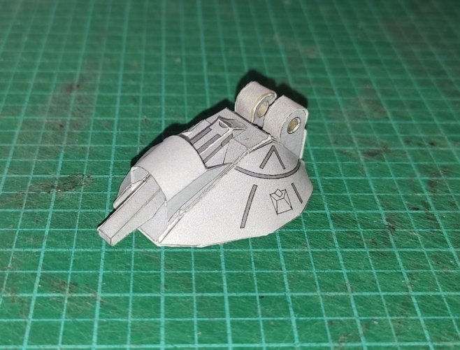
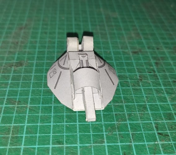
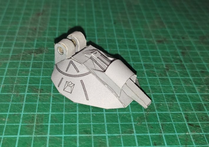
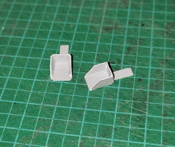
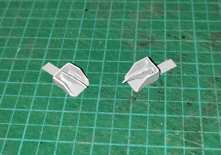
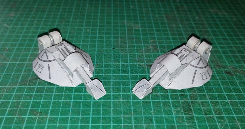
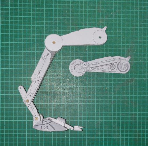
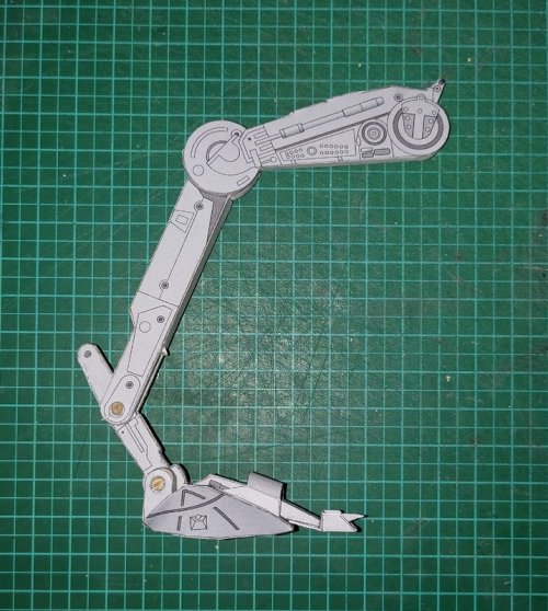
Pick your chicken (Imperial edition) ;-)

Revell-Fan

Co-Administrator
Staff member
Administrator
Moderator
Aug 1, 2009
11,611
12,352
228
Vreden
Thank you all! Sometimes I'm so carried away during building that I forget to take follow-up pictures. However, since everything is still a WIP I still have a chance to take them later. :)

This is a comparison of the old (red) and the new (green) toe section:

13.jpg

This should work better. :)
 

Revell-Fan

Co-Administrator
Staff member
Administrator
Moderator
Aug 1, 2009
11,611
12,352
228
Vreden
Now we have a problem. I told you about some trouble with the engine block B-2 and the rear cap B-1.

15.jpg

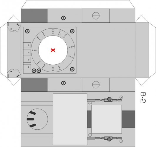
B-2 got a much more sophisticated texture. I added a rectangle, several bolts and hose connectors and a ring around the hole with several circles inside. The rear cap covers quite a bit of the new texture when it is attached as intended. If you move it further back so that the texture is not affected there is no surface where you can glue it to.

I too noticed that the chin needs some more leeway to rotate without hitting the box. I guess this was the reason why Shunichi chose to mount the head at an angle, to keep the chin out of the way.

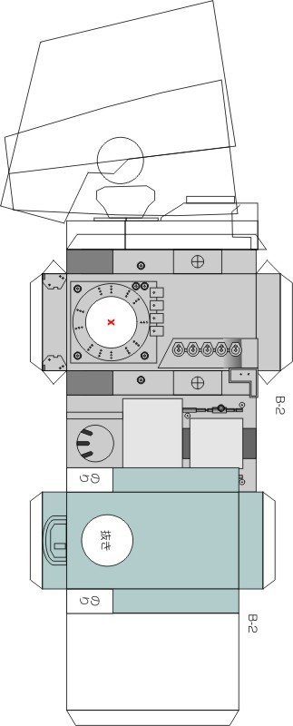
To make the cap fit I would have to prolongue the engine box even more. It already is pretty long and the finished assembly would be longer than it should be. I was curious to find out what the problem was. So I made a quick sketch of the side view of the Bandai model and saw this:

14.jpg

The oiginal neck tube from Shunichi was too big which lead to an out-of-scale texture. The length of the engine box was just fine. However, you can also see that the original position of the neck tube was a bit too close to the front. I found this not too bad because it would make sure that the head won't hit anything. To make room for the texture I moved the hole back which resulted in the lack of leeway, so the neck position had to change back to its original configuration.

That in turn led to a more severe issue: The texture would not fit any longer because of the reduced space at the front. I don't want to toy with the neck tube and resize it to an actual in-scale size without being certain that this does not lead to an unstable mount. In addition, the diameter would shrink to about 1 cm which would make the assembly a bit fiddly.

So I had to come up with a reasonable solution without sacrificing too much of the work that had already gotten into this project.

To make a long story short: I simply rotated the texture plate by 180° and shortened the rectangle. Instant fit. The hole for the tube sits closer to the front again now but not as close as on Shunichi's original kit, the ring texture around the hole is saved and the rear cap can be attached as intended. I may revisit this piece in the future and make an even more accurate kit but for now this should do. :)
 
Last edited:

Revell-Fan

Co-Administrator
Staff member
Administrator
Moderator
Aug 1, 2009
11,611
12,352
228
Vreden
:)

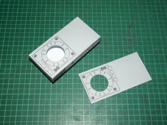
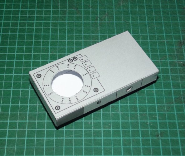
The fix on the real part:

DSCF1783.jpg

The revised plate with the rotated texture is simply glued to the top side of the box. Everything else stays the same, so there was no need to build an all-new box. ;)

DSCF1784.jpg

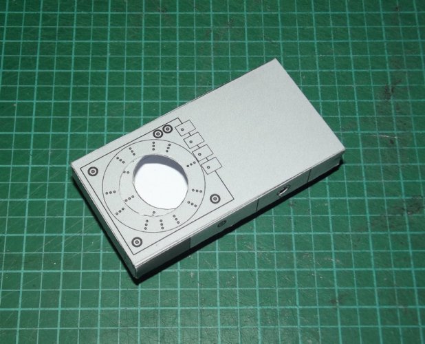
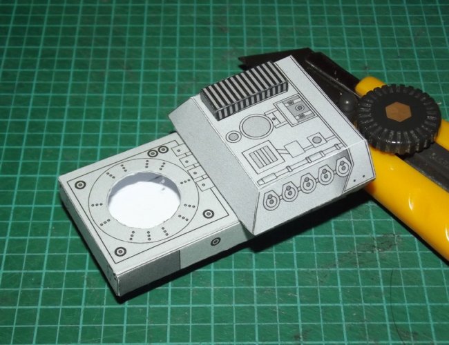
Here you can see how far the neck position is moved forward.

DSCF1785.jpg

The superfluous flesh was cut off.

DSCF1786.jpg

A quick dry-fit of the rear cover B-1 shows that the texture will be visible on the finished part - as it should be. ;)


+++ INTERMISSION +++


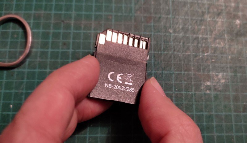
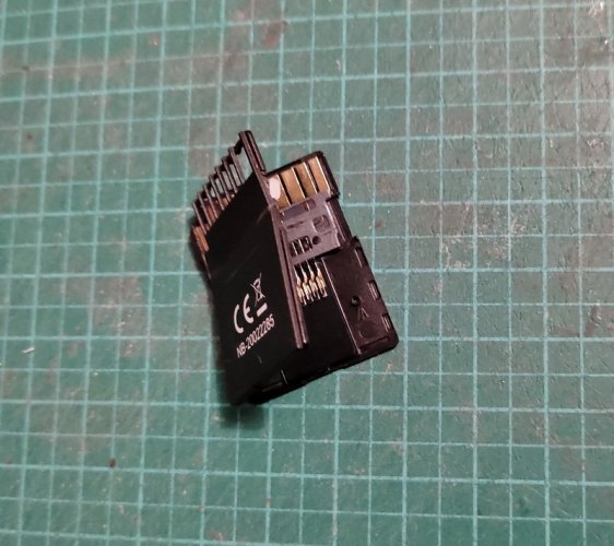
When I removed the SD card from my cam and put it into the SD slot of my lappie I must have applied "slightly" too much pressure. All of a sudden the housing snapped and became unusable.

1669315729641.jpg

1669315729664.jpg

Luckily I was still able to connect the card to the lappie using a card reader and to salvage the build pics of the engine box fix.

Till I have got a new one I'll have to take pictures with my phone. Ah well.

1669315729675.jpg

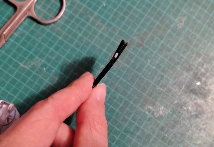
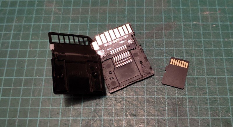
HOWEVER: Upon closer inspection I found out that there was a fully functional micro SD card inside.

1669320150497.jpg

Since it was only the shell that cracked I'll be using that micro card to enhance the storage space of my phone. CU later! :)
 
Last edited:

micahrogers

Moderator "Where am I, and how did I get here?"
Staff member
Moderator
Jul 12, 2012
3,772
4,639
113
Shannon GA
:)

The fix on the real part:

View attachment 208264

The revised plate with the turned texture is simply glued to the top side of the box. Everything else stays the same, so there was no need to build an all-new box. ;)

View attachment 208265

Here you can see how far the neck position is moved forward.

View attachment 208266

The superfluous flesh was cut off.

View attachment 208267

A quick dry-fit of the rear cover B-1 shows that the texture will be visible on the finished part - as it should be. ;)


+++ INTERMISSION +++


When I removed the SD card from my cam and put it into the SD slot of my lappie I must have applied "slightly" too much pressure. All of a sudden the housing snapped and became unusable.

View attachment 208260

View attachment 208261

Luckily I was still able to connect the card to the lappie using a card reader and to salvage the build pics of the engine box fix.

Till I have got a new one I'll have to take pictures with my phone. Ah well.

View attachment 208262

HOWEVER: Upon closer inspection I found out that there was a fully functional micro SD card inside.

View attachment 208263

Since it was only the shell that cracked I'll be using that micro card to enhance the storage space of my phone. CU later! :)
Just don't think you can use it in a Samsung Galaxy S22, series, no more SD slots in them.
 
  • Wow
Reactions: mijob

Revell-Fan

Co-Administrator
Staff member
Administrator
Moderator
Aug 1, 2009
11,611
12,352
228
Vreden
Usually I do not get too excited by the Black Friday frenzy but today I discovered some nice deals on Amazon. I got myself the TVC Nevarro Cantina for 38 bucks which is almost half the original retail price in Germany. I have been keeping an eye on the accessories that come with it because I believe they can be used nicely in Jabba's Boba's palace, especially the broken bowl. :drinksmile: To make the order count I added a new 32GB SD card to my shopping cart for a whopping 8 €, so everything is fine. ;)
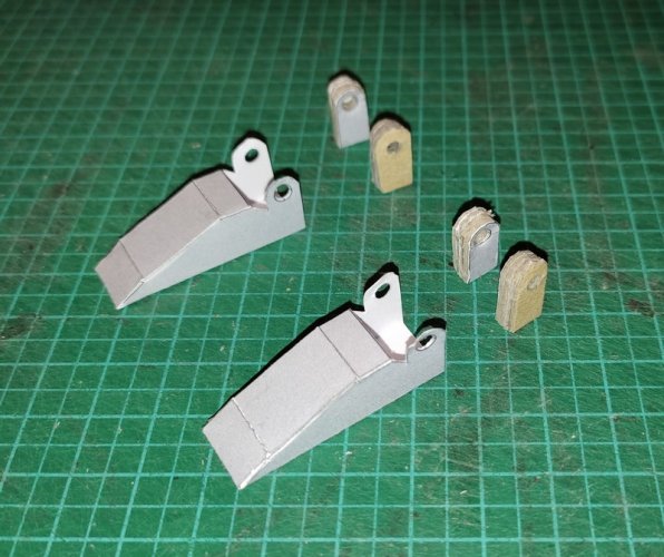
Tilll my Fuji is fully operational again I'll have to get used to take pictures with my phone under less than ideal conditions. I hope they don't come out too horribly. :)

The redrawn feet look quite nice. To make them line up with my revision of Shunichi's original design it was necessary to beef up the calfs a bit. I have separated the back sides which were originally connected to momirfarooq's center leg piece and laminated them to several layers of card.
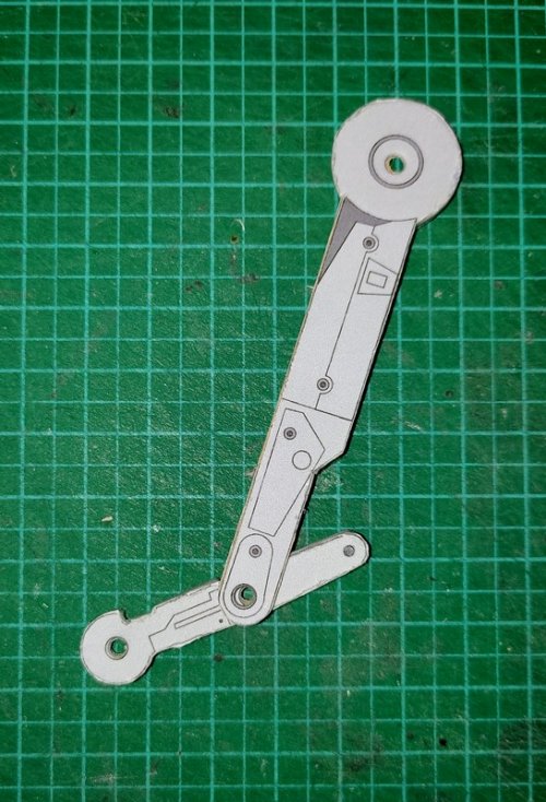
1669408622369.jpg

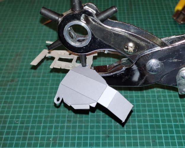
Each layer was punched separately which worked nicely and prevented the holepunch from clogging up. Please note the "sacificial layer" beneath the part to ensure a perfect punch.

1669408622386.jpg

A quick and dirty test fit of calfs and heel:

1669408622421.jpg

1669408622403.jpg

That looks like a good fit. However, if you glue the laminated parts to the foot now the sides will stand out in a very ugly way:

1669408622254.jpg

Something has to be done to cover this "mess" up. ;)

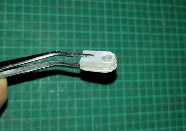
Now comes a step I was looking forward to since I started this project. Shunichi used paper strips to conceal several open areas which I found ingenious and elegant. I copied this technique with a twist: Basically you are free to laminate the leg parts to any thickness you desire. I chose a thickness of about 2.5 - 3mm. There is no right or wrong, I only give a recommendation. However, if you have picked one specific thickness it is very important that you keep this value for all parts for a consistent look and to make sure that the heel can be inserted into the fork-like part of the lower leg. It is important to constantly test-fit the heel and the calfs so that you do not add too much card. If you laminate the heel thicker you will have to compensate this by laminating the calfs thinner. In the end every builder may end up with varying thicknesses of the calfs and leg pieces. So how do you determine the width of the cover needed?

You could get some calipers, draw some parallel lines on a sheet of grey paper, cut it, measure again etc. OR you could do it like THIS:

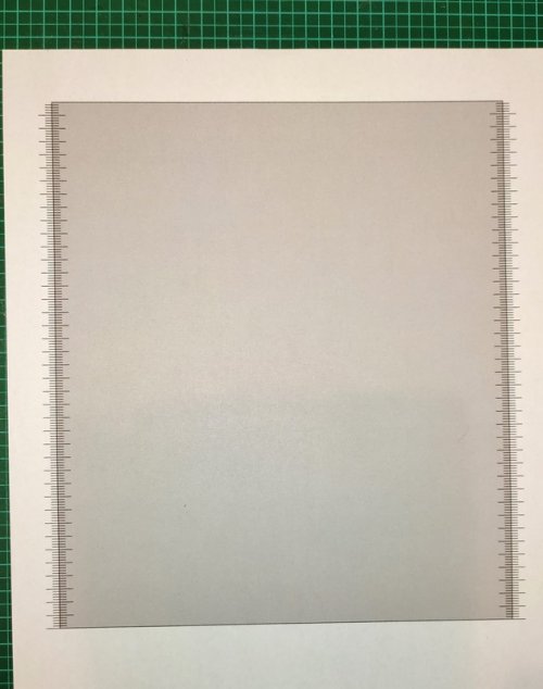
Print a big grey rectangle framed by a set of rulers onto a sheet of regular paper:

1669408622353.jpg

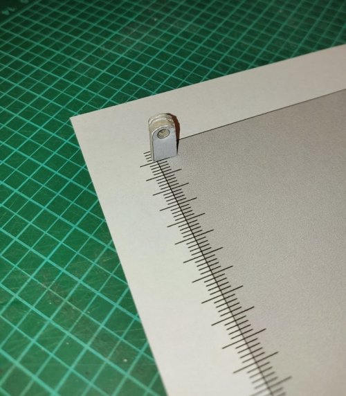
Place the calfs piece onto one edge to see how wide the cover needs to be:

1669408622336.jpg

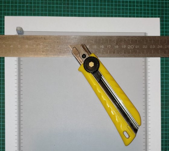
Take a ruler and connect the neighbouring edge:

1669408622320.jpg

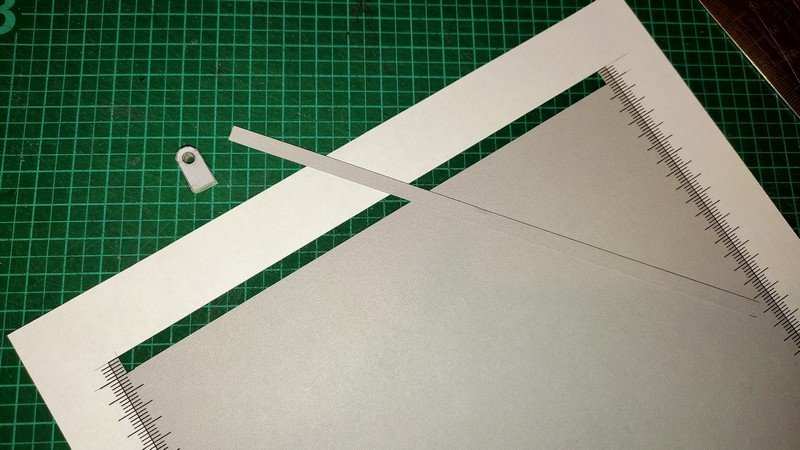
Cut out a long strip (and remove any sign of the ruler lines):

1669408622298.jpg

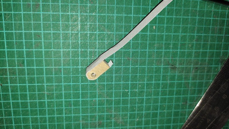
Apply some glue to the edge of the calfs part and wrap the strip around the edge:

1669408622278.jpg

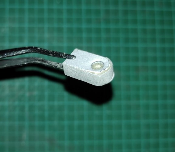
Cut off any excess and you have THIS:

1669408622265.jpg

A clean edge without visible laminations. Attach the parts:

1669408622243.jpg

DONE! :)
 
Last edited:

Revell-Fan

Co-Administrator
Staff member
Administrator
Moderator
Aug 1, 2009
11,611
12,352
228
Vreden
Work on the feet continues:

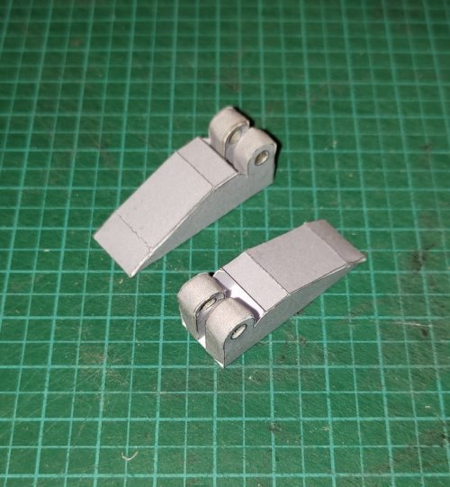
1669423040624.jpg

When I started redrrawing the bottom I mirrored the texture for the other side. However, then I noticed that both feet on the Bandai have the same look. For this reason I simply doubled them. So if you see two of the same feet in the final kit you do not have to worry. This is no mistake. :)

1669577162569.jpg

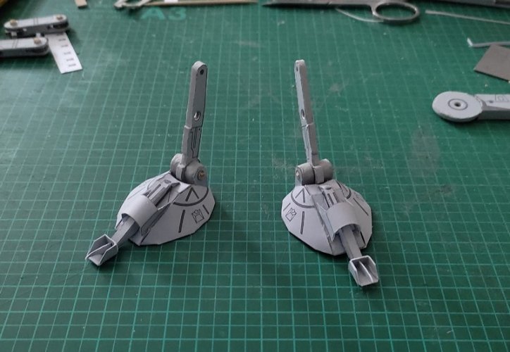
Basic assembly follows momirfarooq's instructions. He did a great job in making the feet. The unconventional design captures the look and feel of the original miniature fairly well.

1669577162558.jpg

1669577162545.jpg

1669577162534.jpg

1669577162521.jpg

1669577162500.jpg

1669577162481.jpg

1669577162464.jpg

1669577162442.jpg

1669577162420.jpg

1669577162396.jpg

1669577162370.jpg

1669577162344.jpg

1669577162325.jpg

1669577162298.jpg

And done! :)
 
Last edited:

Revell-Fan

Co-Administrator
Staff member
Administrator
Moderator
Aug 1, 2009
11,611
12,352
228
Vreden
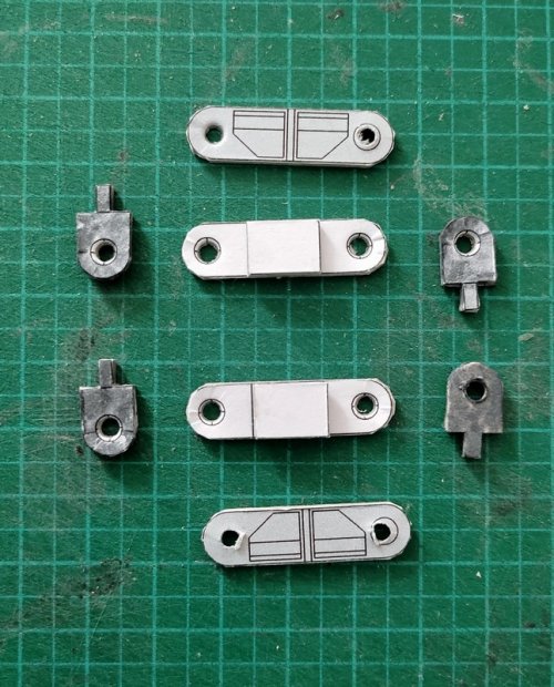
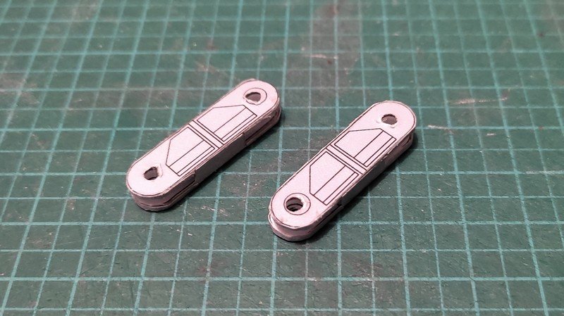
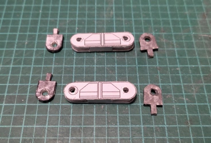
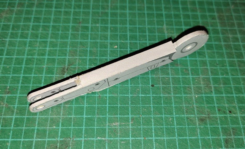
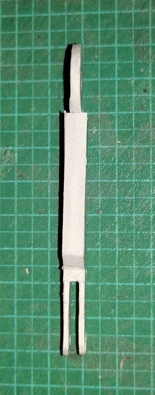
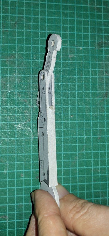
Now we come to the hip joints. They are laminated pieces which are covered by the grey paper strips as mentioned above.

1669577162243.jpg

1669577162224.jpg

1669577162202.jpg

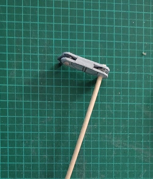
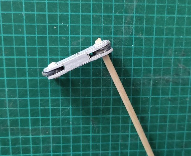
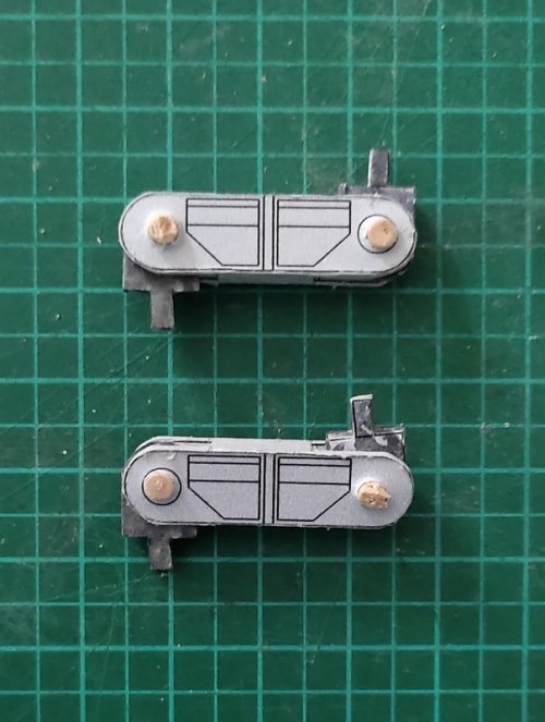
The parts are jointed:

1669577162105.jpg

1669577162083.jpg

1669577162064.jpg

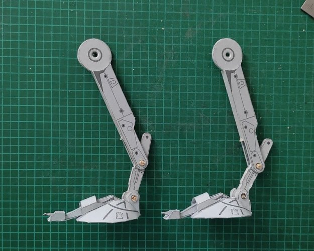
And as promised the additional pictures of the lower leg parts:

1669423040695.jpg

1669423040683.jpg

1669423040669.jpg

1669423040657.jpg

1669423040645.jpg

1669423040634.jpg

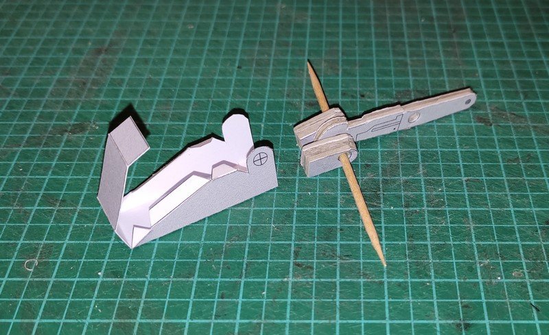
All elements are connected using rods:

1669577162039.jpg

1669577162015.jpg

1669577161987.jpg

1669423040706.jpg

Front and back side of the upper leg.

1669577161958.jpg

This end of the rod is cut down flush.

1669577161905.jpg

Now comes the cover:

1669577161880.jpg

And one leg is DONE! The other one is assembled accordingly. :)
 
Last edited: