

"PaperLaul's Terminator 2: Hunter Killer Aerial - by DanBKing"
- Thread starter DanBKing
- Start date
You are using an out of date browser. It may not display this or other websites correctly.
You should upgrade or use an alternative browser.
You should upgrade or use an alternative browser.
- Status
- Not open for further replies.
The answer is always 42, we're just not asking the right question.
thumbsup
thumbsup

 Claphands
- Apr 5, 2013
- 13,876
- 10,215
- 228
Dan, it looks like one really strong frame your making there. That's great and a great lesson for people. The models future will be secured with this strong foundation. ")
Let there be light ...... !
Because I needed to be sure of how I was going to run the wiring within the model, I decided to start working on the sub-assemblies that will contain lighting. If I go any further with the fuselage, I wont be able to get inside to wire everything up.
So, first up: The spot/search lights on the front of the model.
I decided to use high intensity white LED's for this job. These LED's already have a spotlight effect, created by the lens of the LED.
I want the spot effect to be enhanced even more. I decided to make a reflector to mount the LED in.
Using an online cone dimensions calculator, found here: http://craig-russell.co.uk/demos/cone_calculator/ I made up a cone from black card. I needed a 6mm hole at the 'point' of the cone, (for the LED) and a 13mm hole at the bottom. The cone needed to be 11mm high.

One side of each piece was covered with a piece of metal foil tape, to create a reflective surface. Then the cones were formed.

Next up, I punched out the textured lens of the spotlight part and replaced it with a piece of clear plastic, punched out from a Christmas card 'box', that I found upstairs. This piece was then glued to the back of the paper lens ring, thereby forming a clear lens.

The inner tube of the searchlight was made up, and then the reflector cone was glued to the tube and the LED installed in the back of the cone.
The back of the LED was coloured in with a black marker to restrict any stray light.
This assembly was then attached to the back of the lens ring, with the clear plastic in between.

The upper part of the spotlight was made up next. Because I am painting the model, I would lose the texturing of the part, so this had to be 'greebled' to create the 3D texture. I cut/punched out the texture and glued a copy of the corresponding piece to the back of this. While the glue was still wet, the part was formed to shape and allowed to dry.

Because I wanted the ability to aim the spotlights, I decided to make swivel-able mountings, instead of the fixed ones provided in the kit.
I punched out the correct size holes in the upper shroud. And as usual in my builds, I found a build aid, in an ink tube of a ball point pen of the correct diameter for the swivel posts. As these posts fit the ink tube snuggly, I am going to use small offcuts of the ink tube, (without ink in!,) for the posts to swivel on.
I tacked the posts in position and will adjust these later, upon installation to the fuselage.


The LED was then wired up and the sub-assemblies were glued together. The wiring from the LED runs through one of the pivot tubes, to the outer world.

And this, ladies and gentlemen (and others ,) is the end result!

In the next photo, the spotlights are held about 30cm (1ft) above the cutting mat. A nice solid beam! Just what I was hoping for.

More soon!

Because I needed to be sure of how I was going to run the wiring within the model, I decided to start working on the sub-assemblies that will contain lighting. If I go any further with the fuselage, I wont be able to get inside to wire everything up.
So, first up: The spot/search lights on the front of the model.
I decided to use high intensity white LED's for this job. These LED's already have a spotlight effect, created by the lens of the LED.
I want the spot effect to be enhanced even more. I decided to make a reflector to mount the LED in.
Using an online cone dimensions calculator, found here: http://craig-russell.co.uk/demos/cone_calculator/ I made up a cone from black card. I needed a 6mm hole at the 'point' of the cone, (for the LED) and a 13mm hole at the bottom. The cone needed to be 11mm high.
One side of each piece was covered with a piece of metal foil tape, to create a reflective surface. Then the cones were formed.
Next up, I punched out the textured lens of the spotlight part and replaced it with a piece of clear plastic, punched out from a Christmas card 'box', that I found upstairs. This piece was then glued to the back of the paper lens ring, thereby forming a clear lens.
The inner tube of the searchlight was made up, and then the reflector cone was glued to the tube and the LED installed in the back of the cone.
The back of the LED was coloured in with a black marker to restrict any stray light.
This assembly was then attached to the back of the lens ring, with the clear plastic in between.
The upper part of the spotlight was made up next. Because I am painting the model, I would lose the texturing of the part, so this had to be 'greebled' to create the 3D texture. I cut/punched out the texture and glued a copy of the corresponding piece to the back of this. While the glue was still wet, the part was formed to shape and allowed to dry.
Because I wanted the ability to aim the spotlights, I decided to make swivel-able mountings, instead of the fixed ones provided in the kit.
I punched out the correct size holes in the upper shroud. And as usual in my builds, I found a build aid, in an ink tube of a ball point pen of the correct diameter for the swivel posts. As these posts fit the ink tube snuggly, I am going to use small offcuts of the ink tube, (without ink in!,) for the posts to swivel on.
I tacked the posts in position and will adjust these later, upon installation to the fuselage.
The LED was then wired up and the sub-assemblies were glued together. The wiring from the LED runs through one of the pivot tubes, to the outer world.
And this, ladies and gentlemen (and others
,) is the end result!In the next photo, the spotlights are held about 30cm (1ft) above the cutting mat. A nice solid beam! Just what I was hoping for.
More soon!
Fly, on the tips of your wings .....
The sets of LEDs on the wingtips are up next.
I don't want the LED's to be too intense for these. Each wingtip has two LED's, one set red, the other blue. Again, high intensity LED's were used, but to diffuse the light beam and soften the 'glare', I spent about 5 minutes on each LED with a piece of 400 grit wet&dry paper, until the surface was opaque and dusty in appearance. The dust was then cleaned off under running water.
You can see the difference to the light, from a sanded and normal LED in this pic .....

The tubes that make up the wing tips are around 7mm diameter. The LED's are 5mm diameter.
Using thin strips of stickers, I wrapped the backs of the LED's up to the inner diameter of the tubes, with progressively thinner strips, to create a smoother transition.
The sticker strips and backs of the LED's were then coloured with a black marker.

I still need to glue the LED's in position (one has popped out on the upper tube,) but the effect is good.

Well, now that these are done, I have to build the wings to attach them to!!!
But, anyway, two out of four lighting sets are now complete.
The only other assemblies containing lighting is the fuselage, (simple) and the engines, (complex!)...........
I have started working on one engine, as a test bed. The first engine, (and subsequent,) is going to undertake some MAJOR modifications, and will also be a good testing ground for my panelling/greebling technique. We will see how that turns out.
I have a busy weekend ahead, so I hope to post some more early next week.
HAVE A GREAT WEEKEND, EVERYBODY!!!!!!
The sets of LEDs on the wingtips are up next.
I don't want the LED's to be too intense for these. Each wingtip has two LED's, one set red, the other blue. Again, high intensity LED's were used, but to diffuse the light beam and soften the 'glare', I spent about 5 minutes on each LED with a piece of 400 grit wet&dry paper, until the surface was opaque and dusty in appearance. The dust was then cleaned off under running water.
You can see the difference to the light, from a sanded and normal LED in this pic .....
The tubes that make up the wing tips are around 7mm diameter. The LED's are 5mm diameter.
Using thin strips of stickers, I wrapped the backs of the LED's up to the inner diameter of the tubes, with progressively thinner strips, to create a smoother transition.
The sticker strips and backs of the LED's were then coloured with a black marker.
I still need to glue the LED's in position (one has popped out on the upper tube,) but the effect is good.
Well, now that these are done, I have to build the wings to attach them to!!!
But, anyway, two out of four lighting sets are now complete.
The only other assemblies containing lighting is the fuselage, (simple) and the engines, (complex!)...........
I have started working on one engine, as a test bed. The first engine, (and subsequent,) is going to undertake some MAJOR modifications, and will also be a good testing ground for my panelling/greebling technique. We will see how that turns out.
I have a busy weekend ahead, so I hope to post some more early next week.
HAVE A GREAT WEEKEND, EVERYBODY!!!!!!

 )
)The swivel joints for the engines have already been rolled! ")
I did a little more on the engine last night. I can't wait to show you guys the end result........
I did a little more on the engine last night. I can't wait to show you guys the end result........
Exhausting...!
The next assemblies that contain lighting are the exhaust ports of the engines.
The exhausts are vented and I wanted this to be apparent whether the engines were lit, or not.
So, I printed out a copy of the engine parts on 80gsm paper. As I wanted the vanes to be slightly smaller than the original, I printed the page at 2% smaller.
I then put two blades together in my cutter handle, and utilized the resulting gap between the blades, to cut the printed lines from between the vanes .....

I then cut a disc of clear plastic to match the outer diameter of the exhaust port tube.
I used a semi-translucent folder cover, and punched out two pieces of this. These pieces I glued together and then these were glued dead centre to the plastic disc.

Using my trusty circle template, to align things and provide uniform pressure, I glued the outer edges of the vanes to the plastic disc.
By using a small hole, the points of the vanes are forced upwards, against the center piece...

By using gentle and even finger pressure, the points were persuaded to shape over the centre piece.

A centre disc was punched out and glued on top of the points of the vanes. When the template is removed, the middle of the vane pieces spring back, giving a nice form and shape.
And this is the resulting shape, with nice spaces between the vanes to let the light through.

Using the same system as for the spotlights, I made up a reflective light cone and glued a blue high intensity LED into the point.
The vane assembly was trimmed to size and sandwiched and glued, between the exhaust tube and the light cone. I used black electrical tape to seal and hold everything tight.

I wired up the LED and this is how it looks .....
The first pic is with the camera flash on, the others, not.


And I really like the 'jet blast' effect of the projected light.......

I am SUPER pleased with that .......:King:
More soon .......
The next assemblies that contain lighting are the exhaust ports of the engines.
The exhausts are vented and I wanted this to be apparent whether the engines were lit, or not.
So, I printed out a copy of the engine parts on 80gsm paper. As I wanted the vanes to be slightly smaller than the original, I printed the page at 2% smaller.
I then put two blades together in my cutter handle, and utilized the resulting gap between the blades, to cut the printed lines from between the vanes .....
I then cut a disc of clear plastic to match the outer diameter of the exhaust port tube.
I used a semi-translucent folder cover, and punched out two pieces of this. These pieces I glued together and then these were glued dead centre to the plastic disc.
Using my trusty circle template, to align things and provide uniform pressure, I glued the outer edges of the vanes to the plastic disc.
By using a small hole, the points of the vanes are forced upwards, against the center piece...
By using gentle and even finger pressure, the points were persuaded to shape over the centre piece.
A centre disc was punched out and glued on top of the points of the vanes. When the template is removed, the middle of the vane pieces spring back, giving a nice form and shape.
And this is the resulting shape, with nice spaces between the vanes to let the light through.
Using the same system as for the spotlights, I made up a reflective light cone and glued a blue high intensity LED into the point.
The vane assembly was trimmed to size and sandwiched and glued, between the exhaust tube and the light cone. I used black electrical tape to seal and hold everything tight.
I wired up the LED and this is how it looks .....
The first pic is with the camera flash on, the others, not.
And I really like the 'jet blast' effect of the projected light.......
I am SUPER pleased with that .......:King:
More soon .......
Last edited:
 rinks:
- Apr 5, 2013
- 13,876
- 10,215
- 228
That looks great! Personally, I would paint the back sides of the petals Black, to allow the lights to escape through the slits. They will glow and give the same effect, but will be more pronounced, as they come to the slits. Roger Penrose, the physicist, wrote some interesting work on how light "knows" which way to go.
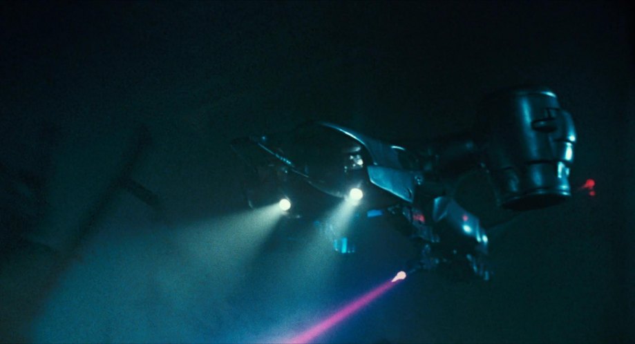
I am of the opinion that there are no lights coming out of these at all because they are not jet engines. They are lift fans, with cross shafts. There push massive volumes of air with the power supplied through shafts. Every pictures I have ever seen, from the movies, I have the whole collection, these Hunter Killers have many spot lights, but none lights from the variable pitch life engines. This is a defensive feature as this gives one less heat source for a missile to grab onto, and by grabbing the surrounding air, in actuality, cools it, there by reducing the crafts overall heat signature. Just a though. The lights looks cool, don't get me wrong. It's just details I noticed, and noticed on other models that have been lit up, have left out also. Even the spot lights are a deception, as the Hunter Killers use FLIR type systems to detect the heat of a humans body. Much like police Helicopters use spot lights when chasing criminals to deceive them into thinking they are looking somewhere else, when in fact, they are using the FLIR (Forward Looking Infrared Radar) to find their heat signature(s), the spot lights are a rouse. By running the lift fans off of rotating housings, they use the power take off in these shafts to run the fans, provide redundancy, reduce the heat signature, and make the overall unit more robust. The main engines heat plume can be reduced, like on the steal fighters, by sucking in surrounding cool air, and dispersing the thrust.These fans lift up 50% of a fully weighed JSF35, they could easily lift a small hunter Killer. All the benefits, none of the drawbacks. I have family that helped develop this engine. It is an amazing work of engineering. It makes the Terminator movies look dated. My 2 cents worth.
The VTOL version of the JSF 35 uses such a fan, they had to pay the Yakolev Flight bureau for the rights, as the then "Soviet Union" did it first. This makes sense for quite a few reasons. The engine can be protected from small arms fire, it's exhaust cooled, and if some blades are shot out of the lift fan, not big deal, they would just blow out the bottom, with the rest still working. If an engine fails, cross shafts would still run both lift fan thrusters.
.PNG)
See below.

I am of the opinion that there are no lights coming out of these at all because they are not jet engines. They are lift fans, with cross shafts. There push massive volumes of air with the power supplied through shafts. Every pictures I have ever seen, from the movies, I have the whole collection, these Hunter Killers have many spot lights, but none lights from the variable pitch life engines. This is a defensive feature as this gives one less heat source for a missile to grab onto, and by grabbing the surrounding air, in actuality, cools it, there by reducing the crafts overall heat signature. Just a though. The lights looks cool, don't get me wrong. It's just details I noticed, and noticed on other models that have been lit up, have left out also. Even the spot lights are a deception, as the Hunter Killers use FLIR type systems to detect the heat of a humans body. Much like police Helicopters use spot lights when chasing criminals to deceive them into thinking they are looking somewhere else, when in fact, they are using the FLIR (Forward Looking Infrared Radar) to find their heat signature(s), the spot lights are a rouse. By running the lift fans off of rotating housings, they use the power take off in these shafts to run the fans, provide redundancy, reduce the heat signature, and make the overall unit more robust. The main engines heat plume can be reduced, like on the steal fighters, by sucking in surrounding cool air, and dispersing the thrust.These fans lift up 50% of a fully weighed JSF35, they could easily lift a small hunter Killer. All the benefits, none of the drawbacks. I have family that helped develop this engine. It is an amazing work of engineering. It makes the Terminator movies look dated. My 2 cents worth.
The VTOL version of the JSF 35 uses such a fan, they had to pay the Yakolev Flight bureau for the rights, as the then "Soviet Union" did it first. This makes sense for quite a few reasons. The engine can be protected from small arms fire, it's exhaust cooled, and if some blades are shot out of the lift fan, not big deal, they would just blow out the bottom, with the rest still working. If an engine fails, cross shafts would still run both lift fan thrusters.
See below.
@zathros Hey! You are not the chief designer of HK's and working currently at Cyberdyne Systems, are you ???? :jawdrop::nailbiting:
Interesting info.
Anyway, the engine (fan) lights, well, let's just call it artistic licence....
Lit engines will work well in hitting home the point, of another diorama/display idea that I have for the model too.
But, until my idea is proven with a test build of something, I will leave the idea of two different, interchangeable display bases/dioramas, right here for now..........
Laters.......
Last edited:
Hey, it's SciFi, so go with it..!

Suck it up!
The intake of the engine is up next .....
The intake part provided in the kit is just one piece of flat paper, with the engine intake detail printed on it, and this is stuck on top of the engine. The part is rather lacking in detail and boring. Besides, when I paint the model, the detail will vanish and all that will be left, is a flat silver disc atop the engine.

Now, that will not do at all. So, time to change things!!
I want it to look something like this ....... (This is an intake from a 747-B)

First, I cut out the part E18, (the intake,) using 160gsm paper. This will act as the base for the forthcoming detail work.
I then printed two extra copies of the same part on 250gsm paper.
The intake fan has 24 separate vanes depicted in the print texture. Using the 250gsm paper, I cut out 24 sets of two vanes. In other words, I cut 12 slices from one part, containing 2 vanes each, and 12 from the other copy. This gave me 24 sets of two vanes.
Then, using the printed texture as a guide, I stuck each vane set, one by one, onto the backing piece.
Each vane set is only stuck to the backing piece by the back edge. The front edge overlaps the previous glued vane by one vane, (or half of the last vane set).
This makes the unglued front edge stick up a little where it overlaps.
When all were done, I had this result....

As mentioned earlier, and as can be seen in this cut from the instructions, part E18 is stuck directly on top of part E17.

I didn't think that looked right, so I decided to reverse it, and stick E17 on E18 instead. This would give the engine more depth.
I cut out part E16, but left the centre intact, as I would be gluing E18 to this. (Plus, the added advantage of not having to attach at least one fiddly ring part! )
Once the whole vane assembly had dried, I punched out the centre of the whole thing with a 13mm punch.
I also punched out a thick piece of card, at the same size, to attach the punched out centre piece to.
I used a small disc of card and glued this to the centre of the punched out vane piece, to finish it off a bit better.
I then cut 2 discs of thick card. These discs were 17mm in diameter, thereby giving a 2mm extra radius around the hole in the centre of the vane assembly.
These two discs were glued together and glued to the centre of part E16. Some parts were blackened up with a marker.

Deciding to do things this way, created even more work to do though. As part E17 is now uppermost, the thickness of 160gsm paper is not going to make a very realistic looking intake cowling, is it ...?!
So, I laminated part E17 to thick card and cut another strip of thick card to match. These strips were glued together and coerced into a ring shape. I did not want to use water shaping on these for fear of the thick cardboard de-laminating. I did use quite a bit of glue though, to make the thing strong when dry.
Once dried, I sanded both edges of the ring, by rubbing on a piece of 400 grit sandpaper laid flat on the table. I placed the palm of my hand on the ring and drew it around on the sandpaper until the edges were flat, square and smooth.
One edge, which will be the upper edge, was sanded to form a nice rounded form, akin to what an intake cowling should look like!

The flat side of the ring was then glued to part E16.
Next up, I finished off the intake by gluing only the outer and centre edges of the vane assembly, to the backing piece with the two discs attached. This pushed up the centre of the vanes in relation to the outside. The small disc was then glued into the hole in the centre and the punched out part of the vanes, was glued to this.
With a careful bit of trimming here and there, the intake assembly was fitted to the inside of the cowling ring.

I am pleased with the end result!
This whole assembly will eventually be glued to the top of the engine main body.
In the next instalment will be the construction of the body shell, and my first exercise of laminating on the panel work to replace the printed texture with laminated 250gsm card.....
See you all soon! ...
The intake of the engine is up next .....
The intake part provided in the kit is just one piece of flat paper, with the engine intake detail printed on it, and this is stuck on top of the engine. The part is rather lacking in detail and boring. Besides, when I paint the model, the detail will vanish and all that will be left, is a flat silver disc atop the engine.
Now, that will not do at all. So, time to change things!!
I want it to look something like this ....... (This is an intake from a 747-B)
First, I cut out the part E18, (the intake,) using 160gsm paper. This will act as the base for the forthcoming detail work.
I then printed two extra copies of the same part on 250gsm paper.
The intake fan has 24 separate vanes depicted in the print texture. Using the 250gsm paper, I cut out 24 sets of two vanes. In other words, I cut 12 slices from one part, containing 2 vanes each, and 12 from the other copy. This gave me 24 sets of two vanes.
Then, using the printed texture as a guide, I stuck each vane set, one by one, onto the backing piece.
Each vane set is only stuck to the backing piece by the back edge. The front edge overlaps the previous glued vane by one vane, (or half of the last vane set).
This makes the unglued front edge stick up a little where it overlaps.
When all were done, I had this result....
As mentioned earlier, and as can be seen in this cut from the instructions, part E18 is stuck directly on top of part E17.
I didn't think that looked right, so I decided to reverse it, and stick E17 on E18 instead. This would give the engine more depth.
I cut out part E16, but left the centre intact, as I would be gluing E18 to this. (Plus, the added advantage of not having to attach at least one fiddly ring part!
)Once the whole vane assembly had dried, I punched out the centre of the whole thing with a 13mm punch.
I also punched out a thick piece of card, at the same size, to attach the punched out centre piece to.
I used a small disc of card and glued this to the centre of the punched out vane piece, to finish it off a bit better.
I then cut 2 discs of thick card. These discs were 17mm in diameter, thereby giving a 2mm extra radius around the hole in the centre of the vane assembly.
These two discs were glued together and glued to the centre of part E16. Some parts were blackened up with a marker.
Deciding to do things this way, created even more work to do though. As part E17 is now uppermost, the thickness of 160gsm paper is not going to make a very realistic looking intake cowling, is it ...?!
So, I laminated part E17 to thick card and cut another strip of thick card to match. These strips were glued together and coerced into a ring shape. I did not want to use water shaping on these for fear of the thick cardboard de-laminating. I did use quite a bit of glue though, to make the thing strong when dry.
Once dried, I sanded both edges of the ring, by rubbing on a piece of 400 grit sandpaper laid flat on the table. I placed the palm of my hand on the ring and drew it around on the sandpaper until the edges were flat, square and smooth.
One edge, which will be the upper edge, was sanded to form a nice rounded form, akin to what an intake cowling should look like!
The flat side of the ring was then glued to part E16.
Next up, I finished off the intake by gluing only the outer and centre edges of the vane assembly, to the backing piece with the two discs attached. This pushed up the centre of the vanes in relation to the outside. The small disc was then glued into the hole in the centre and the punched out part of the vanes, was glued to this.
With a careful bit of trimming here and there, the intake assembly was fitted to the inside of the cowling ring.
I am pleased with the end result!
This whole assembly will eventually be glued to the top of the engine main body.
In the next instalment will be the construction of the body shell, and my first exercise of laminating on the panel work to replace the printed texture with laminated 250gsm card.....
See you all soon! ...


- Status
- Not open for further replies.