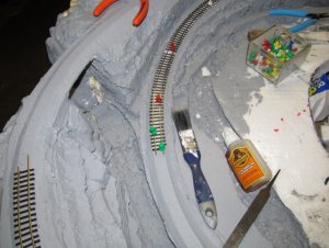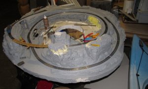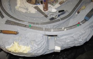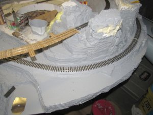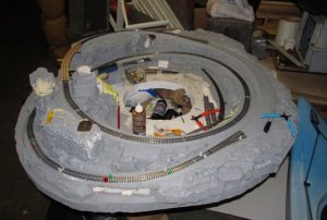
a new mini HON3 layout started

Doctor G

Well-Known Member
Sep 1, 2008
1,415
298
78
Clarksville, Tennessee
More progress. I like your bridge building technique. Holding the curve on the flex track for tracing using two pieces of blue tape is a neat idea.

Looking forward to more info from this nice mini build article.

I used "liquid nails" on my mini to secure the track to the foam. I will be curious to see what you come up with.

Tom
 

Bill Nelson

Well-Known Member
Dec 14, 2008
2,680
467
78
Clarksville Tn
SMLA-1 stringers.jpg started stringers

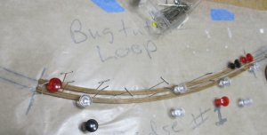
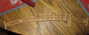
I usually use square beams to build up the stringers for a trestle. the 16 inch radius at one end of the Murray creek trestle on the Bugtusle loop layout was too tight for that and my square timbers kept breaking, as I tried to curve them that tightly. I modified my technique, and laminated four strips of wood , that were cut sized to make profile ties in HO, with tachy glue to make each stringer. and bent them to fit the crayon rubbings on the craft paper. I used pins and tacks to get them to bend to follow the rubbings closely. when they are totally dry, I will add spacers, and glue them in place.


when the whole Assembly is dry I will sand both sides to get it dead flat, and then I will start gluing down bridge ties. Most likely I will cut the bridge ties over sized for added strength, as this trestle will be out there in the breeze during transport, and scale sized ties in Hon3 can be a little fragile.

Once the ties are down I can start spiking rail. I have two #5 Hon3 switches, and I will try to start hooking wires up to them this weekend. I will probably put the bridge and the switches down first, and then start filling in the track in be tween. I'm going to put power feeds at both of the rails on each switch, and feeds on the adjacent inside track. then I will run some little feeder wires around the while layout, so each rail has it's own soldered on power feed.


There is a possibility I may be able to have some trains running on this by the end of the weekend.


Bill
 
Last edited:

Bill Nelson

Well-Known Member
Dec 14, 2008
2,680
467
78
Clarksville Tn
SMLA-1  tst ft a.jpg test fit

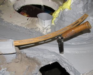
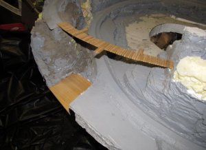
here is a photo of the test fit. it moved some as the photo was taken, the impromptu center support wasn't level. The bridge deck fits pretty well ( some times on a tight curve, they relax a little as they are unpined and pulled of the wax paper, and the radius increased.) This one staid pretty close to where I wanted it , and I have a real good fir after trimming the roadbed a little .


where I am using flex track I will remove the ties from the middle of a section of flex track, and spike the bare rails to the bridge deck , and that will leave a section of flex on either side of the bridge , which will give me a smooth transition onto and off of the bridge. when there are rail joints right next to a bridge, you get an increased chance of a kink, or a vertical curve, things you don't want any where near a bridge.


As I had stated, I'm going to go with an over sized bridge tie. bridge ties end up hanging out there, and a lot of the scale size bridge ties I have used in the past end up damaged, especially the long ones that stick out to form refugees (A wide space that gives anyone stuck on the bridge when the train comes a place to stand out of the way.) Refugees are required by law, and the maximum distance from each other is set by law as well. I don't know the numbers, I use more of them closer together than likely on a prototype, but I figure my RR's people are likely to be slow in more than one way.


I have picked the size for my oversize bridge ties, which just happened to be a size I had pre cut in the red cedar I used for the stringers. way oversized even for a standard gauge tie, but these being on a portable will be in harms way more than usual, so I'm going to err on the side of stoutness this time.

now I have to figure out just how long the standard bridge ties will be and how long the refugee ties will be. I had a jig made for the Sander's Gorge bridge , which I will use if I can find it.
 
Last edited:

Bill Nelson

Well-Known Member
Dec 14, 2008
2,680
467
78
Clarksville Tn
SMLA-1 brdg t jig .jpg SMLS-1 br t-2.jpg SMLA-1 brdg dk 2-1.jpg SMLA-! brdg dk 2-2.jpg SMLA-1 brdg DK 2-3.jpg Bridge deck progress

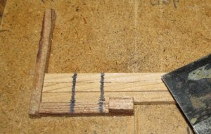
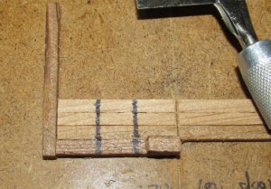
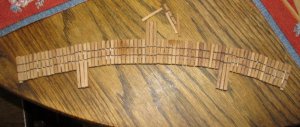
After I determined what size lumber I was going to use for the massively oversize bridge ties, I got a small scrap of masonite, and made a little jig to help me cut the ties to a uniform length. I Put little marks on the jig, showing where the rail placement goes.. this helps me get the ties centered on the stringers, which are directly under the rail location. I also mark the rail position on ties when I am handlayiong track off of a bridge as well, usually I use pencil, this time I used a very thin marker. The lines on the ties help me get the ties ligned up, and gives me a guide when putting down the fist rail, which helps me keep the rails centered on the ties. This batch of wood has some variations in the size, so I will sand the bridge deck down to get if as flat as possible before spiking the track. that will remove a lot of the marks, but that won't be a problem, as the rails will follow the stringers, so I can use the stringer as a guide when spiking the rail.


in the photo you can see I have added a block of wood at the end of the jig where I saw off the ties. this keeps the saw off the jig. When I don't do that I end up getting sloppy a cutting very small pieces off the end of the jig, creating shorter and shorter ties.

I had another jig on the same board to make the longer ties for the refugees. with scale ties, four ties will make a good refugee, but with these massively overscale ties, three looked better.

I glued the ties down with tackey glue (like traditional white glue, but thicker) taking care to get the lines marking rail position directly over the center of the stringers.


I just need to sand on the top of the deck to level it out. fortuanately I am using aromatic cedar, cut from a plank I bought @ Kroger's, that was intended to smoke a salmon on it. the Cedar has nice color, and so I can use it without staining. Had I used my normal stained yellow poplar, I'd have to go back and touch up the cut ends of the ties, and anywhere I had to sand.


Bill Nelson
 
Last edited:

Bill Nelson

Well-Known Member
Dec 14, 2008
2,680
467
78
Clarksville Tn
SMLA-A  Tst#2.jpg SMLA-1-A.j  rok  ext 1.jpg SMLA-1-A.j  rok  ext2.jpg Time for more scenery work.

Ok,


I'm sure you are thinking, "But you are working fast and furious on the bridge deck.


Well let me introduce you to another of my bridge rules. The first was the bridge deck deserves a lot of attention, as it it isn't right, your bridge won't look realistic.


Rule number two comes from years of painful experience. it is Do basic scenery under and around the bridge before the bridge goes in place.


If you don't follow this rule then one of two, and possibly both things will happen. You may end up doing a substandard scenery job under the bridge for fear of getting plaster glue, paint, and whatnot (Watch out for the whatnot, that stuff is a mess) all over your bridge. Also if you are making a trestle, the bents need to make it to the ground. If you have the scenery in you can plan for foundations for the trestle bents, and make them just the right size to fit perfectly between the installed bridge deck and the existing scenery. it is much easier to build the bridge to fit the scene than the other way around.


A bridge will automatically make a focal point for a scene. Viewers eyes will be drawn to the space around the bridge. In this case this bridge will probably be the focal point for the whole small layout . The eye will be drawn to the bridge, and what is around it is going to get seen, so you want to make that area look good.


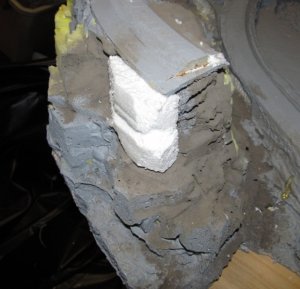
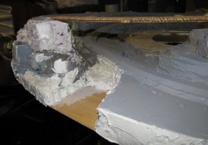
I really like the side of the bridge that has the rock pillars sticking up, but the other side looked a little skinny, so I cut a block of Styrofoam up to buff up the bluff. I carved the chunk of foam , and then I slathered it with the acrylic spaclking compound, like motor on a brick, and smushed it in palace.

Then I filled in the nooks and crannies on that point with the spaclking compound. when it dries I can carve it and knock off any thing I don't like, and I will be ready to paint it.

I also spliced in some thin plywood at the bottom of the creek, where I cut out too much foam. I notched the bottom side of the foam to let a little square of thin plywood in place, and glued the plywood in place with Gorilla glue , and slapped some Gorilla tape on to keep it in place while the glue dried.
 
Last edited:
Z

Zathros

I lived within 20 feet of a train track for 24 years, I really appreciate the way you captured the irregular shapes without going over the top, in your railroad ties. I moved out 12 years ago after I purchased a home. The station was about 150 feet from where I lived. I saw this ever single day for 23 years!! 100 years ago, there was a turntable there, which branched off into Ridgefield, hence, Branchville train station. :)
 

Attachments

  • Branchville Station.jpg
    Branchville Station.jpg
    124.7 KB · Views: 22

Bill Nelson

Well-Known Member
Dec 14, 2008
2,680
467
78
Clarksville Tn
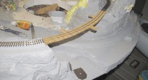
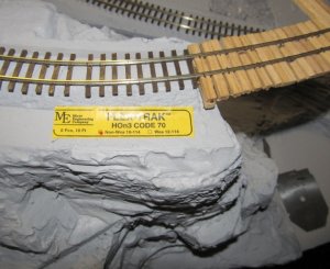
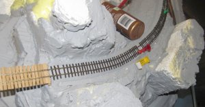
SMLA_!bgtstle lp br 1.jpg SMLA_1bgtstl lp 2a.jpg SMLA_1bgtstl lp 3a.jpg SMLA_1bgtstl lp 4a.jpg The track has started going down. the Micro enginerreing code 70 hon3 flex has scale size spike detail. this makes it somewhat fragile. the track is a little stiff, and doesn't like going as tight as a 16 inch radius. I tried spiking it down, and it wasn't going down as smooth as I wanted it, so I backed up, and am gluing the track down with tacky glue, and where it is being ornery I am forcing it to the curve I want with plastic thumb tacks.


a lot of tacks are used at the joints of the flex track pieces trying to avoid any kinks, as any kink in a 16 inch radius curve is likely to cause problems.


The track is about half way done. On the other side I will have a passing sidding, so I will have two micro engineering #5 switches to install with ground throws; that shouldn't be any more complicated than doing the bridge deck. Once the track is all in I will work to wire it up, and I will also work to design and build the trestle bents, or whatever I'll use to hold up the bridge.


Nelson
 
Last edited:

Bill Nelson

Well-Known Member
Dec 14, 2008
2,680
467
78
Clarksville Tn
ASM-bgtstle  w  tk 1.jpg ASM-bgtstle  w  tk2.jpg ASM-bgtstle  w  tk3.jpg More track

In spite of having to pay bills this morning, and do some work related to an out of state property sale, I got time to do some track work on the loop.


I am up to the switch on one side, and have some work done on the piece of flex track that runs into the switch on the other side. about fifteen minutes more work will have me ready rio hook up the NCE DCC system to it with jumper cables and do some testing with the Blackstone C-19, to be sure it is happy with the existing track before I proceed.


If the C-19 likes it as it is, I will wire in the switches with DPDT switches ans ground throws, and wire up the layout with four main power leads two near the switches on the outside loop, and two nearby on the inside loop. I will make provisions for more power leads in case they are needed later.

I will probably set it up so it can be run off of my small NCE DCC systen, or DC, but I'm not sure how simple or sohisticated that will be. I might just have some wires sticking out some where that I can hook some small alligator clips on to.


Bill Nelson
 
Last edited:

Bill Nelson

Well-Known Member
Dec 14, 2008
2,680
467
78
Clarksville Tn
ASM-bgtstle  w  tk5.jpg what fun!!!!

Yesterday I got a little done in spite of having to do my bill paying and some realestate paper work done.


Today I got a hair cut, picked up some medicine from the pharmacy and checked out a deeply discounted a canoe, that I'll buy if certain upgrade parts are available.


This didn't leave me much time to work on the Bugtustle loop, but I got one more piece of flex track in place. My work week is over tomorrow morning at 6:00 am then I can start wiring up the switches and the ground throws. I may wire up the whole tiny railroad at the same time. Trains will be running soon, and I'll work on the trestle bent design, making mock ups out of foam core. the foam core mock ups will support the bridge deck for early play, and I can pull them out one by one to use them as templates to build trestle bents that will fit the scenery perfectly.


the next installment will either cover the trestle bent design techniques, ot the way I wire these fine Micro engineering #5 switches. ( which are a big improvement over the Shinohara #4 switches) and the way I use DPDT switches as ground throws, and to control frog polarity,


Bill Nelson
 
Last edited:

Doctor G

Well-Known Member
Sep 1, 2008
1,415
298
78
Clarksville, Tennessee
Very Fast

This layout is coming together very nicely and very quickly. Always enjoy your bridge work and your philosophy on model bridge building.

Looks like there is an interesting siding developing on the upper loop. What business will the RR serve there???

Tom
 

Bill Nelson

Well-Known Member
Dec 14, 2008
2,680
467
78
Clarksville Tn
just a passing siding

Tom,


Just a little passing siding , will probably have a small station and a water tank. perhaps a couple buildings. I don't think there is going to br too much to Bugtustle NC.

Bill
 

Bill Nelson

Well-Known Member
Dec 14, 2008
2,680
467
78
Clarksville Tn
ASL-swtch  btm #1.jpg ASL-swtch  btm #2.jpg wiring the switches part 1

I have started the work wiring the switches.


I am using two of the very fine Micro engineering #5 switches. for years the Shinoharra #4 was what was available; but the micro engineering offering looks beter, and the genteler divergence is much appreciated by many locomotives


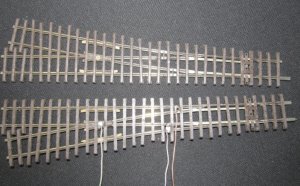
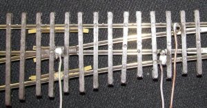
These new switches are designed with DCC in mind. the point rails are isolated from each other. each is tied to it's respective stock rail electrically, and the frog is isolated from everything. a little stud from the frog casting sticks out of the bottom of the ties, so it is easy to solder a wire to the frog without it showing.

Like wise, I solder wires to the jumper wire between each point tail and stock rail on the underside providing each switch with three wires, on for each of the outside rail, and a frog wire, which will run to a DPDT switch which will both serve as a ground throw for the switch, and power the frog appropriately . after I solder the wires on I check thith an ohm meter to be sure I havent unsoldered the little wire that conects the stock rail to the point rail on each side. it is a paint to discover that you have done so after the switch has been installed, and you have to either remove the switch to repair it, or make a new jumper wire that will be visible.


The leads to the outside rails will also provide two of the four power leads this railroad is going to get, so once these switches are wired in, I will have 2/3rd of the wiring done for the track on this project.

The wire I am using is some wire from a communications cable I scrounged some where. they are color coded, but it is real subtle. I traditionally use green for frog wires (because frogs are green, it is easy to remember. I'm using the violet wires for the outside rail, and the tan wires for the inside rail. the switches will provide an electrical fead for the outside loop an nearly opposite ends of the layout. I will add two feeds to the inside loop adjacent to the switches as well, so I will have four power feeds in a 4x4 layout. If I need more I can add them later. I have a really long skinny drill bit I have used to install phone lines in my 130 year old house. it will be able to drill through the plywood, and all the way through the foam. I will cut a trench in the bottom of the foam to run the wires around, and when I'm done underneath, I'll cover them up with duct tape so they don't snag on anythin


In my next installment I will wire up the DPDT switches. When I hook them up to the switches, and get them installed I will be able to hook up My NCE power cab with some jumper cables, and have an operational little railroad. I want to clean off my worktable, so I can set the layout on it. that is going to take more time and work than wiring the switches and DPDT ground throws up.
 
Last edited:

Doctor G

Well-Known Member
Sep 1, 2008
1,415
298
78
Clarksville, Tennessee
Good electrical workmanship. I used DPDT sliding switches on my Sugar Cane mini layout. I found I had to glue some wood pieces in to the foam to be able to secure the switches.

Tom
 

Bill Nelson

Well-Known Member
Dec 14, 2008
2,680
467
78
Clarksville Tn
When I started this, I have 1/8th inch plywood cut out as a cookie cutter roadbed under the track every where but at the big bridge. at the switches the plywood extends out enough to hold the ground throws.


this may have doubled the weight of the layout, but I like having the track on something solid, and that is a challenge when the layout is 80% foam.

Nelson
 

Bill Nelson

Well-Known Member
Dec 14, 2008
2,680
467
78
Clarksville Tn
ASM grnd thrw #1.jpg ground throws

I have two ground throws wired up. My local radio shack has not been carrying the little DPDT switches I have used for 35 years, so I am using some SPDT switches from a local electronics store The trow on these smaller switches is a little too short to be ideal in HO, but works ok in HOn3.


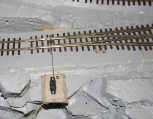
The center green wire goes to the frog. the other two wires go to the outside and inside rails. note I have some heatshrink over the frog wire's terminal, to lessen the chance of a short since the other two wires are not adjacent to each other the possibility of a short there is much more remote.

I have used a tiny drill to drill a hole throgh the switches slide handle, and I will fit a small phosphor bronze wire into that hole that will got to the switch, with a little z bent into it that will allow some springiness, and also allow siome adjustment If it isn't perfect the first time.


Bill
 
Last edited:

Bill Nelson

Well-Known Member
Dec 14, 2008
2,680
467
78
Clarksville Tn
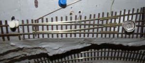
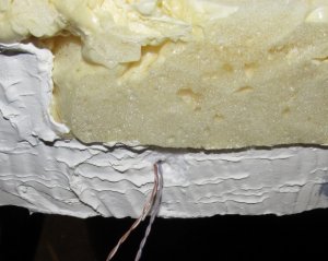
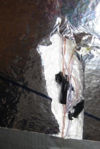
ASL bgtsle wring 2.jpg ASL bgtsle wring 3.jpg Last weekend I hooked up some wires to the layout. I had cut a trench in the bottom of the foam layout and put two wires , each made from two smaller phone wires that were twisted together and soldered at the ends so they would cary more current.

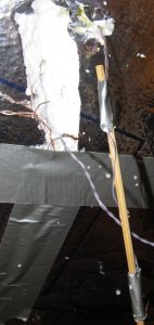
I extended the wires from the stock rails of the switches, and ran them through the foam. after some thought as to how to make that happen, I duct taped the wire to a bamboo skewer, made for shisk-kabobs, poked the skewer through the foam, and used a pair of vise grips to pull the skewer, and the trailing wire through the foam. I also stuck extensions of the two wires across the bottom of the layout through the side of the foam layout, and that gives me a place to hook up a power pack or my NCE power cab DCC system


I have also cut some square pads for the spdt switches, with a center cut out, and have them installed to the sub roadbed extensions left for that purpose next to the switches so I can hook up power and run a train.


sadly the inside circle is too steep for my Blackstone C-19 to pull a long combine up, but I can cut between the plywood and the foam and change the grade if I want to, the outside circle is,t that steep, so that locomotive is ok going counter clock wise around the layout.
 
Last edited:

Bill Nelson

Well-Known Member
Dec 14, 2008
2,680
467
78
Clarksville Tn
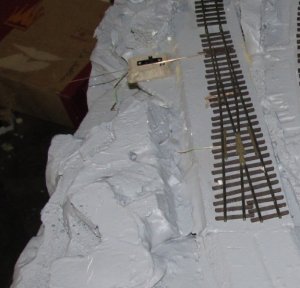
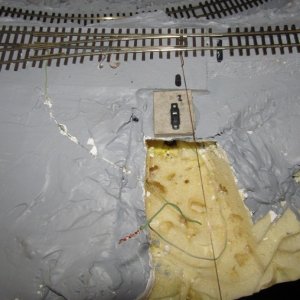
ASL Bgtstle pwr fd.jpg ASL BGtstle wrng det.jpg ASL Bgtstle  sw  stp #2.jpg ASL Bgtstle  sw  stp #1.jpg ASL skewer.jpg Here are some more photos

in one photo you can see where a chunk of scenery was cut out to get access to the switch wiring, that scenery came out in one piece, so I can plug it right back up to cover the wires.


I also included a photo of the skewer used to get wires through the foam. all the wires in the trench have been covered up with duct tape, so they won't hang put and get snagged on things when the layout is moved.


Next thing to do is to hook yo the phosphor bronze linkage from the ground throws to the SPDT switches, and add the track between the two switches ( with gaps in the rails off the frogs, so I won't have a dead short).


If I decide to alter the grade on the inside loop it should be relatively easy to cut the plywood off the foam, there is plenty clearance under the trestle, so If I wanted to I could raise the lowest level of the track some. whatever I do I can try propping up the track with foam wedges, and test it befor I gle stuff back in place and start to repair the scenery.
 
Last edited:

Bill Nelson

Well-Known Member
Dec 14, 2008
2,680
467
78
Clarksville Tn
ASL SWCH LNK BGTSTL.jpg ASL bgtstle LP crl 1.jpg more progress

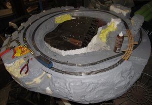
I have the switches hooked up, sadly I damaged the throw bar on one. I have attempted a repair, and that repair may need some modifications later. if that isn't satisfactory I may need to scratch build some points for the switch, or replace it entirely. But I got the circle enclosed, so I only have the outside passing track to put down, if the switch repair works.


earlier I had made a kraft paper template for the shape I wanted for the first part of the removable center scenery plug. So far this is just cut at 90 degree angles, but I will shape it considerably, I figure it will get another one or two rock spires like the ones to either side of the track on one side of the trestle.


this project is continuing to be fun. Once I have a train running in a circle, I may check to see what I can do to modify the grade on the inside circle so my C-19 can handle it with a passenger car. I'm thinking of putting a Tsunami Decoder in my Westside C-16, which weighs a lot more, and pulls stronger, then I could get double headed sound, and pull a sizable train
 
Last edited: