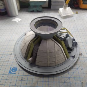
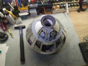
1/12 Apollo Command Module

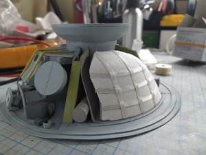
The first test to simulate fabric elements. The base is a fabric plaster from the pharmacy, and ribbons from sewing accessories.

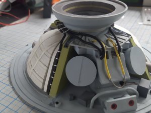
After assembly all parachutes II will also add an opening cable.

The remaining 2 parachutes, I will do it differently. I will print the mirror parts, I will glue the plaster on other side, and then assemble. Cutting the fabric in place is very difficult.

For the ribbons I used g-s hypo cement glue, only this glue was able to glue the fabric ribbons to the paper. (I had to quietly drag it away from my wife.) :laughrolling:
IMG_20210504_234728.jpg
 
I must concur, the fabrics add texture that printed paper cannot. The same as an armor modeler using glue soaked tissue to make the tarp covering of an armored vehicle.
 
Really superb work! :)
 
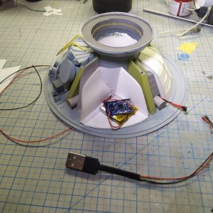
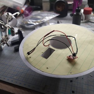
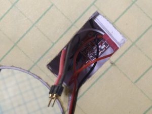
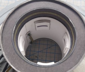
At this stage, main electronics are installed, the model will be powered by LiPo battery, with charger, and switched on with touch button. The touch button had to be modified since it cannot pass a large current through itself, I had to install a transistor key.

IMG_20210511_124737_797.jpg

IMG_20210511_124737_827.jpg
IMG_20210511_003448.jpg

Charger external port.
IMG_20210511_003640.jpg

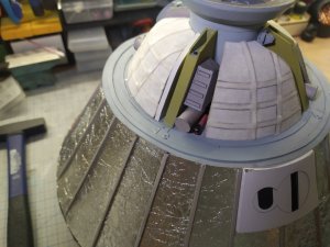
Just in case, I impregnated the fabric on parachutes with CA liquid glue. And now I need to figure out how to implement the cables and lines going from the parachutes to the mortars.

And implement a disclosure system. There was an attempt to do it out of paper, but since I started using fabric, it doesn't look good. I am trying to find a very narrow band.

Unfortunately I could not upload a video how touch button works.
IMG_20210511_124737_845.jpg

IMG_20210511_003700.jpg
 
Last edited:
:Bravo::Bravo::Bravo::Bravo:

The best thing is, that little circuit you installed has probably more power than the actual CM had! :Grin:
 
  • Like
Reactions: Kolokolnikov
Here is circuit diagram of my electrical addons for model

 
Adding a transistor to turn on larger current is always good practice. That's what they are for. ;)