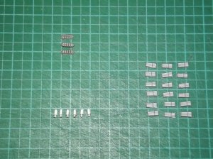
Those cannons look GREAT! I like how they turned out! Everything looks very straight forward!!!
Launch when ready!
- Thread starter Revell-Fan
- Start date
You are using an out of date browser. It may not display this or other websites correctly.
You should upgrade or use an alternative browser.
You should upgrade or use an alternative browser.
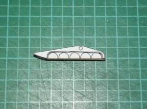
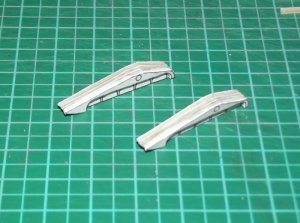
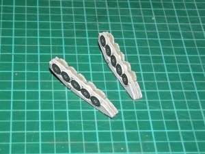
The landing gear is a challenging design. The original was made of many tubes which would be very difficult to make at this small scale. It was @Rhaven Blaack who came up with a simple but effective solution: 2D images of the gear are laminated to card and stacked on top of each other. This is idiot-proof!
The only problem was to determine the thickness of the layers. At first I laminated all parts in question to 1mm card:
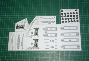
The aft LG:
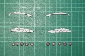
The front LG:
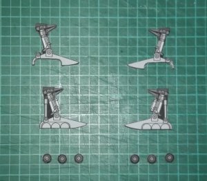
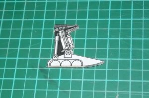
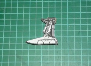
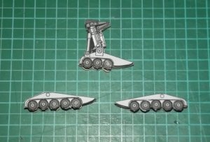
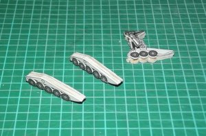
Sure, the paint is still missing. I have to see if I leave it this way or if it is better to use thinner card. However, the thinner the card the closer it gets to the original but the flimsier it gets. It has to hold up the whole plane. The larger ones will offer more possibilities and maybe give me other hints.
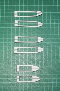
The skies were much too thick. I carefully pulled them off of the card and glued them back to back.
To be continued later when I'm back from work. CU!
Basic construction complete.
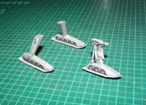
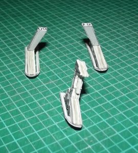
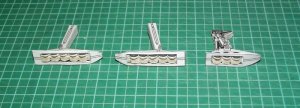
There will be a few additions like a splash shield, a rod at the aft of the rear landing gear and a funny "L" shape and - of course - extra pieces for laminations. I'll make them on-the-fly and will present them to you once they are available.
Careful observers may notice that the top half of the LG is thicker than on the original mockup. This was a compromise to ensure a stable connection. If I had produced a similar connection the center of the LG woud have been 0.5mm thick which would never be able to carry the whole plane. It would simply break off. However, since this construction has proven stable and easy to build I'll be carrying it forward to the bigger ones - with the same lamination thicknesses. So the larger the scale gets the more it will resemble the original. And most importantly: If you find a better way please post it here; if it works better I may revise the kit accordingly.
The next phase will cover the engine tubes. Fortunately they don't have any difficult parts.
Last edited:
Just a small sitrep:
Yesterday I had to recharge the accus of my camera, so I was unable to take as many pictures as I wanted. I assembled the high engine parts and noticed that an additional plate was necessary. I added it on-the-fly and revised the assembly of the intakes (a flap got in the way and was tranferred to another part). The greeblie tube right behind the intakes looked a bit too small. I have added another ring element to increase the diameter. I'm now checking out the effect. Basically I have all major components of the plane at the ready for the final installation.
I found a major flaw in the undercarriage of the plane. The bottom part was way too long which must have been caused by an accidental stretching on the page. I spent the whole afternoon to fix it. In addition, the rear end of the part seemed to be too wide. I checked the CG model and found out that this was a rounding error that occured when I was tweaking the blueprints to match the filming miniature. The shape of the stern of the ship differs on both models which gave me a deviation of 1mm on both sides. I already reduced the width of the bottom of the Y-piece but apparently that wasn't enough. I don't want to alter the shape too much at this point, so I added a small step to the bottom which will compensate for the deviation. I'm curious to see how it looks on the finished plane.
Next I refined the landing bay doors. The inside is still untextured. Each door has two panels which look to be separated from one another but which in fact aren't. In the first draft I forgot this fact and left the second panel closed; now both open up as they should do.
Last but not least I got a nifty idea for the engines. This idea is so fresh that even Chris doesn't know about it yet. :Grin:Again it will be exciting to see if it works. Stay tuned!
You have my curiosity peaked!!!
I am greatly looking forward to seeing the pictures!!!
I am greatly looking forward to seeing the pictures!!!
I just facepalmed big time. What I thought to be a rounding error was in fact a human error. My interpretation of the blueprints was wrong and I took a projected line for a panel line. That led to this:
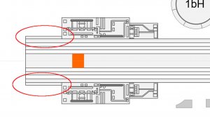
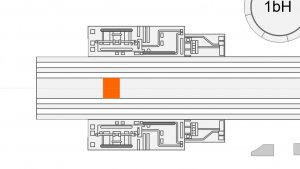
It should look like this:
And this is the projection that caused the error:
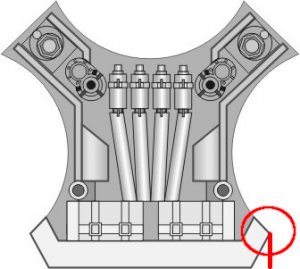
I'll have to move the edges of the Y-piece's bottom 1mm closer to the center to correct it. Chris will get the revised pattern, so be prepared to see a slightly different shape on the Beta test.

It should look like this:

And this is the projection that caused the error:

I'll have to move the edges of the Y-piece's bottom 1mm closer to the center to correct it. Chris will get the revised pattern, so be prepared to see a slightly different shape on the Beta test.
Alright, the rework is complete. I edited the vector data only, so the CG model still features the edge at the rear. It was not as difficult as I thought and to be honest, I'm glad that I noticed the mistake at this early stage. It would have been carried forward to the larger versions without being noticed and addessed. The last time such a mistake happened to me was when I designed the Landram turret (that one needs to be revised as well soon  ). I guess if you work on a project for too long you may overlook certain things. A hiatus clears your mind and opens it for new ideas. I'm sure I wouldn't have come up with the current design of the landing gear when I started the project. I'm now adding some lines to the LG bays as far as I can tell from looking at the scarce pics I have. The blueprints only describe the area to be smudged with grease and oil stains but don't show any panel lines. If everything fails I'll be using the Moebius Viper for inspiration.
The landing gear bays were totally empty which did not feel right. Thanks to RB I was able to make out some shapes despite the overall darkness of the picture he sent me. Much to my surprise the Moebius doesn't have ANYTHING at all in and on the bays so the kit was not helpful aside from giving me some creative license. So I made up a few additional lines and structures to make the bays look busy enough for a military vessel. This is the result:

I too revised the collar piece behind the intakes and turned it from a cylinder into a truncated cone. Again it was RB who encouraged me after I asked for his opinion. My plan was to use the cylinder on the small one and the cone on the larger ones; now the small one has them, too.
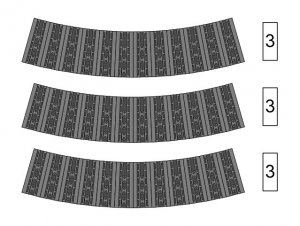
With these two things the final page was ready for printing - which led to an interesting comparison:
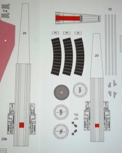
Even the untrained eye is able to see the difference between the old part 20 (left) and the new one (right). The previous one would fit a stretch limo version of the Viper. :Grin:

I too revised the collar piece behind the intakes and turned it from a cylinder into a truncated cone. Again it was RB who encouraged me after I asked for his opinion. My plan was to use the cylinder on the small one and the cone on the larger ones; now the small one has them, too.

With these two things the final page was ready for printing - which led to an interesting comparison:

Even the untrained eye is able to see the difference between the old part 20 (left) and the new one (right). The previous one would fit a stretch limo version of the Viper. :Grin:
The details of the landing gear bays looks better than what I had imagined. The engine collars look better better than what we were first hammering out. I am glad that you were able to fix part 20 as well.
I am looking forward to seeing the rest of the build.
I am looking forward to seeing the rest of the build.
Here are the pictures I was able to take before the accus gave up:
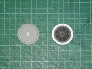
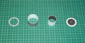
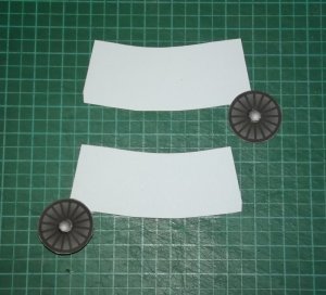
I was working on the jet intakes. There are textures on both sides meaning there are two parts which are glued back to back.
The fans receive a laminated center:
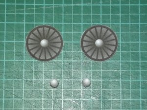
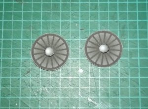
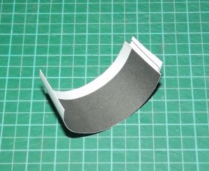
The high engine parts are pre-shaped before they are laminated:
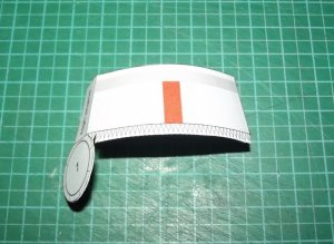
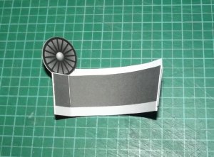
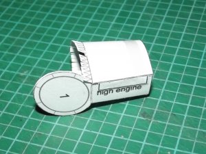
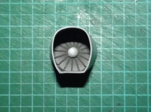
The side engines:
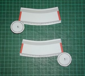

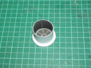
To close the back side the fan part has to be pushed inside a bit to allow the flaps to be folded the right way.
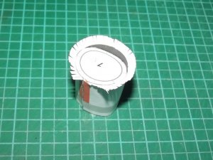
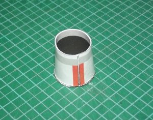
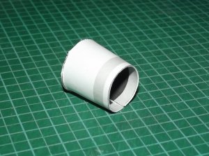
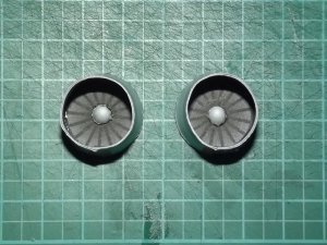
They still must be shaped correctly.
I was working on the jet intakes. There are textures on both sides meaning there are two parts which are glued back to back.
The fans receive a laminated center:


The high engine parts are pre-shaped before they are laminated:


The side engines:


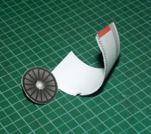
To close the back side the fan part has to be pushed inside a bit to allow the flaps to be folded the right way.


They still must be shaped correctly.
Last edited:
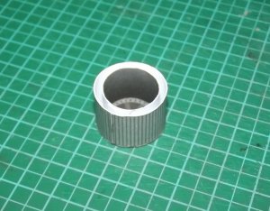
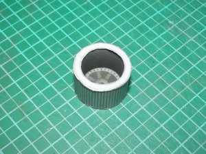
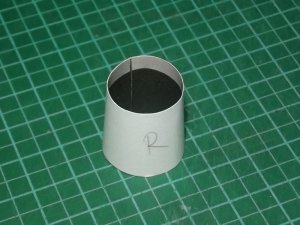
And something ... unspectacular: The engine tubes.
Well, they are ... tubes.
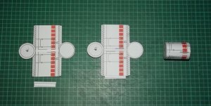
But tubes with incisions.
Before glueing together the part is unrolled and cut in at the black marks.

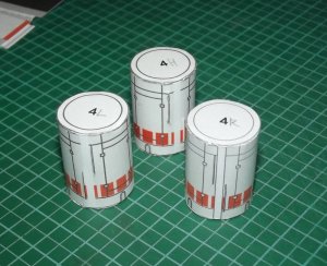
The incisions will hold the fin and the wings in place later. BTW, I took the idea from Ninjatoes' Mk II Viper. Thanks, pal!
Well, they are ... tubes.

But tubes with incisions.
Before glueing together the part is unrolled and cut in at the black marks.


The incisions will hold the fin and the wings in place later. BTW, I took the idea from Ninjatoes' Mk II Viper. Thanks, pal!
- Apr 5, 2013
- 13,876
- 10,216
- 228
I'm slowly transferring launch controls to probe craft..!


