Won't say what it is till later...ooops too late now!

Gandolf50

Researcher of obscure between war vehicles...
Staff member
Moderator


Got started on this as a break from doing a lot of strictly digital work, some smart builder out there will figure out what it is soon-enough, but for now I thought I would just concentrate on the build, without spoiling the surprise. After my last build one would figure ( even me) that I would pick something a bit easy for a break, perhaps even one of my own designs I have waiting that are calling to me, even now, nope! Here we go..
Engine block, fairly straightforward.

Engine-oilpan.jpg
and then the parts start getting smaller and smaller...etc etc etc
I will only do pics of stages along the build as this has WAY to many parts..as you can start to see, by the spark-plug ports!


started to run into instruction problems here as to how do things glue up, to the inside or out. I would prefer that things glue over the supports, but in this case all glue-ups are configured to glue to the inside edges, and all wraps glue, edge to edge, instead of over a support or corner, and since there are soooo many, will just have to live with it!

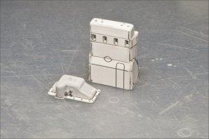
Engine block with head test fit, and a primer coat on it..
Engine-Right.jpg

Engine-Left.jpg
Plug ports more visible here, and yes there are spark-plugs 2.5mm x .43mm to be exact! Also you can begin to see what I have got myself into, those butterfly bolts are almost invisible when cutting, and they are good size compared to some !


Next have to get the exhaust manifold assembly..
Build Note: Cotton Swab with the paper core! works like a charm, dampen slightly and you can bend it, use a round plier, and if it starts to crush on the inside bend, flat plier the swab at a 90 to the bend and it will smooth it out again, use your burnisher to smooth things out a bit of sanding, a coat of acrylic varnish , tada!
and partially completed sitting on engine block for test fit!
Please Note...it is only 4.5mm tall!

and just to confuse those curious ones, and youngsters out there... here is part of the frame I built up while waiting for the engine to dry, and to get feeling back into my hands from working on the engine!
Fame-01.jpg

(BTW the axle is one of those paper sticks you get from make your own candy/sucker chocolate things, will try to find the name/brand for next time. They are 100mm long and 4mm diameter). They have a hole from being wrapped down the center, that fits a 1.3 mm wire perfectly! Aluminium Electric Fence wire is perfect fit!)
Till Next Time..
PS .. any specific questions on any part of the actual build, as always! JUST ASK!
 

Attachments

  • Engine-oilpan.jpg
    Engine-oilpan.jpg
    169.2 KB · Views: 0
Last edited:

Revell-Fan

Co-Administrator
Staff member
Administrator
Moderator
At first I thought it was the beginning of the motor which can be found on the side of the Millennium Falcon, but this is posted in "Armory & Military". So it could be a tank, a jeep or a Kübelwagen... :)
 

zathros

*****SENIOR ADMINISTRATOR*****
Staff member
Administrator
Moderator
Looks like the old tractor engine "CT3 XT3" from some very old tractors. I''m probably off. Nothing modern would have an exhaust manifold like that. ;)

XT3 CT3 engine.jpg

Tractor.jpg Tractor 2.jpg
 

Gandolf50

Researcher of obscure between war vehicles...
Staff member
Moderator
Looks like the old tractor engine "CT3 XT3" from some very old tractors. I''m probably off. Nothing modern would have an exhaust manifold like that. ;)
An armored battle tractor..! ;)

Hurrah !! You each win the internet for a day! Right now I am fighting with a distributor, that is approx 7mmx4mmx4mm and really has too many parts for the simple object it is..time to MODIFY!! and looking ahead looks like worse things are coming!
Distrib.jpg
:eek: TINY PARTS TINY PARTS!!!!! Not Modeling Clay!!! Card Stock! seriously!!
 
Last edited:

zathros

*****SENIOR ADMINISTRATOR*****
Staff member
Administrator
Moderator
Yeah, I noticed some of the stuff there may be a bit over thought. Must have been designed during the unbearable lightness of being. ;)
 

Gandolf50

Researcher of obscure between war vehicles...
Staff member
Moderator
Yeah, I noticed some of the stuff there may be a bit over thought. Must have been designed during the unbearable lightness of being. ;)

Ya think? The spark plugs are 2.5 mm x .4 mm and are made up of 7 parts!!! ( actually the parts are TOO SMALL TO PRINT!!) ackkk!
 
Last edited:

Gandolf50

Researcher of obscure between war vehicles...
Staff member
Moderator
Tutorial: Using a burnisher for making curved parts behave properly! "as I was going to get to this shortly anyway! Might as well add it now..."
A burnisher is simply a very smooth surface, either metal or wood, either curved or straight that is used traditionally in two of the arts, Printmaking and Jewelry. To burnish the edge of a printing plate or to burnish the edge of a bezel to hold in the stone. So basically, it is when you create a polish on metal using friction, and also move the metal to hold a stone. Since a burnisher has such a high polish on it it is perfect for Card Modeling!
If you have a small strip of card and you rub that from end to end with the burnisher it is going to CURL UP, towards you! So for an example...

On our current model I have 2 sections on the frame that curve 2 directions on the solid frame body!
Burnish-01.jpg
In this view you can see the two pieces. They have to curl R-L and top-Bottom ( I pre-cut everything.. and had to put / paint part of the frame before I could do this Tut)


The left section has to fit in this area... A slight curl is started to mark position and transitions just by pushing around with the ol fingers...
Burnish-02.jpg
The actual burnisher is the lower tool, the one above it will also work and is a cuticle do-dad for pushing around your cuticles!
Burnish-03.jpg
I start , with the burnisher to curl the part for the R-L curl... ( NOTE: this is on the back side! also..if you are NOT painting your model, you will want to use as little pressure as possible, as it will GLAZE the surface of the card stock , as you are basically crushing it! Lightly burnish it and slowly lift the edge in the direction you are curling , ( if you lift too much you will CREASE it and that's not what you want !) Practice on scrap first!! Till you can make it move however you want!

It now fits R-L...
Burnish-04.jpg
Burnishing from Bottom-Top...
Burnish-05.jpg
DONE!...Glue up the cuts and get the rest done! See next post...
 
Last edited:

Gandolf50

Researcher of obscure between war vehicles...
Staff member
Moderator
To Finish up...TUTORIAL :
I do not use TABS, but when I do ,,, I cut them from COPY PAPER, and apply from the back, as that will leave the least amount of thickness for glue-up.. if the back has to be seen..I DO NOT USE TABS! I use CV glue and burnishing and glue the edges of the card.

For an example...
Small relief cut on side that has to end up centered on frame and glued.. Not much room in .24mm
Tabs-1.jpg
sliver of copy paper glued to one side of relief cut and allowed to dry.
Tabs-2.jpg
edges of relief cut and copy paper all glued up into one part...
Tabs-3.jpg
back side... enough room to still glue to frame and hold relief cut together and not interfere when piece is burnished into final shape, which in this area make an almost 90 degree curve!
Tabs-4.jpg
Back to Building...the rest...( re-building generator and distributor!! ) looked like lumps of CLAY!
 
Last edited:

Gandolf50

Researcher of obscure between war vehicles...
Staff member
Moderator
Small progress, I guess PUN intended..
Start off with the generator and distributor,, which I rebuild , as the first looked really bad with primer on them, ( hopefully these will look better) !
Alter-Gener.jpg
( those are 1/4 inch dots , by the way! ) These were a REAL PAIN to build, Kept dropping things even with various tweasers, third-hands and the like.. 3 sets of magnifying glasses on, (eyes are not what they used to be) hands are worse...! THEY are SMALL!!

For a break? I switch to some paint every now and then, so added some weathering to the exhaust and built the main coolant line to the radiator..which still needs finishing touches..( actually everything will need finishing touches once it is finally assembled )!!

Exah-Water.jpg

Then it was off to more tiny parts ..to prepare for even smaller parts to come...!! this time it is the main pulley system for the fan assembly...
Fan-Crank-Pully.jpg
NOTE! the bent rod next to the fan which is part 12 in the model..is actually the ENGINE CRANK for hand starting, why it was in this section I don't know, should have been later in the assembly, also DO NOT put it together as to see here!!! as it will not fit through the hole in the solid frame where it is supposed to go.. you either have to separate the assembly and glue up after the frame is completed to the inside and outside of the frame.. or enlarge the hole so that the end will fit through to the engine lower pulley..

Also took some time out to add a bit of weathering to the engine block as I will soon have to start gluing stuff to it!...

Front and Back views..

Till Next Time..

BTW.. Happy New YEAR!!
 
Last edited:

Gandolf50

Researcher of obscure between war vehicles...
Staff member
Moderator
Looks like the old tractor engine "CT3 XT3" from some very old tractors. I''m probably off. Nothing modern would have an exhaust manifold like that. ;)


...and the pix for the inspiration to go ahead and tackle this build!!
shtz-15_31.jpg
stz-htz_65-31_Baydeww2.jpg
;) Now the debate will be this... after all the work that will have to be done putting the wheels together..do I have the heart to smear mud all over them to display in a diorama as it should be?
 
Last edited:

zathros

*****SENIOR ADMINISTRATOR*****
Staff member
Administrator
Moderator
You could always make the mud removable, or make a diorama of someone washing it down. Superb thread, by the way! :)
 

Gandolf50

Researcher of obscure between war vehicles...
Staff member
Moderator
Well while others were nursing their hangovers from New-Years, I had one of my own..re-building a carburetor..and no.. not that type..mine is 10mm tall! Plans were of little to no help at all! Lucky was able to figure out what I needed from the Alfa-Builder and will work up a section for others to help them through this section! Actually will comment on my own original post and add in ALL the mistakes-workarounds and list of dos and don't as I run across them... figure it is better up in the front than buried here and there!
This is the Russian version of the carb.. and what I ended up with.. it is about 50% greebles.. and not complete, still needs fule lines and the like.. but had to stop to get the solid body/frame and the engine in place..so I could build the rest IN PLACE!!
Carb.jpg
Feel like taking my lighter seeing this to burn off the fuzz!! but after the bronze paint job will have to see!

I refer back to the burnish tutorial now.. and another reason I like using the process..had to work up front end that has a hull -like curved center bottom to the side rail, and an intersecting curve that is opposite..burnish!! baby burnish!! The designer and the alfa builder spent a long time and ended up changing all this in the second version but since I had most of it done beforehand...I went with the original version, and by burnishing, I did not need to use the remodeled pieces of the body or frame..though I did have to make new copies of one section as ( probably due to different card stock/builder error ) as they were short 1/16th .. but I test fit and burnished ..and picked one line to keep as a reference for both sides..and went for it ( figure why not..I can always..scrap it and build the updated version!) NO NEED.. the problems they had I did not! everything fit perfectly! ( once I added the 1/16th )...
Side-Skin.jpg

Front-Nose.jpg

Skin-04.jpg

Skin-05.jpg

Skin-03.jpg

Skin-02.jpg

Now you can see the double curve section, this piece wraps all the way round to the keel ( so to speak) which is something cardstock, don't always like to do! You can also see the reason for the ship references...looks like a hot-rodders landing craft!! Just need to stick a prop on this end and I'd be done!!

And a side view of the same..the curved pieces we made in the tutorial? Not on yet..but they fit NICE!!
And the engine fits JUST like it is supposed to!! Let's hope everything else works from here on!! as there is a second layer of "skin" to go over this first one, to add thickness and sturdiness, but mostly thickness as the original was solid cast!
хтз 1939_1.jpg


and the SECRET to building a great model...little tiny men with tools!!

стз 1934.jpg


Till Next Time!
 
Last edited:

Gandolf50

Researcher of obscure between war vehicles...
Staff member
Moderator
Thanks for the comments... it is appreciated! And for any will to tackle this tiny beasty along with me, here is a work upon the parts for the carburetor...
Original...Instructions...
Carb.png

The complete assembly with the fuel lines etc.

020.jpg

Should help to figure out this beast...
3d image courtesy of the designer, V. Melnikov of MBA Models

A quick note on the solid body construction... it did not go as well as planned... I don't know what they did with the second skin design, but it and the original is WAY off! at least the way I put the first layer of skin on, which should not have mattered in the least.. but in the original and updated the lower opening for the engine oil pan changes shape considerably in both versions.. and it should be just a slightly larger copy of the first layer so I had to redraw a new layer using a copy of the first one and stretch it out a bit... I saw what the Alfa Tester went through to get his build, but then he used model filler and worked everything in that fashion... but the way I used things everyone should be able to use the model as is, and not have to "Bondo" the thing! I see no sense in scanning the piece as it is simple to make from the original, so anyone that needs it I will show you how I did it, here shortly, need to figure out how to photograph the steps and hold the pieces on at the same time!
 
Last edited:
Top