

Salute your patience dude.... AMAZING... such a neat model.... I would love to see it in real, this is what i call i sperfection... couldn't find a single flaw man..... Way to go.... bravo....
Sd.Kfz. 9 Famo (Angraf 5/2005)
- Thread starter snake7
- Start date
You are using an out of date browser. It may not display this or other websites correctly.
You should upgrade or use an alternative browser.
You should upgrade or use an alternative browser.
- Status
- Not open for further replies.
thank you Elliot and atamjeet!
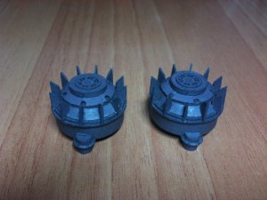
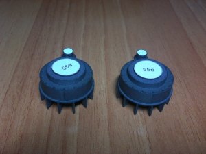
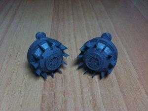
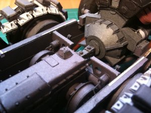
finished the base part of driving track wheel
you must be very careful with gluing part 56f to 55o. it must be on the same line, so later the wheel itself will seat exactly
sorry for the bluish color - night shoot
bugs:
part 56i - only 6 in count instead of 12 - printed the rest 6 from a scan
part 56c a little big in diameter - fixed it, but had minor problems latter with adjusting parts 56f
Attachments
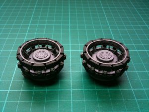
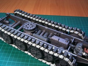
drive track wheels are finished
the assembling was not fun, because of a lot of mismatching
another thing: i glued the inner ring with pads not right and the instructions didn't get any clue. it supposed to be glued more inside the base part, but eventually it turned right, because my mistake put the wheel in same line as others and tracks laid on it perfectly
another surprise from the Famo
also the rollers must be placed a little bit left from the middle of pad and not on the left edge of the pad as it shows in schemes
bugs:
nothing special, but as i mentioned, a lot must be fixed to fit properly, because of mismatching
Attachments

pictures continue from previous post
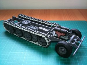
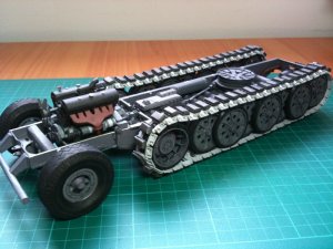
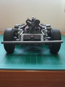
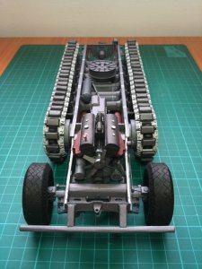
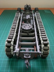
and after fixing the tracks i can announce, with joy, that i got to the middle of the project (challenge)!
the monster on its legs and i can continue to its upper parts
and after fixing the tracks i can announce, with joy, that i got to the middle of the project (challenge)!
the monster on its legs and i can continue to its upper parts
Attachments
")
thanks
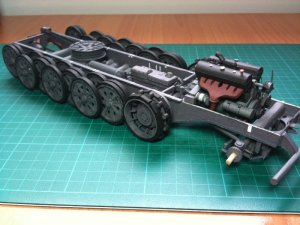
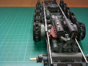
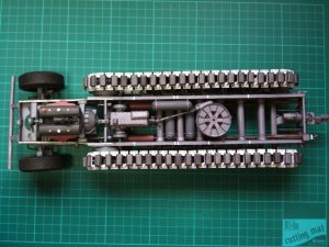
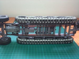
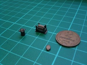
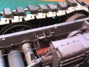
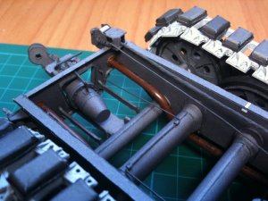
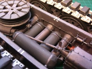
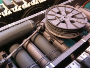
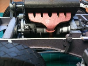
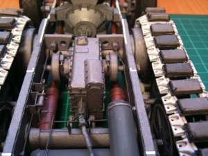
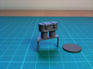
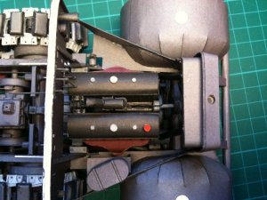
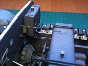
glued pneumatic cylinder and filter
and assembled all the pneumatics on board
this one in charge of pneumatic brakes to both drive track wheels and one tube goes to the back to output the air pressure to trailer, if attached
pneumatics connect from compressor on engine to cylinder and 3 compressed air reservoirs. from the cylinder tubes go to the brakes and to the back
even if this was very difficult to assemble, its the only stage when the mounting is possible
i felt like a jeweler for few days
bugs:
none
Attachments
 I am just in awe at your skill and ability to keep at it. Nice work and as always I look for more:thumb:. RGH
 thanks barry
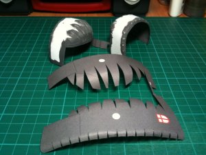
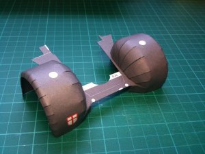
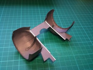
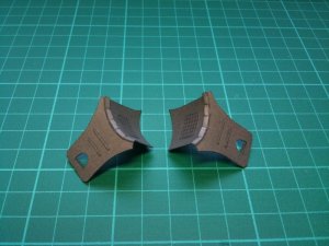
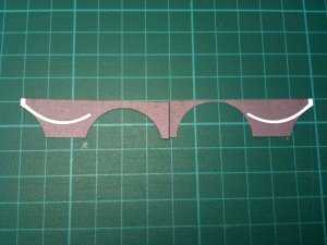
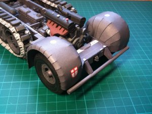
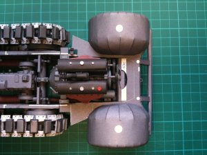
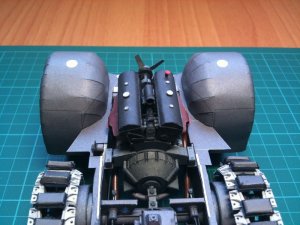
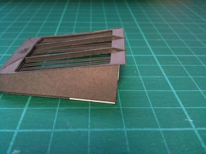
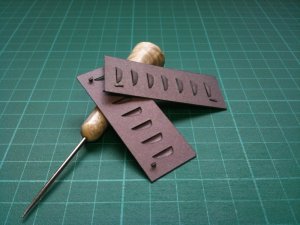
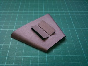
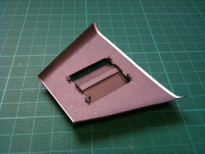
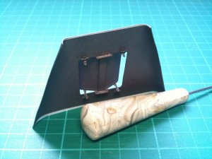
i assembled mudguards. it was tricky.
also glued middle step guarad, that i will put later, when rear mud guard will be in place.
i was very careful with mudguards and compared a lot the placement and other parts. the mudguards must be glued to the floor from rear to front at the curve of the floor
in this case the buldge is not to big and even if i still was in need to cut the side wall it will be possible to glue this two parts together, without cutting the mudguard.
there is a picture that compares modified side wall on right and not modified on left
bugs:
parts 61l, 61m must be in mirror, but they don't. also the arc strip is too small for the arc in the side wall 61e (a dropped the arc strip and glued only the step)
Attachments
Hello to all
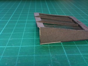
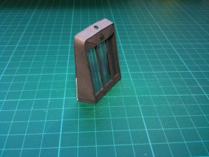
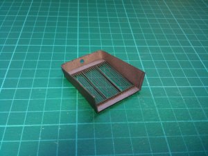
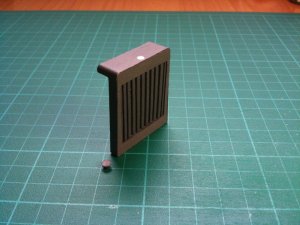
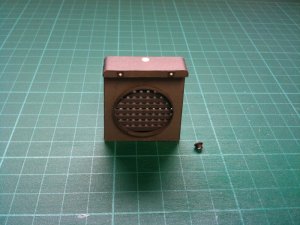
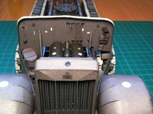
assembled radiator grill. and here also pops up design mistake, from nowhere!
the strip that surrounds the grill is too small, and the funny thing on each side its different, if you take the center as radiator cup (first 2 pictures)
it is computer design isn't it? i rest my case...
also assembled the radiator itself. there was also mistake in strip length, but small.
the details will be glued on the frame later. i still want to assemble some other parts and take measurements here and there
bugs:
parts 62d, 62e, 62f are too small - added a piece from reserve
part 63c is small on the endings - they will be closed by the supportings
Attachments


Hello
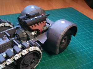
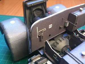
rear wall assembled
and i finally decided to put the parts on the model
it was hard one, but i managed to connect the side walls with mudguards
i was afraid that i will pass the upper line of the wall when i adjusted the curve to mudguard, but eventually it turned ok
also connected tubes from radiator to engine
the other tube, that goes from air filter to carburetor will be placed later, because i afraid it will prevent me to glue with comfort fuel system on rear wall
bugs:
detail 65h is short for few mm - i parted it in the middle. after i glue the engine cover above, it will not be seen
Attachments
Just wonderful, I have not looked @ for some time so I could see the amount of progress up to today. Fantastic workmanship and attention to detail. You thread will be of great add to anyone tackling this monster. Keep'em coming my friend. Rick
thanks guys!
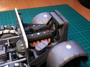
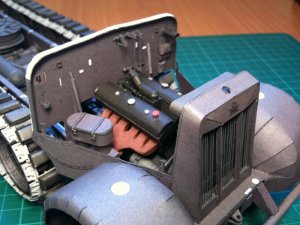
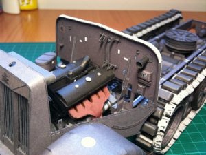
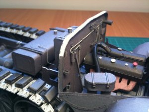
I've assembled engine side-covers and hood
the hood will be glued later, after i accomplish all the works in engine compartment
bugs:
part 65r - missing, ignored the part
part 66j - hinges to small, i glued the doors in place so no problems
part 66a, 66b - small in width for about 2 mm, will deal with it later, probably paint the white
the design of hood doors mechanism is wrong. there is no way to close the doors completely, i glued the doors in opened state
Attachments
Hi
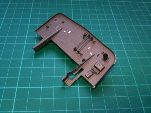
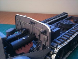
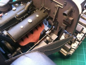
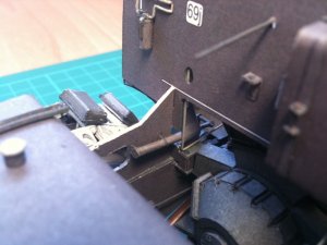
today i want to show you the finished fuel system
everything follows and connects logical
you can see it on the pictures
the tubes go from general tank, through reserve tank, through couple of filters and connect to fuel pump on the engine. from there it connects to carburetor, when form other side goes air filter tube
also i assembled forcer that connects to steering mechanism
bugs:
part 71j - to small for about 1.5 mm
part 71a - to small for about 1 mm
Attachments
- Status
- Not open for further replies.