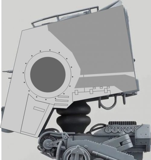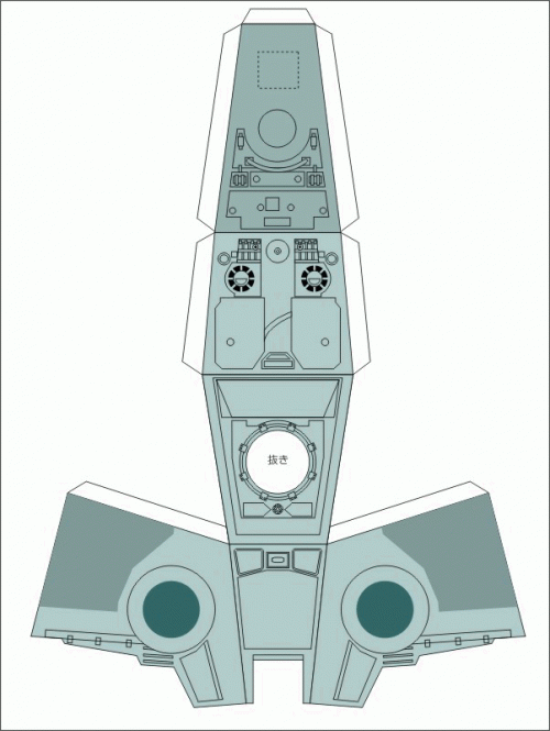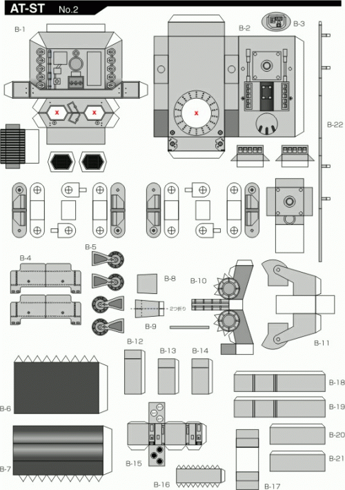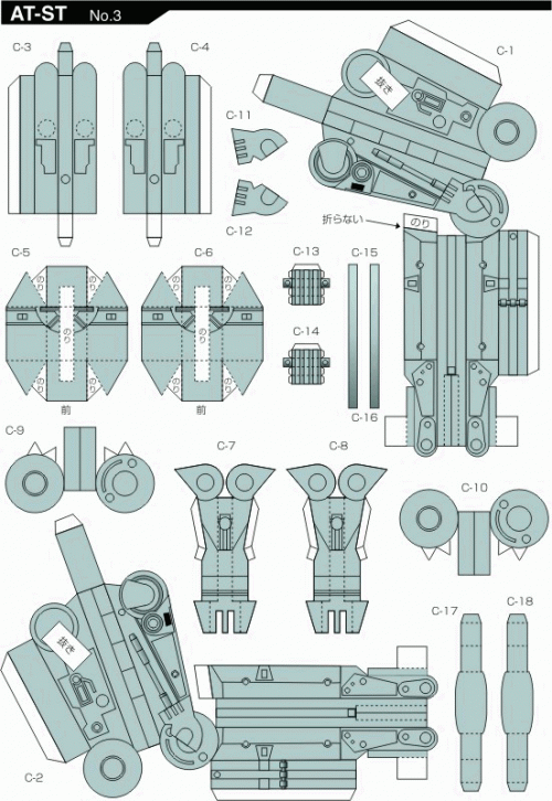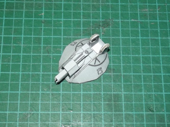




Pick your chicken (Imperial edition) ;-)

Revell-Fan

Co-Administrator
Staff member
Administrator
Moderator
Aug 1, 2009
11,609
12,349
228
Vreden
cp0.jpgcp1.jpgcp2.jpgcp3.jpgcp4.jpgcp5.jpg

Soon in theatres..!

:biggrin:


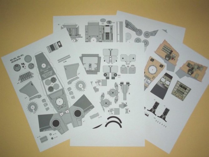
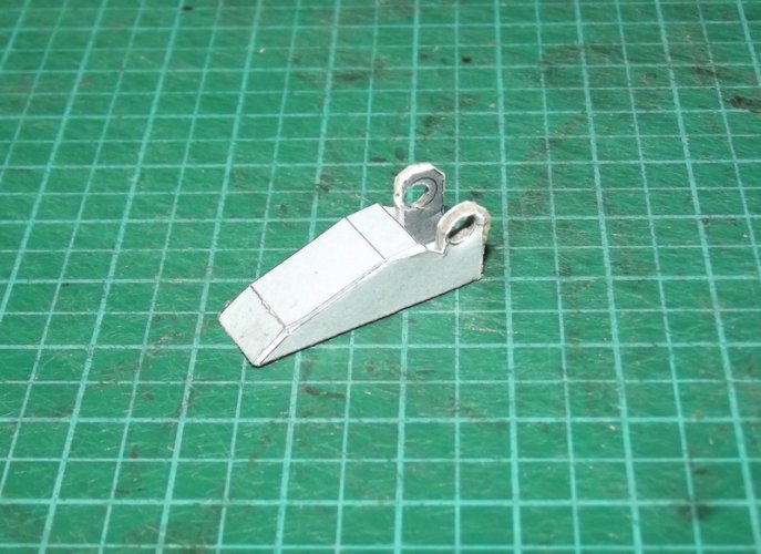
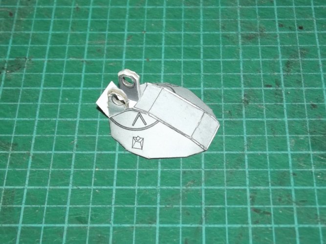
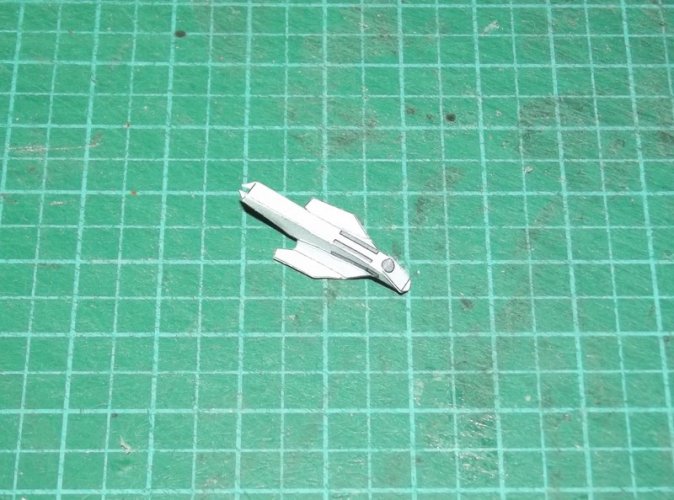
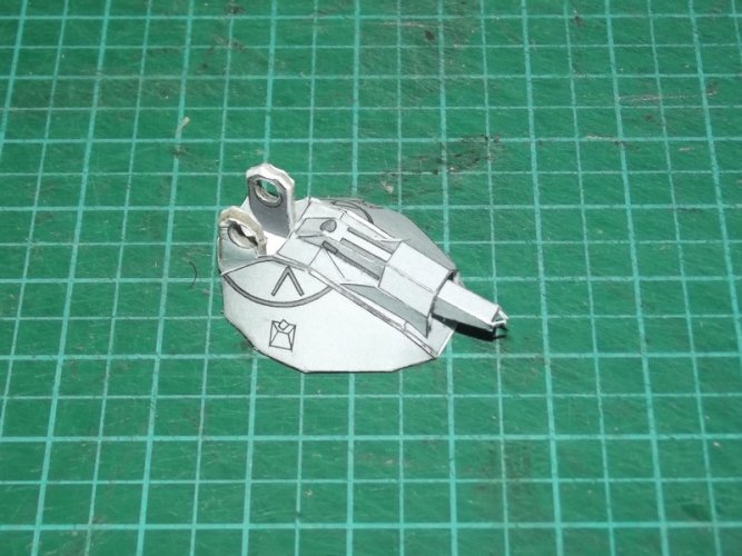
PHEW, but before we can enjoy this haunting masterpiece of thrill and suspense please allow me to introduce you to my latest project:


Building a better AT-ST from "Return of the Jedi".

:)

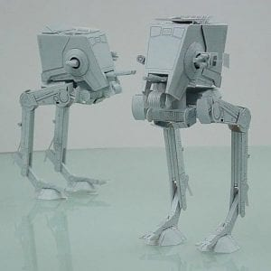
Christmas is coming and with it the need to pick a new subject for my Star Wars friend. My original plan was to make Shunichi Makino's A-Wing. However, I have no idea how to tackle the canopy glass. The experience with the Aston Martin showed that the most flexible sheet I have at hand would not be useful for that. So I postponed the idea till I have found a practicable solution. As a result a different model must be made. My choice fell on Shunichi's AT-ST:
1668463660174.png

It looks good, proportions are nice, the detail is crisp and is pretty easy to make. A few things must be changed of course, e. g. the view ports must be opened. That mod alone makes a HUGE difference.

However, when I studied the plans I found a few other things which might benefit from a small tweak. The feet stand out in a very strange way. I wanted to change that and started looking for other AT-ST models to see how other creators dealt with them.

Much to my surprise the AT-ST is pretty popular with papercrafters. There are several different versions by different creators in various sizes and with varying levels of detail.

Shunichi's model is one of the oldest ones available. It is 20 years old and unfortunately it shows. I would have liked to see him revisit this old war daggit but, ah well.

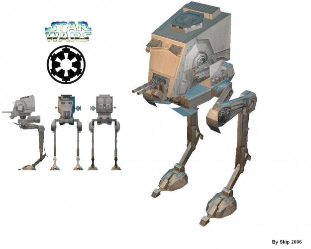
The next model was made by skip in 2006:
atstmain1.jpg

If you look closely you can see that the feet of this model look much nicer. This spawned the idea to combine the two to get a more authentic one. However, there are even more AT-STs out there.
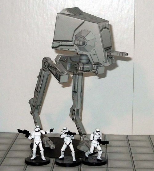
dakkodn-10257aa6-f808-4b11-9ad3-ff500b619794.jpg

This is a very nice model for gaming made by momirfarooq. The feet of this one are even nicer but other parts are fairly simplistic.

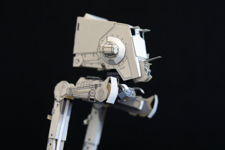
Two years ago yet another model was released:
f406cbc3.jpg

The details are quite nice but the model is very small and simplified.

And then there is the Bandai model which is basically a shrunken version of the filming miniature:
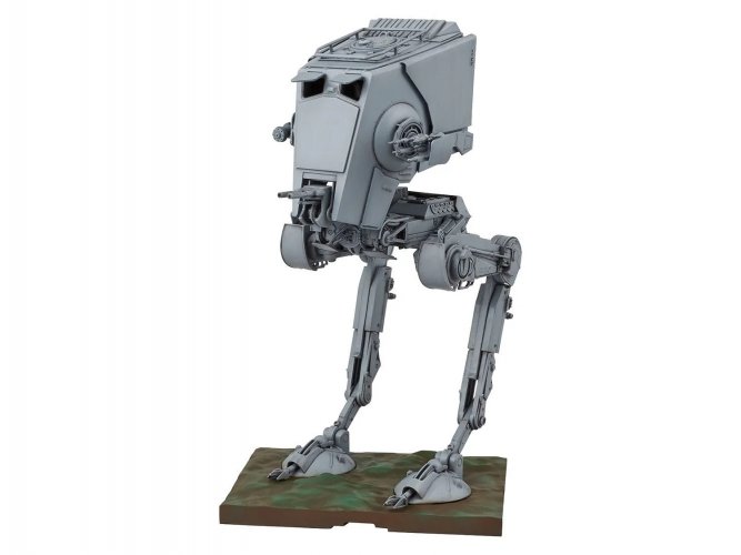
8287d6dc2320d821120846e27b3ffd45.jpg

This will be my reference model. :)


Basic conditions and goals


This project is one of four which I have determined to be concluded by Xmas. Number 2 is finishing the fire station to clear up my workspace. Number 3 is a special project to say "Thank you" and number 4 is supposed to be a gift for another friend. I know this sounds like a tremendous undertaking and by all means, it is. As a result I will not be working on any of the other projects before the year ends. That includes the official release of already finished projects like the G-80 derringer and the first part of the Colonial shuttle enhancement. To save time I won't switch between projects and focus on one topic till it is done. Then I'll tackle the next one.

There are five and a half weeks to go which means that I'll have to use any means necessary to speed up the design and build process. I have been working on the AT-ST for a week now which gave me the chance to develop a strategy to do it. I was able to successfully import Shunichi's kit in Corel and edit the parts. That was great because they gave me a canvas to work with. The parts look nice and it is easier to update them than to start from scratch. The majority of elements are already there, I do not have to build a CG model and create the texture which saves me A LOT of time.

Due to the short time frame I estimated one week for revisions before starting the actual build. This estimation was quite fine and I still have half a day left to tweak the neck and guns. So far so good. The goal is not to make the most authentic AT-ST paper model possible but to update and accurize perhaps the oldest model available and to give it a facelift of some sorts. So please don't expect a lamination party. And now, let's get into the chicken house and pick our favourite! ;)
 
Last edited:

Revell-Fan

Co-Administrator
Staff member
Administrator
Moderator
Aug 1, 2009
11,609
12,349
228
Vreden
Thank you! I really hope my plan works out. ;)

So I went ahead and imported the PDF into Corel. Everything opened just fine. :)

The first thing I did was to change the colour of all parts. The model comes with a blueish-greenish tint. I switched everything to 20% black (= light grey).

Some of you may certainly wonder why I did not use UHU02's model and simply build that one. The answer is simple: It is way too complex to make in the short time frame I have available. In addition, UHU's version is the AT-ST from "Empire Strikes Back". I am going for the "Return of the Jedi" version. Both models share the same characteristics but their proportions are completely different. I will however port over UHU's cockpit interior. This is well hidden inside the vehicle, so it won't matter much if it is distorted a bit. ;)

In order to see how the kit is assembled I took a look at various Youtube tutorials like this one:


Shunichi's model seems to be the go-to AT-ST paper model because there is a huge number of videos showing people assembling it. There are also various reports on different forums like kartonbau.de which helped me evaluate the kit. This report in particular showed me what some simple modifications can do:


The builder tweaked several parts and even made the model to come apart for easy storage! :)

This build revealed several of the model's original shortcomings. Something I would never have guessed and for a short moment I questioned my choice to have chosen Shunichi's model. However, it is the only model I know of that is already vectorised and can be tweaked in an elegant way. With growing doubts in my mind I swang into action.

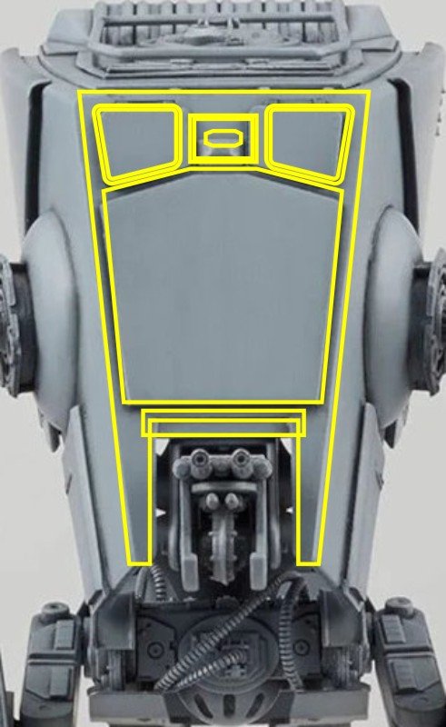
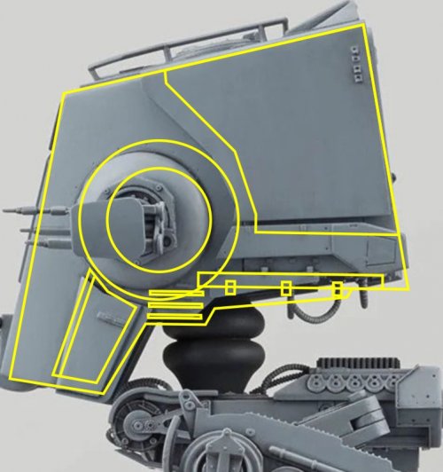
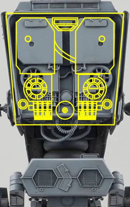
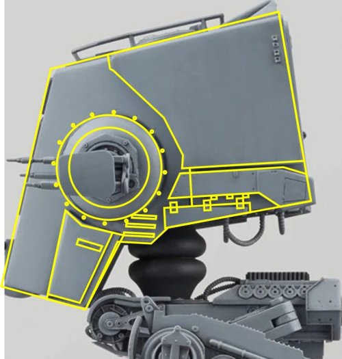
There are several great shots of the Bandai model all over the web. Among them are straight-on views of all sides. This proved invaluable because I was able to use them as a template to redraw the lines and refine the overall shape of the parts without having to build up a 3D model from scratch. And this is where it became blatantly obvious that Shunichi's model was not as perfect as I initially thought it to be!

1.JPG

The yellow lines show the unaltered template layed over a picture of the Bandai model. Whereas the front view does not look too bad

2.JPG

the side view and especially

3.JPG

the rear view show how off the proportions are.

A few hours later the template looked like this:

3a.JPG

With colour:

4.JPG

All changes at once:

5.gif


I was really shocked to see such a big difference. And this was just the beginning! :)
 
Last edited:

Revell-Fan

Co-Administrator
Staff member
Administrator
Moderator
Aug 1, 2009
11,609
12,349
228
Vreden
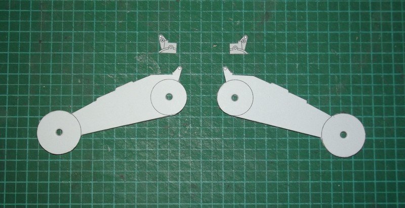
The kit features a strange configuration: The neck is attached at an angle. This makes the head look into the air or - if you adjust the tilt at the feet joints - makes the rear end go up. It is not possible to display the head and the engine box horizontally at the same time. This was changed by turning part B-7 into a straight tube. I also added two gradients to mimick the two cups which hold the head.

The engine block received a ton of new detail and I changed the assembly. The previous design did not close the box completely (there were holes which allowed you to look inside the body!). The new way should be much more intuitive and support a more finished look.

The lower armour plates B-4 are the same which are used on the rear of the AT-AT. I managed to copy them directly from Shunichi's kit. The wheels were separated from B-5 which will make the engine box look beefier.

The mouth gun was slimmed down to compensate for the revised head shape. The cheek guns are still a WIP.

Here are all changes in one image:

7.gif

The new rectangular parts in the middle are completely new hips. The old ones were extremely stylized and were designed for stability. The new ones were designed for accuracy.
 
Last edited:

Revell-Fan

Co-Administrator
Staff member
Administrator
Moderator
Aug 1, 2009
11,609
12,349
228
Vreden
The legs received the most significant change. The shape of all components was way off. The lower leg was longer than it should be and several detail pieces were added.

The assembly was changed and got much more intuitive and authentic. Each segment is laminated to 3.3mm card and connected via pins (made from toothpicks or wooden rods). You can already see where this is going: The legs are fully articulated now. I have freed the model from its frozen pose which will give you endless possibilities of posing it. I doubt that the model will stand on its own, so you will have to glue the joints together after posing, but the ability to pose it before will make it much more versatile and attractive for your displays and dioramas. :)

9.gif

The feet were borrowed from momirfarooq's AT-ST.

Time to sharpen the blades, guys! :)
 

Chuffy70

Well-Known Member
Jun 5, 2022
842
1,708
75
Norwich UK
The legs received the most significant change. The shape of all components was way off. The lower leg was longer than it should be and several detail pieces were added.

The assembly was changed and got much more intuitive and authentic. Each segment is laminated to 3.3mm card and connected via pins (made from toothpicks or wooden rods). You can already see where this is going: The legs are fully articulated now. I have freed the model from its frozen pose which will give you endless possibilities of posing it. I doubt that the model will stand on its own, so you will have to glue the joints together after posing, but the ability to pose it before will make it much more versatile and attractive for your displays and dioramas. :)

View attachment 208149

The feet were borrowed from momirfarooq's AT-ST.

Time to sharpen the blades, guys! :)

What a truly clever chicken you are!? stunning work
 
  • Haha
Reactions: Revell-Fan

spaceagent-9

Right Hand Man and Confidant
Moderator
Jul 10, 2013
3,107
3,473
143
62
pheonix
Looks like you did a great job mod'ing his kit!
I enjoy doing this kind of thing also, working out stuff that bugs me into something I am satisfied with.
However, I have found that it takes me a few builds to actually work out all the gaps and misalignments.
Your mods dont look like you have any failings tho. Keep Up the Good Work!
 
  • Like
Reactions: Revell-Fan

Revell-Fan

Co-Administrator
Staff member
Administrator
Moderator
Aug 1, 2009
11,609
12,349
228
Vreden
Thank you very much! :) The areas I'm most excited to know how they fit are the feet and the bottom of the head. I added a curve to the sides and made the front slimmer, so it will be interesting to see if it must be adjusted. This will be the first ROTJ AT-ST paper model with a curved head, BTW. I'm not worrying too much about the interior since you won't be able to see much of it later. The biggest advantage of the model is its box-like structure, something I haven't really noticed before. So far it's a really fun project. :)
 

Revell-Fan

Co-Administrator
Staff member
Administrator
Moderator
Aug 1, 2009
11,609
12,349
228
Vreden
And so it begins..! :)

DSCF1718.jpg

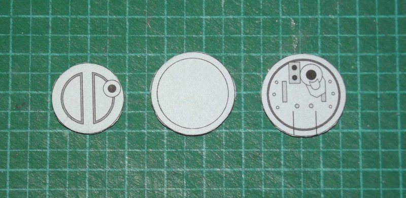
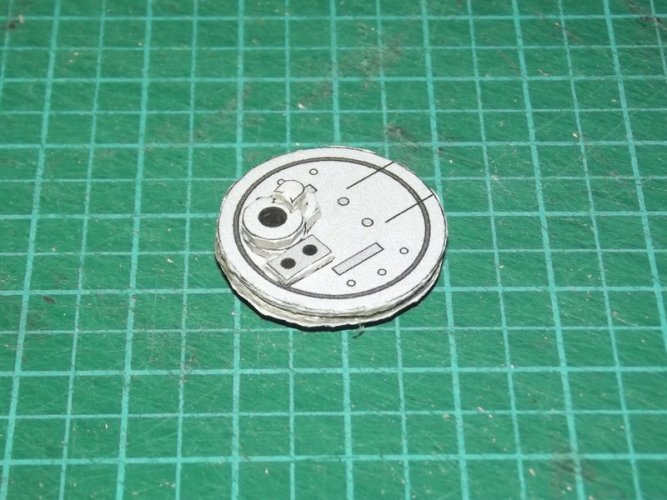
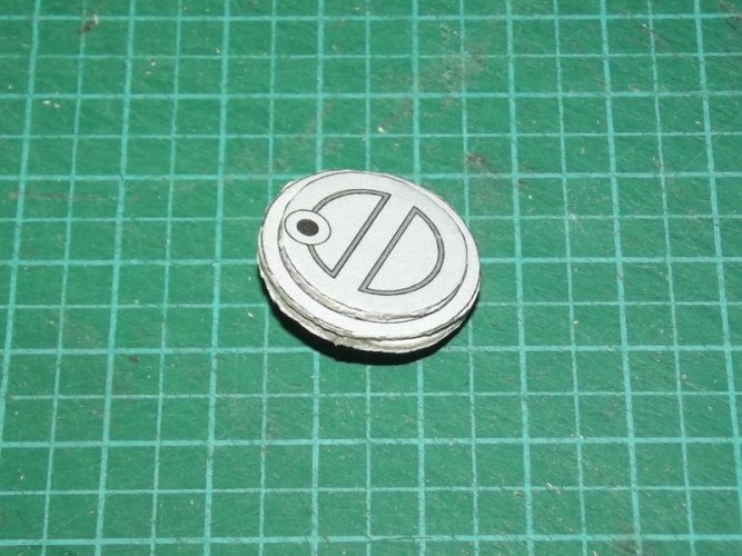
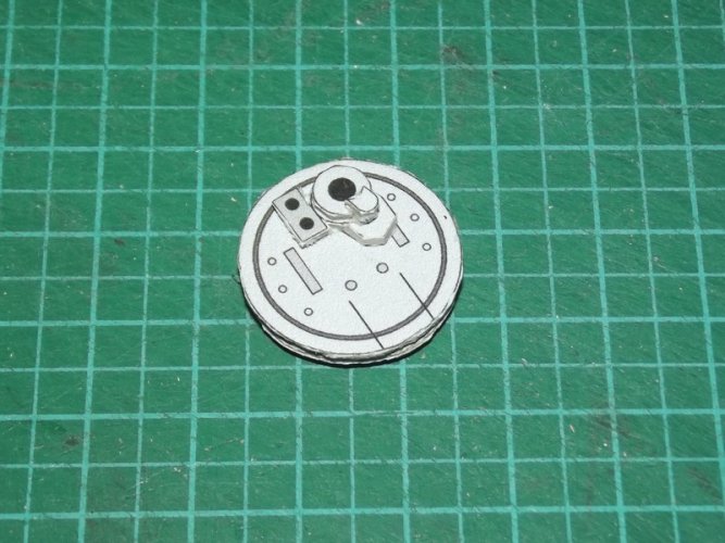
The back of the head is one of the areas which needed improvement. It was recessed and received a series of laminated parts:

DSCF1719.jpg

DSCF1721.jpg

All components were laminted to 1mm card.

DSCF1722.jpg

DSCF1723.jpg

DSCF1724.jpg

Basically there is no need to conceal the edges if you use grey card. Most of them won't be visible on the finished part (unless you look at it closely, of course ;) ).

DSCF1725.jpg

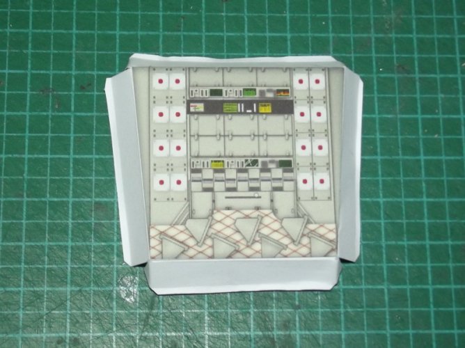
The back side of the cockpit interior from UHU02's kit was glued to the reverse side of the back of the head. I resized and stretched the image to make it fit.

DSCF1726.jpg

The back was installed.

DSCF1720.jpg

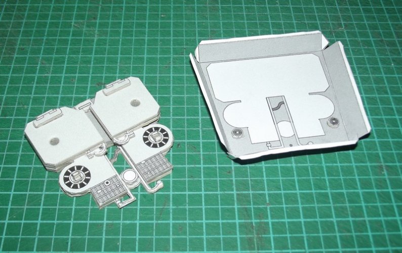
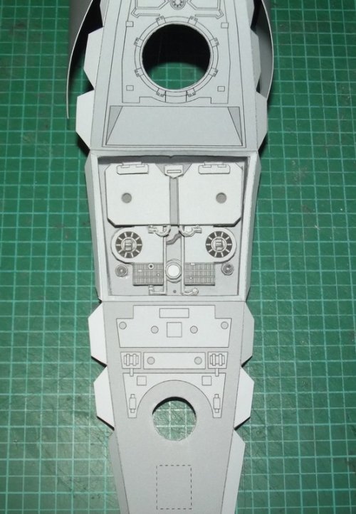
The front and top of the interior were glued to the inside of the head. This is a combination of rebuild and re-use of UHU02's walker interior. The hatch ring was copied from the top of Shunichi's head. As you can see it is a bit bigger than the hole. I painted the white area grey and resized the ring on the final plans to make it fit. You will never see anything of the fix on the finished model. ;)

DSCF1728.jpg

The neck tube was installed. Here I followed a technique I learned from Julius Perdana. The tube is pushed through the hole and the tabs are glued to the inside of the head. A view from the outside:

DSCF1729.jpg

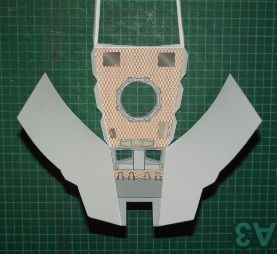
Another part from UHU02's AT-ST was laminated to the floor of the interior. It conceals the hole for the neck tube and its flaps. The graphics might be changed because I think the seat positions are too close to the front. We'll get back to it later.

DSCF1730.jpg

The head remains in this open state for the time being. I need it as a mockup to check the size and position of the other parts of the model.
 

Revell-Fan

Co-Administrator
Staff member
Administrator
Moderator
Aug 1, 2009
11,609
12,349
228
Vreden
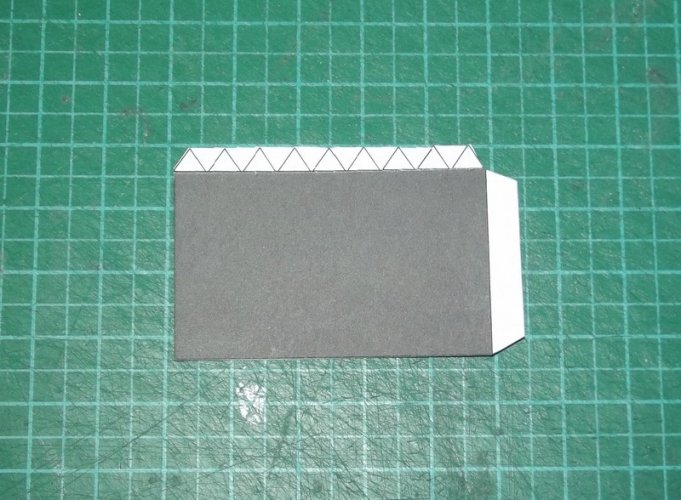
The "eye lids" are made of three basic parts:

DSCF1732.jpg

Due to a logic error (I mirrored already mirrored parts :hammerhead:) I had more parts for one lid and too few parts for the other. I put them to good use and used them for laminations. In the end I found these extra parts necessary for the overall look so the final plans will have twice the amount of lid parts. Sorry, no picture of the finished eyes yet because I'll need to print the missing parts for the other lid. ;)
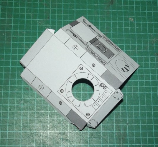
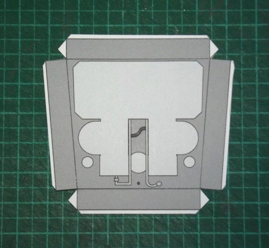
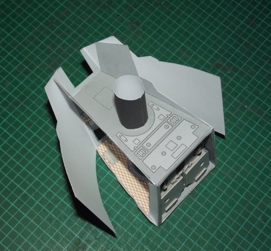
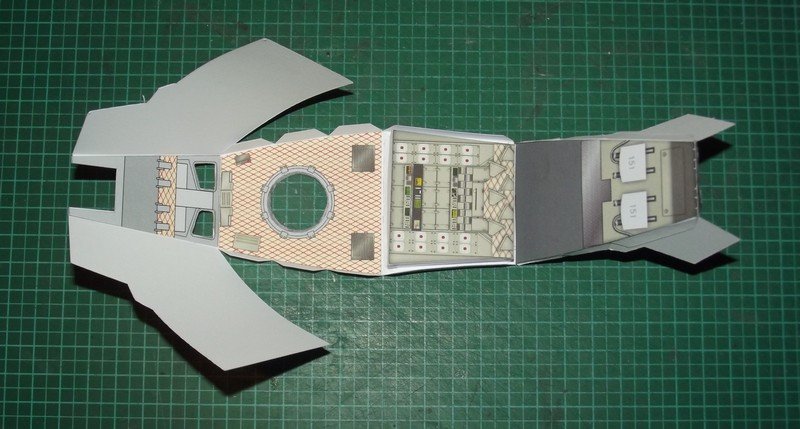
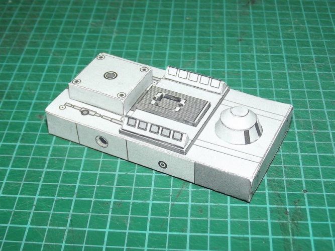
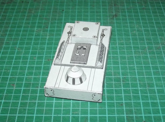
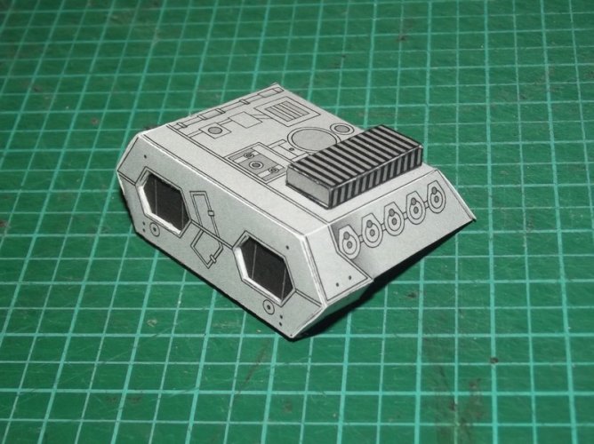
Next we have the engine box. It is what it is, a simple box with some deco parts on it. I changed the original assembly to simplify it and to get a fully closed box. On the original version several areas were left open and you could look inside the model.

DSCF1746.jpg

I marked the positions of the hip joints with a circle. The joints will be movable so you have to use some pegs made of wooden rods or wire. The size of the hole you will have to punch through the parts depends on the size of the rods you are going to use. For this reason the circle is just meant to act as a guide. It is important to hit the center of the hole, so I added a cross to make this task easier for you.

DSCF1747.jpg

The back side of the future holes are reinforced with card.

DSCF1748.jpg

I used a holepunch to create the holes which worked just fine. :)
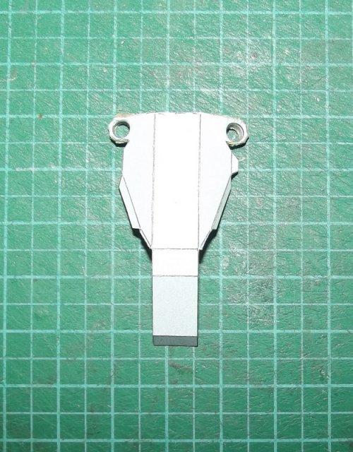
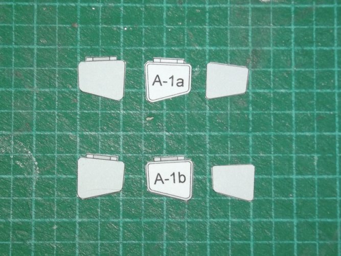
Laminations for @Rhaven Blaack : ;)

DSCF1738.jpg

DSCF1739.jpg

DSCF1740.jpg

DSCF1745.jpg

DSCF1749.jpg

DSCF1750.jpg

DSCF1751.jpg

The box gets a cover:

DSCF1741.jpg

DSCF1742.jpg

The "exhaust ports" or vents are recessed.

DSCF1743.jpg

DSCF1744.jpg

As it turned out the cover does not fit well over the box so one of the parts needs to be adjusted.
 
Last edited:

Revell-Fan

Co-Administrator
Staff member
Administrator
Moderator
Aug 1, 2009
11,609
12,349
228
Vreden
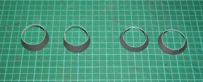
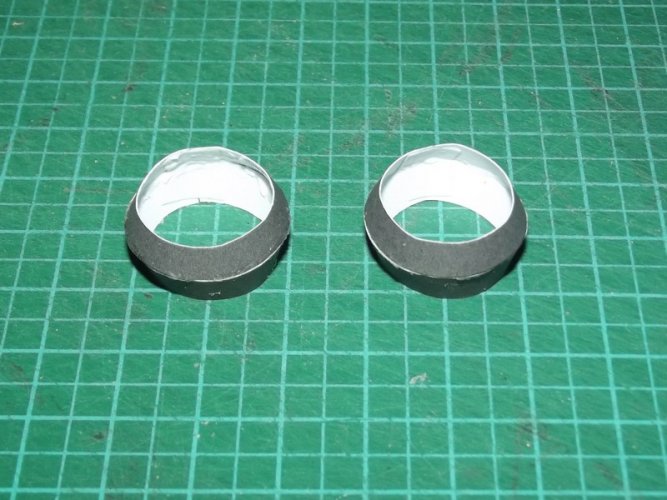
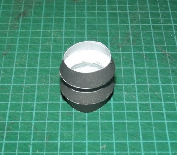
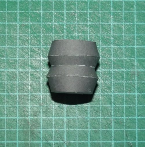
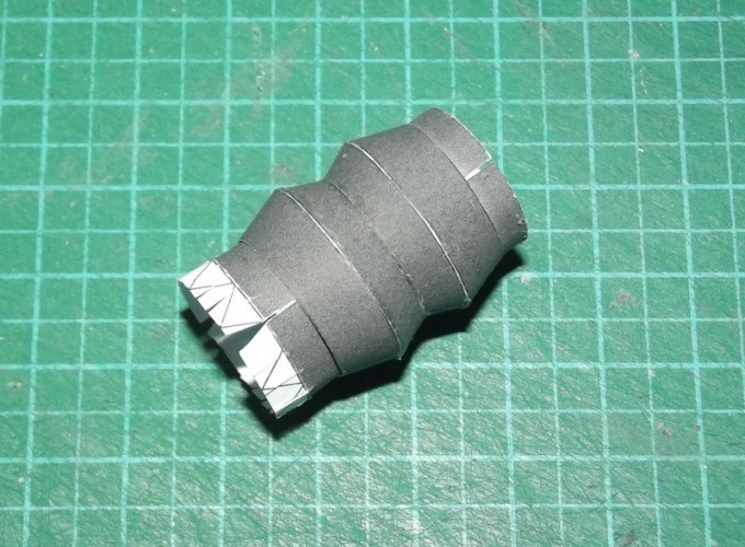
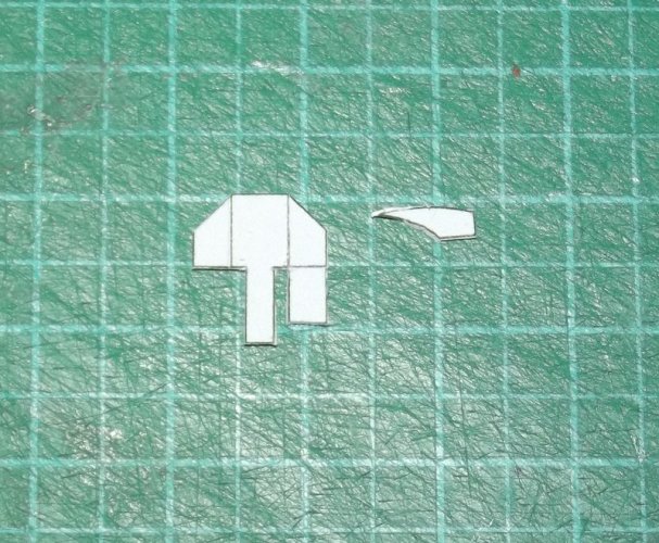
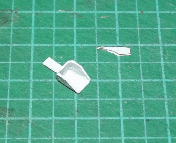
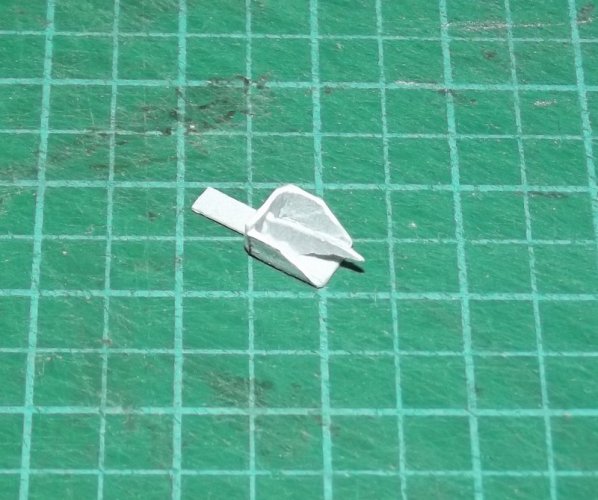
The neck is a simple tube which is pushed through the hole in the engine box and glued to its bottom. The original filming miniature features two cup-like shapes which are stacked on top of each other with the top cup being flipped so that the short ends of them meet in the middle of the neck. I replicated this with a gradient on the tube, however, as this project progressed, I tried to fully flesh this out in 3D.

So I made some easy cups in SketchUp and unfolded them into this:

DSCF1752.jpg

DSCF1753.jpg

DSCF1754.jpg

DSCF1755.jpg

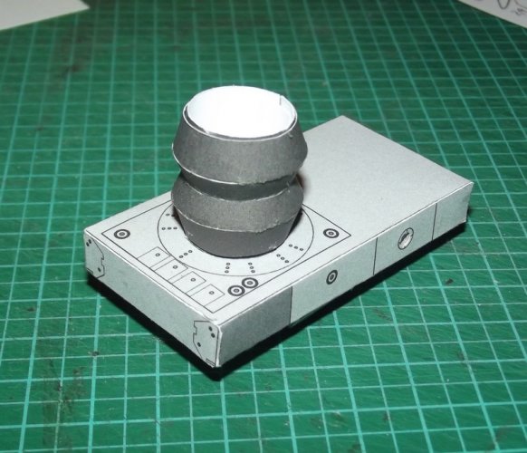
This was pushed over the neck tube:

DSCF1756.jpg

The neck tube is inserted into the engine box:

DSCF1757.jpg

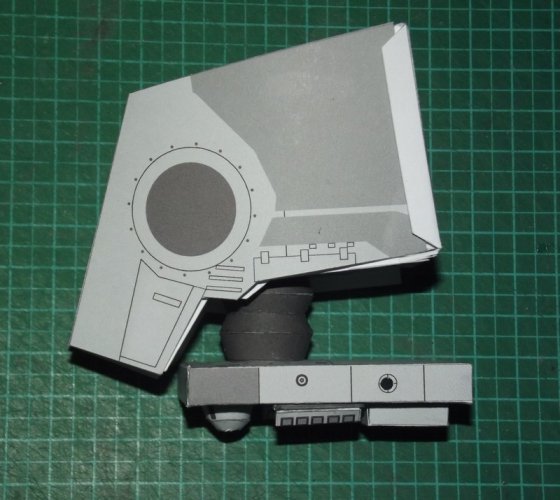
and the tube protruding from the bottom of the head is pushed inside the engine box tube:

DSCF1758.jpg

Everything fits nicely and the head rotates! :)

I decided to keep the neck tube on the engine box to give the head tube a smooth surface for rotation. If I had skipped it the tube might get locked up inside the double cups. In addition the tube inside the cups gives them more stability.

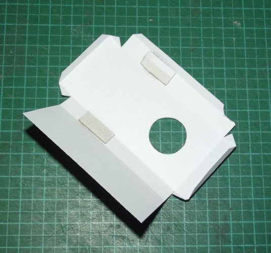
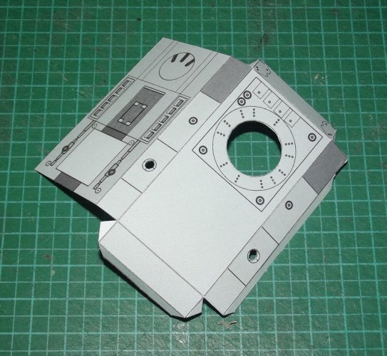
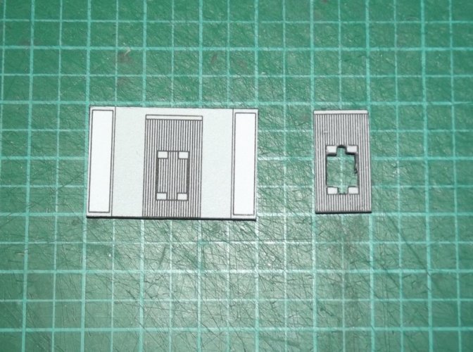
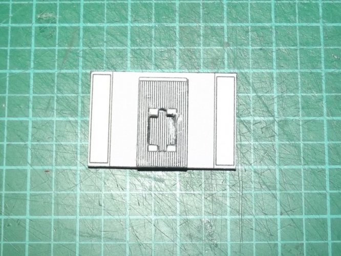
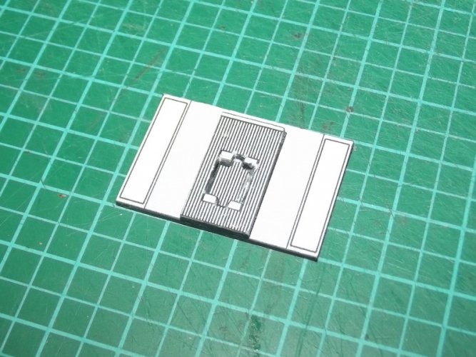
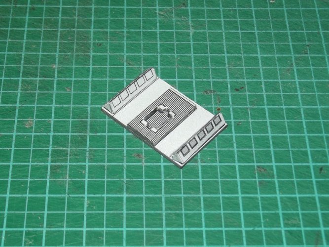
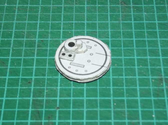
Now come some picture of single components I finished to "get them out of the way":

The top hatch:

DSCF1761.jpg

DSCF1762.jpg

DSCF1763.jpg

DSCF1764.jpg

DSCF1765.jpg

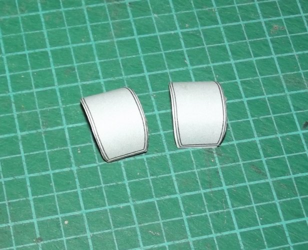
The "knee pads":

DSCF1760.jpg

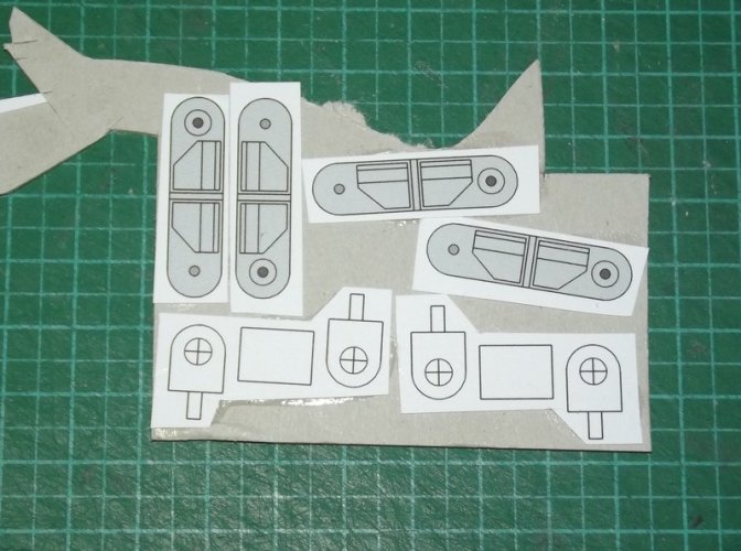
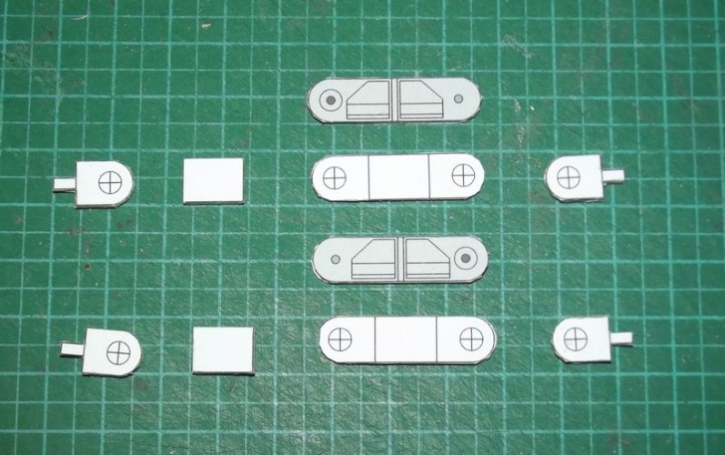
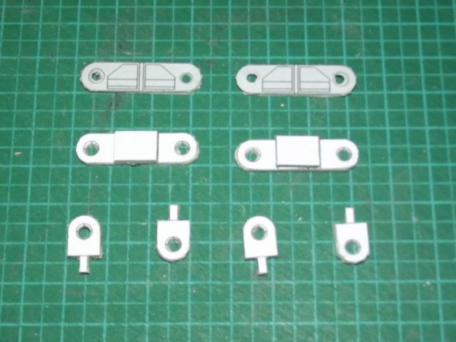
And the hip joints:

DSCF1759.jpg

DSCF1766.jpg

DSCF1767.jpg

More on them later. :)
 
Last edited:

Revell-Fan

Co-Administrator
Staff member
Administrator
Moderator
Aug 1, 2009
11,609
12,349
228
Vreden
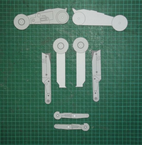
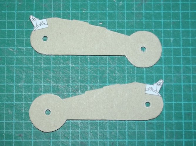
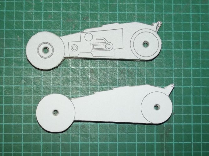
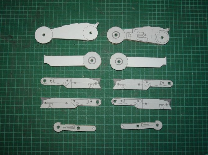
The new legs are fully articulated and posable. Each leg consists of three basic parts which are laminated to card:

DSCF1733.jpg

DSCF1734.jpg

The small texture bit is laminated to the back to prevent the plain card from being seen later:

DSCF1735.jpg

DSCF1736.jpg

DSCF1737.jpg

Do not worry about the plain look of the upper leg. It will be covered by a separate piece which will make any trace of the joint pin invisible. :)

Three pieces are used to make the middle legs. I'll show you a picture later. The lower legs are complete. ;)

One of the most obvious changes are the feet. I used the ones from momirfarroq's kit and traced the parts in Corel.

11.jpg

I had no idea how the parts would interact and made a quick and dirty test:

DSCF1768.jpg

Some unnecessary parts were cut off. As you can see I designed a more accurate fence cutter (middle toe).

DSCF1769.jpg

The inner beams were laminated to card, glued to the back and punched:

DSCF1771.jpg

DSCF1772.jpg

At this point things went really well:

DSCF1773.jpg

DSCF1774.jpg

I was amazed to see that my traced parts fit so well together.

DSCF1775.jpg

DSCF1777.jpg

DSCF1778.jpg

DSCF1779.jpg

DSCF1780.jpg

DSCF1781.jpg

DSCF1782.jpg

This foot is a massive improvement over the one that comes with Shunichi's kit. However, it has one major flaw: The toes do not touch the ground.

That must be changed. Now that I knew how the parts go together it was very easy to line them up in 2D to produce a more authentic look:

12.jpg

I'm now figuring out a new shape of the toe section and will keep you posted on my progress. Stay tuned! :)
 
Last edited: