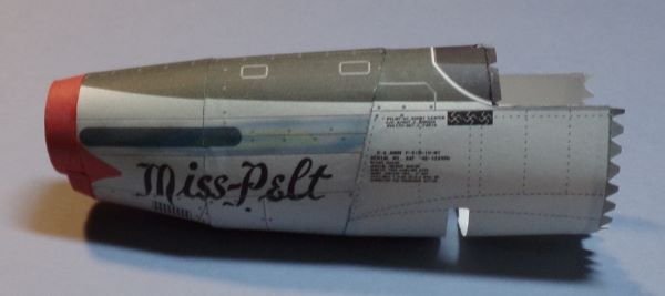
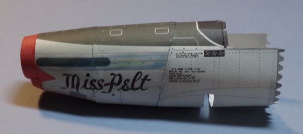
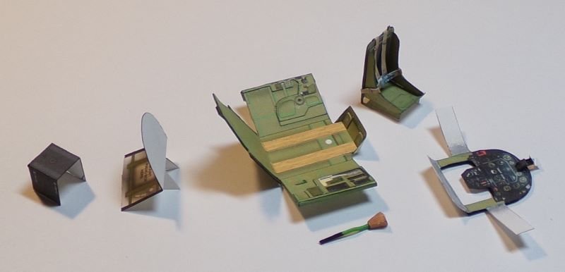
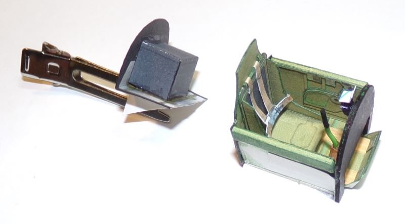
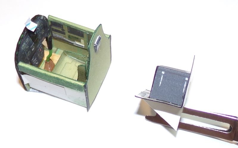
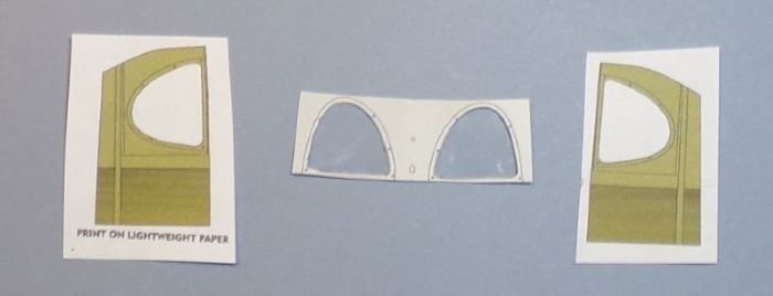
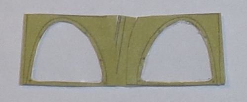
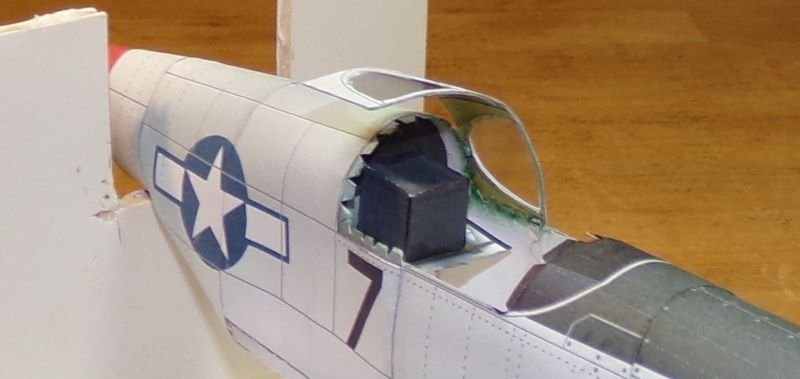
The P-51B Miss Pelt is one of many Mustang models offered by Dave's Card Creations. The Miss Pelt was flown in World War 2 by Tuskegee Airman Lt. Clarence "Lucky" Lester. This model has 5 pages of parts and 3 pages of assembly instructions with several construction diagrams. Features include a detailed cockpit and landing gear with graphic well wheel inserts. There is a full page of parts, consisting of formers and internal wing structures, that need to be printed out on regular paper and then laminated to 1 mm thick card.

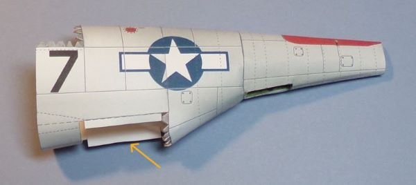
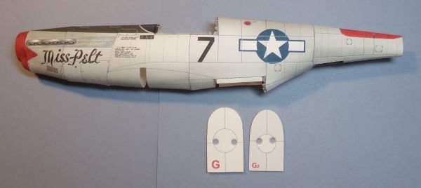
On World War 2 aircraft, I first build the front half of the fuselage from front to back and then build the rear half of the fuselage from back to front. The 2 subassemblies are then joined in the middle.
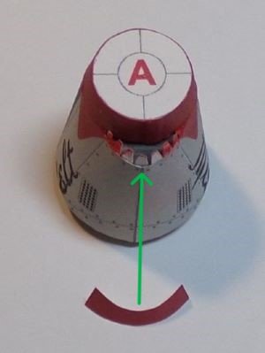
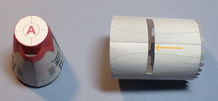
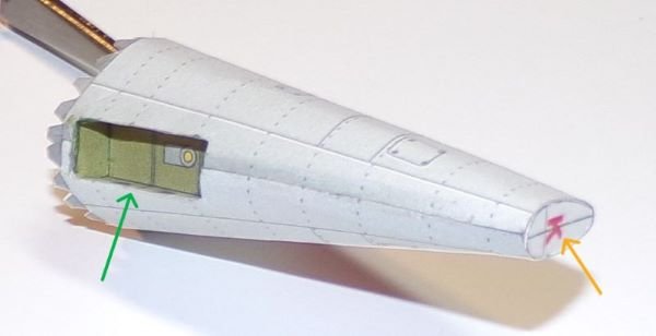
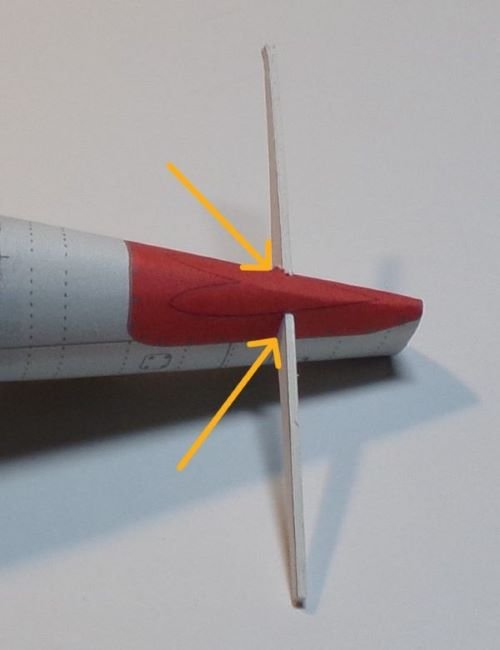
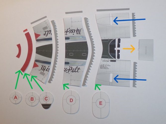
Assembling and connecting the fuselage sections is done using the supplied joiner strips. Internal formers are then inserted into the fuselage and positioned at the joints (see the green arrows). An exception to this assembly method is the joint between the first 2 sections (parts 1 and 3). A joiner strip is not provided for this connection, but formers B and C can be butt joined together.
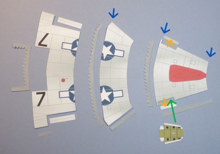
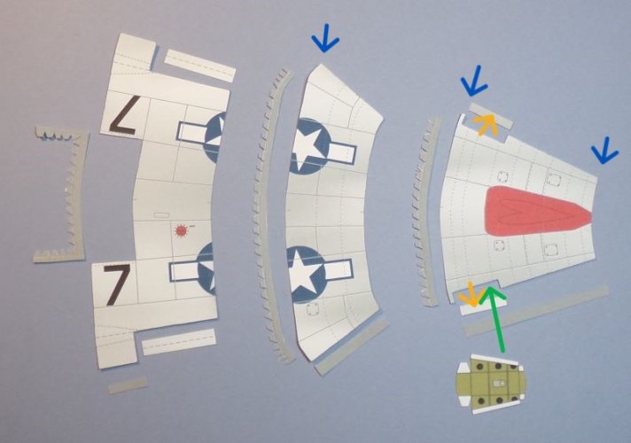
A rectangle (marked "REMOVE") in part 5 needs to be cut out to accommodate the cockpit (see the yellow arrow). There is a slot on both ends of part 5 (see the blue arrows) that also needs to be cut out. These small slots will join together to became 1 large slot for the wing assembly. I didn't cut the slots all the way to the edges to make joining the edges easier. Once the edges are joined, I will finish cutting out the slot(s).


