P-51B Mustang Miss Pelt 1/33 scale

flpaperguy

Active Member
Nov 9, 2023
84
305
40
66
Central Florida, USA
The P-51B Miss Pelt is one of many Mustang models offered by Dave's Card Creations. The Miss Pelt was flown in World War 2 by Tuskegee Airman Lt. Clarence "Lucky" Lester. This model has 5 pages of parts and 3 pages of assembly instructions with several construction diagrams. Features include a detailed cockpit and landing gear with graphic well wheel inserts. There is a full page of parts, consisting of formers and internal wing structures, that need to be printed out on regular paper and then laminated to 1 mm thick card.

mp-img1.jpg


On World War 2 aircraft, I first build the front half of the fuselage from front to back and then build the rear half of the fuselage from back to front. The 2 subassemblies are then joined in the middle.

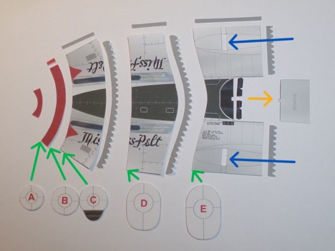
Assembling and connecting the fuselage sections is done using the supplied joiner strips. Internal formers are then inserted into the fuselage and positioned at the joints (see the green arrows). An exception to this assembly method is the joint between the first 2 sections (parts 1 and 3). A joiner strip is not provided for this connection, but formers B and C can be butt joined together.

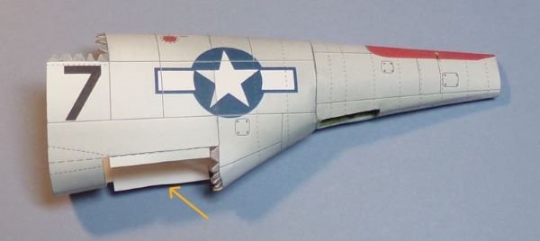
A rectangle (marked "REMOVE") in part 5 needs to be cut out to accommodate the cockpit (see the yellow arrow). There is a slot on both ends of part 5 (see the blue arrows) that also needs to be cut out. These small slots will join together to became 1 large slot for the wing assembly. I didn't cut the slots all the way to the edges to make joining the edges easier. Once the edges are joined, I will finish cutting out the slot(s).
mp-img2.jpg
 

flpaperguy

Active Member
Nov 9, 2023
84
305
40
66
Central Florida, USA
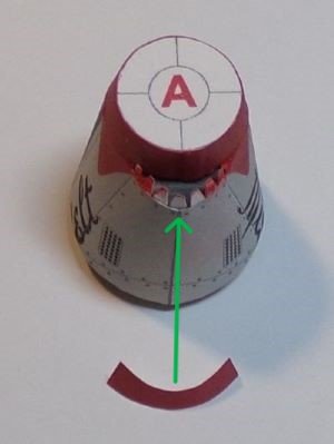
As mentioned in my previous post, a joiner strip is not provided to connect the first 2 sections of the fuselage (parts 1 and 3), but formers B and C can be butt joined together. I am not good at making smooth butt joints so I made a tabbed joiner strip for the front of the second section (part 3). After the joiner strip was glued in place, I inserted former C and glued it in place (former B was not used). Next, I glued sections 1 and 2 together using most of the tabs of the joiner strip. The 7 tabs on the bottom, which extended past section 1, were used to glue the air scoop part in place (see green arrow).

mp-img3.jpg


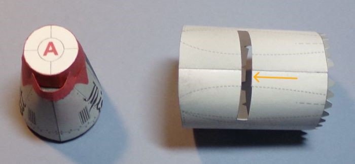
Here is the finished air scoop. Before shaping and gluing the edges of the fourth section (part 5) together, I partially cut the slots on the edges. After the part was constructed, I finished the cutting to make 1 long slot. The wing spar will be inserted into this slot (see the yellow arrow).

mp-img4.jpg
 

flpaperguy

Active Member
Nov 9, 2023
84
305
40
66
Central Florida, USA
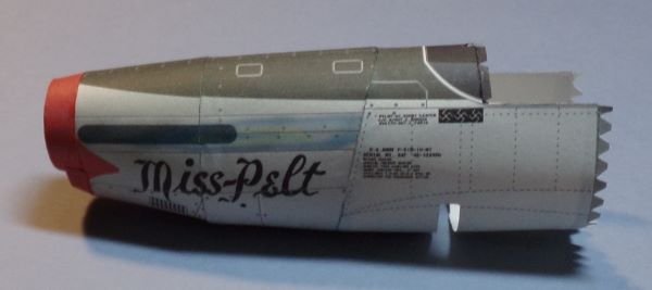
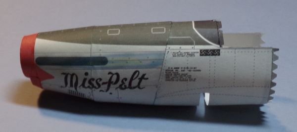
Finished the front half of the fuselage.

mp-img5.jpg


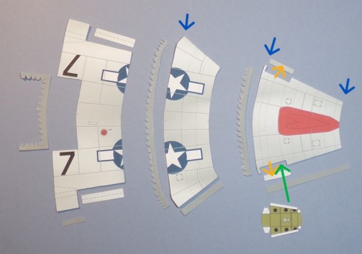
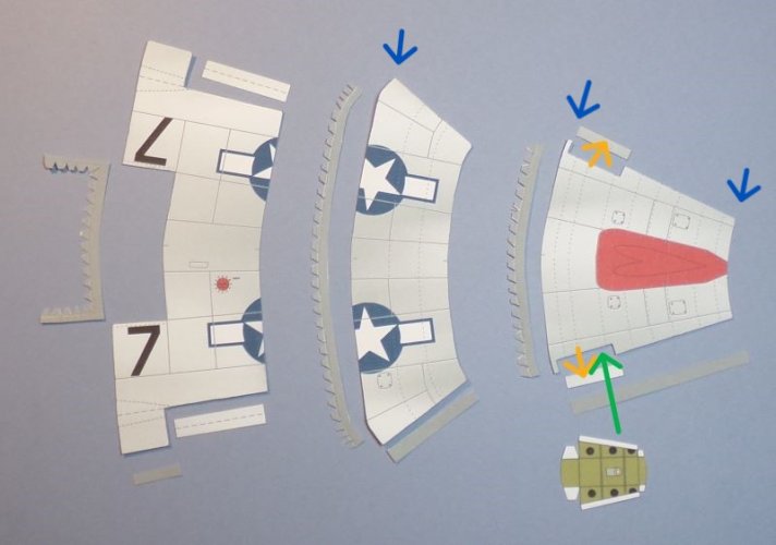
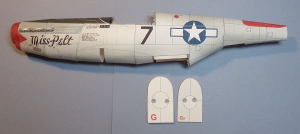
The rear half of the fuselage has 3 segments. Each segment has a glue tab along the edge and the front. I am making this model with landing gear, so I cut out the rear landing gear doors (see the yellow arrows). The rear wheel well will be located under this opening (see the green arrow). This subassembly has 3 former, which I forgot to include in this photo, but the formers positions are indicated by the blue arrows.

mp-img6.jpg
 

flpaperguy

Active Member
Nov 9, 2023
84
305
40
66
Central Florida, USA
Finished the front half of the fuselage

mp-img5.jpg


The rear half of the fuselage has 3 segments. Each segment has a glue tab along the edge and the front. I am making this model with landing gear, so I cut out the rear landing gear doors (see the yellow arrows). The rear wheel well will be located under this opening (see the green arrow). This subassembly has 3 former, which I forgot to include in this photo, but the formers positions are indicated by the blue arrows.

mp-img6.jpg
 

flpaperguy

Active Member
Nov 9, 2023
84
305
40
66
Central Florida, USA
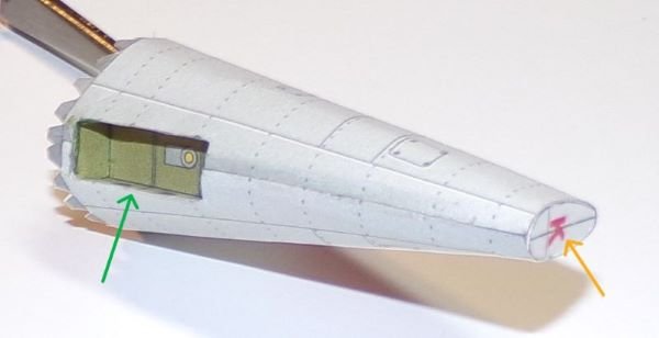
The rear most segment of the fuselage (part 9) needs some additional work after it is glued into a cone shape. The K former needs to be glued into the back end (see the yellow arrow). The rear landing gear wheel well is installed into the front end (see the green arrow).

mp-img7.jpg


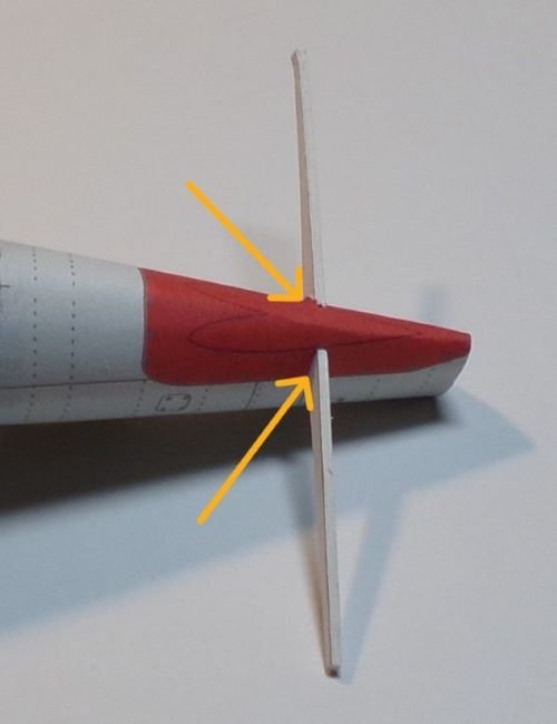
There are 2 short black lines at the top of this segment, which indicates where the slots need to be cut for the elevator former (see the yellow arrows).

ms-img8.jpg
 

micahrogers

Moderator "Where am I, and how did I get here?"
Staff member
Moderator
Jul 12, 2012
3,772
4,639
113
Shannon GA
This is looking GREAT :BRAVO: My Fav Mustang is the A-36 Apache, The ground attack variant of the Allison powered Mustangs. They had one outside the visitors center by the parade grounds at Lackland AFB in the 70's
 

flpaperguy

Active Member
Nov 9, 2023
84
305
40
66
Central Florida, USA
This is looking GREAT :BRAVO: My Fav Mustang is the A-36 Apache, The ground attack variant of the Allison powered Mustangs. They had one outside the visitors center by the parade grounds at Lackland AFB in the 70's
I don't remember seeing the Apache when I was stationed at Lackland from 1984 to 1992, so they must have replaced it before I got there. I am fond of all Mustangs .
 

micahrogers

Moderator "Where am I, and how did I get here?"
Staff member
Moderator
Jul 12, 2012
3,772
4,639
113
Shannon GA
I don't remember seeing the Apache when I was stationed at Lackland from 1984 to 1992, so they must have replaced it before I got there. I am fond of all Mustangs .
I spent a lot of my days after school out there looking at all the planes. My dad was a SP, and then SP Training instructor there, first got there in 74, and left in 80. and they changed aircraft out in the time I was there.
 

flpaperguy

Active Member
Nov 9, 2023
84
305
40
66
Central Florida, USA
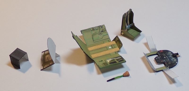
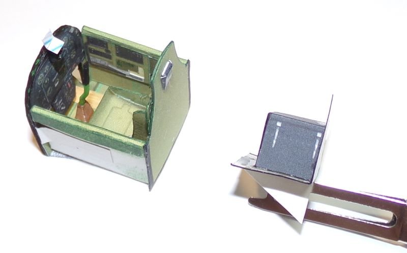
Now that the formers at the rear of the cockpit are in place it is time to do the cockpit assembly. The radio box and shelf are 2 simple parts (on the left in the photo). The cockpit itself consists of 4 subassemblies: the tub, which has several little 2D parts that are glued to the inside, the control stick, the pilot seat and the instrument panel.


mp-img13.jpg


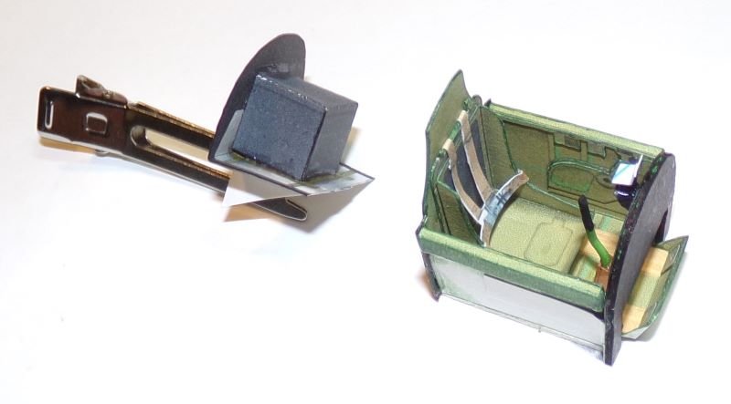
Here are two views of the assembled cockpit and radio assemblies.

mp-img14.jpg

mp-img15.jpg
 

flpaperguy

Active Member
Nov 9, 2023
84
305
40
66
Central Florida, USA
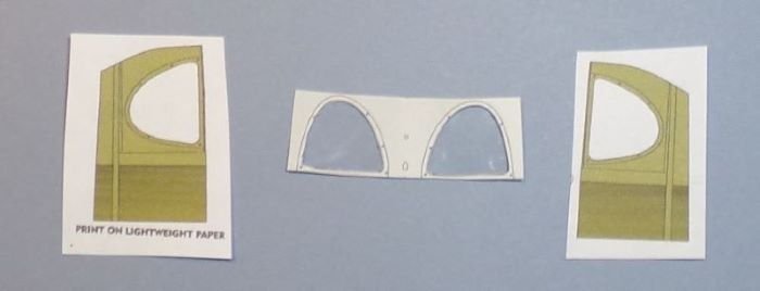
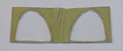
The rear window framing is 1 piece (part 7). There are 2 others green parts provided on page 3 of the instructions that can be glued to the inside surface of the window frame. These parts are intended for use when making transparent windows. I cut out pieces from an old document protector to make the transparent windows, which was my first time doing so. I used Beacon Zip Dry glue to mate the paper and plastic. This glue is thick and can be stringy if not placed carefully (it reminds me of rubber cement).

mp-img16.jpg


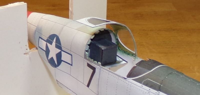
The odd black lines in the middle are a result of my using scraps to totally cover the inside wall. I don't think covering the inside was worth the effort because that area is rarely seen. The window piece can be installed before or after the cockpit is placed.

mp-img17.jpg