

I believe that most are just under 200 gsm 190 or so, but this may be a bit different... Mine measures out to be right at the same as 199 gsm, same as my standard index stock. ( mine has become a bit more weathered sitting on the shelf for all this time)!! I keep telling myself "one of these days" but that day isn't here yet!
M4A4 Sherman VC Firefly, Halinski 1:25
- Thread starter snake7
- Start date
You are using an out of date browser. It may not display this or other websites correctly.
You should upgrade or use an alternative browser.
You should upgrade or use an alternative browser.
")
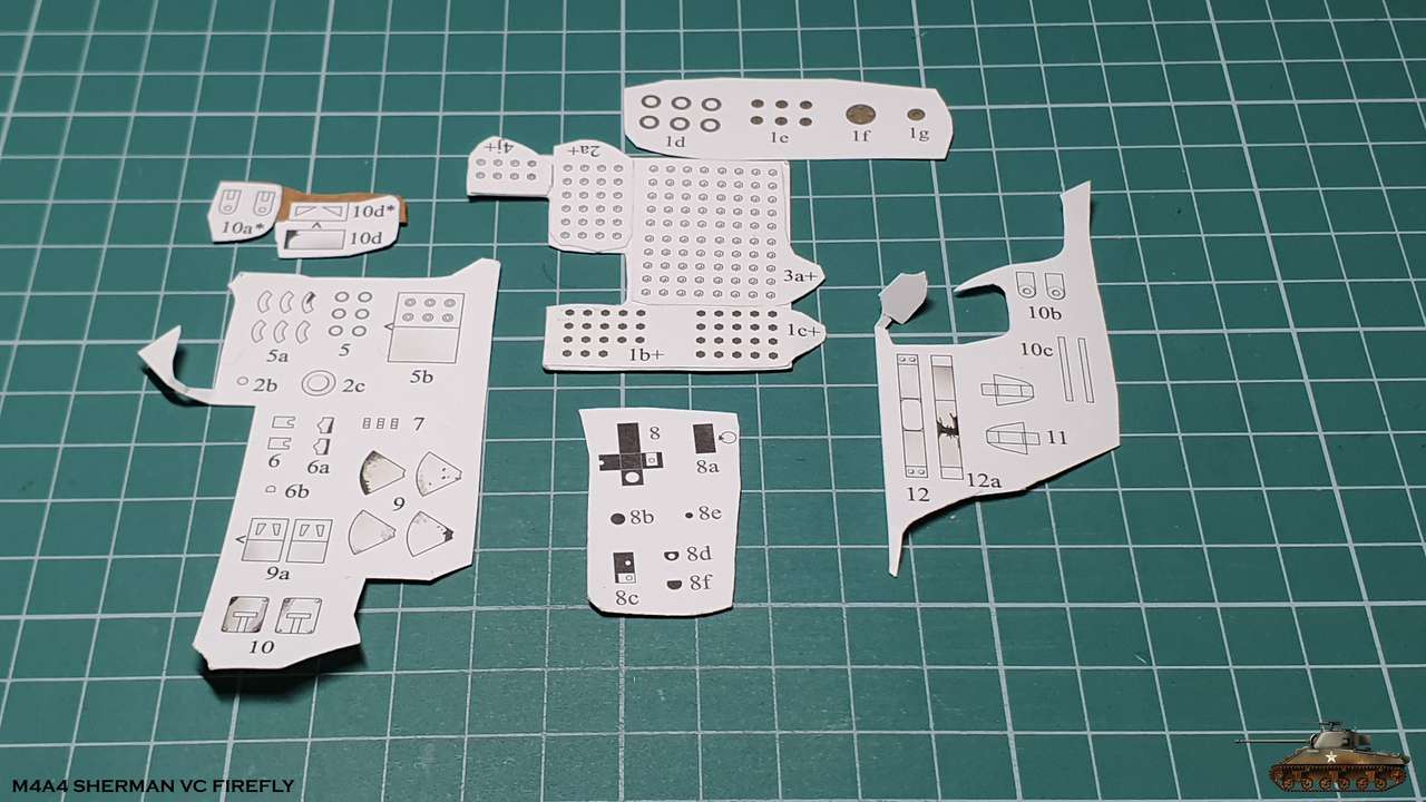
The build tempo is not as I had planned, perhaps because I again got into a bunch of small parts + templates.
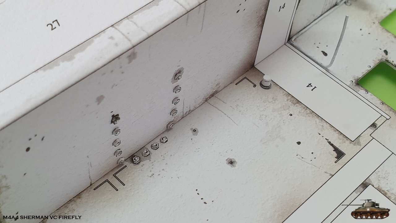
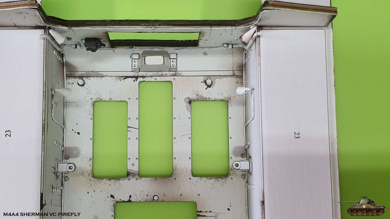
First, I added the bolt caps on the bottom front panel and some caps on the bottom of the hull
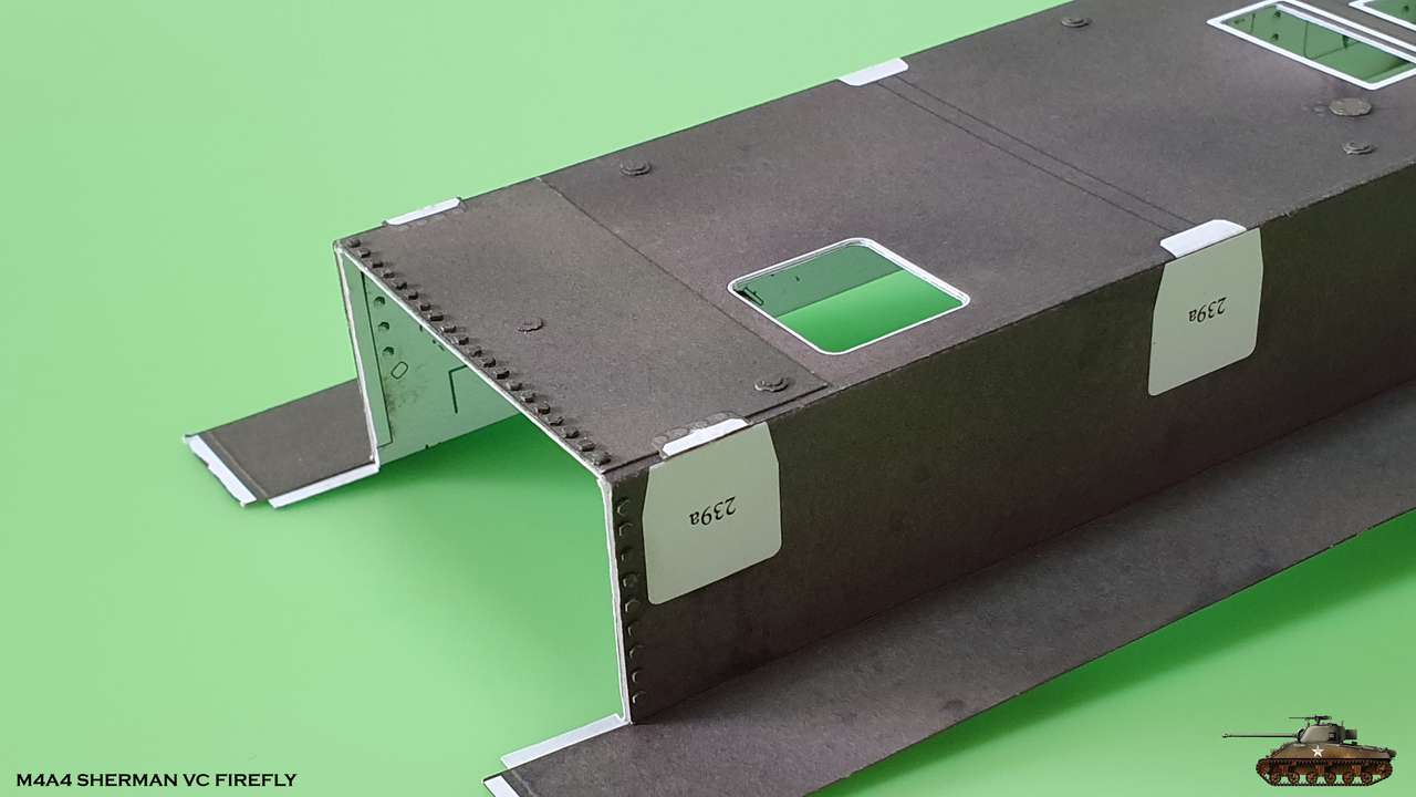
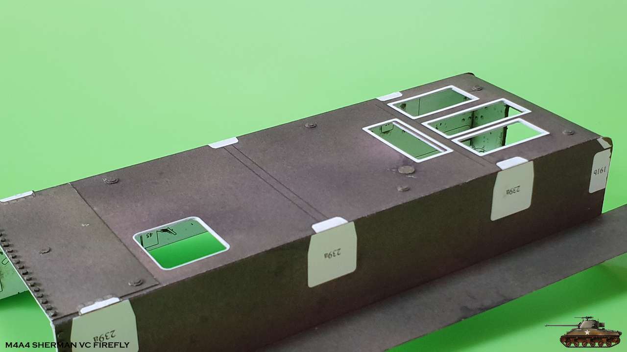
Then I began to fill the bath of a hull. A bunch of small parts ...
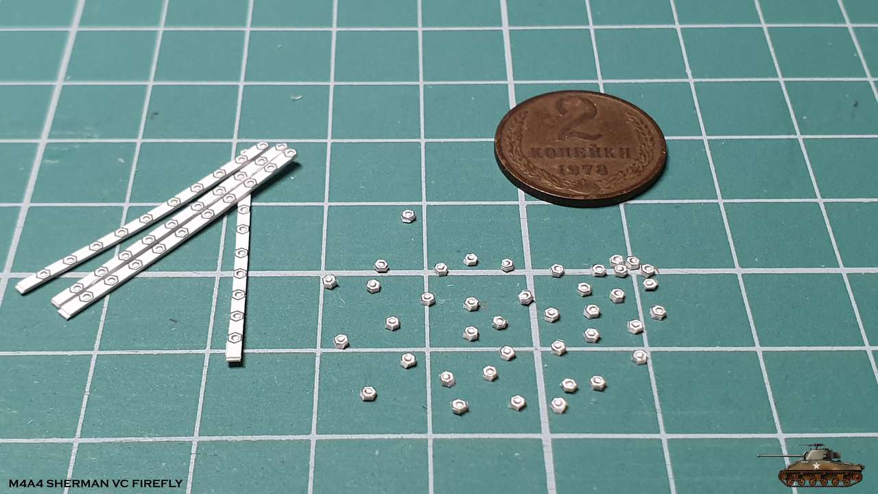
I cut the bolt caps . These bolts fasten the suspension system.
Each cap is about one millimeter.
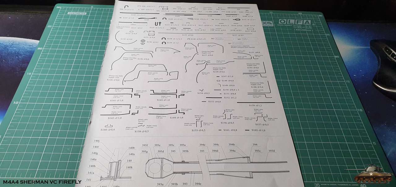
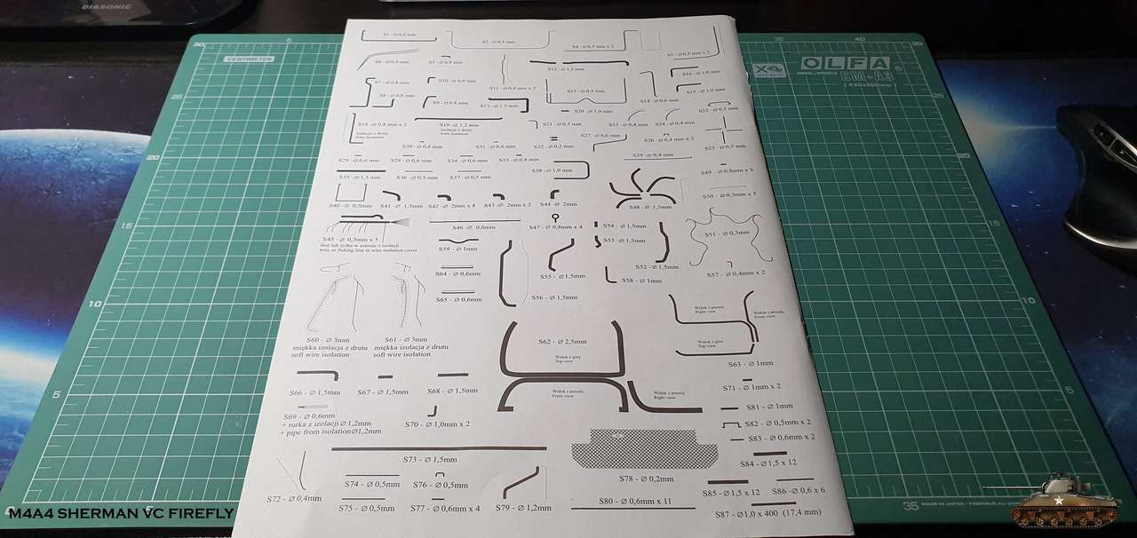
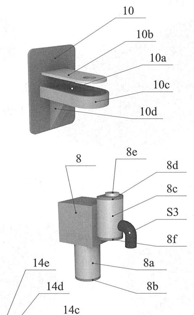
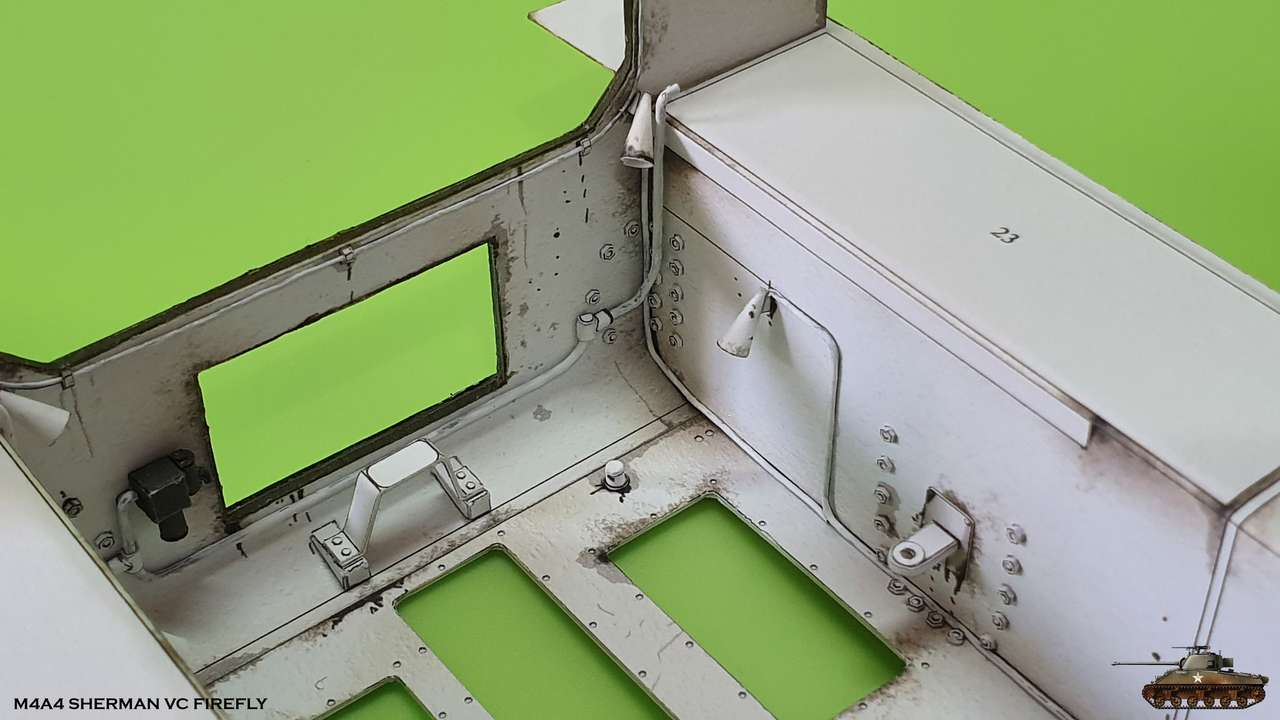
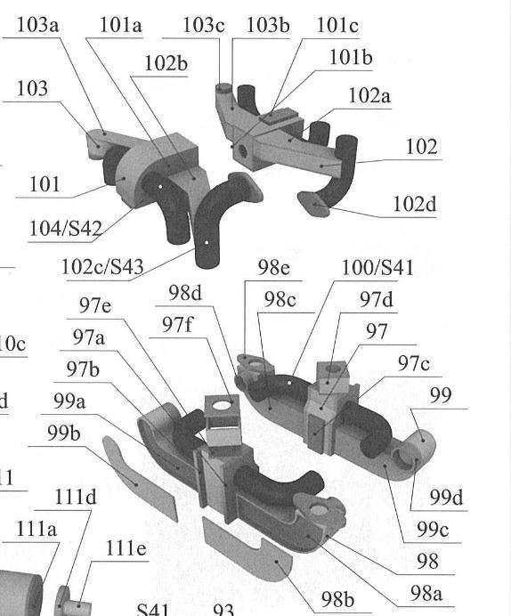
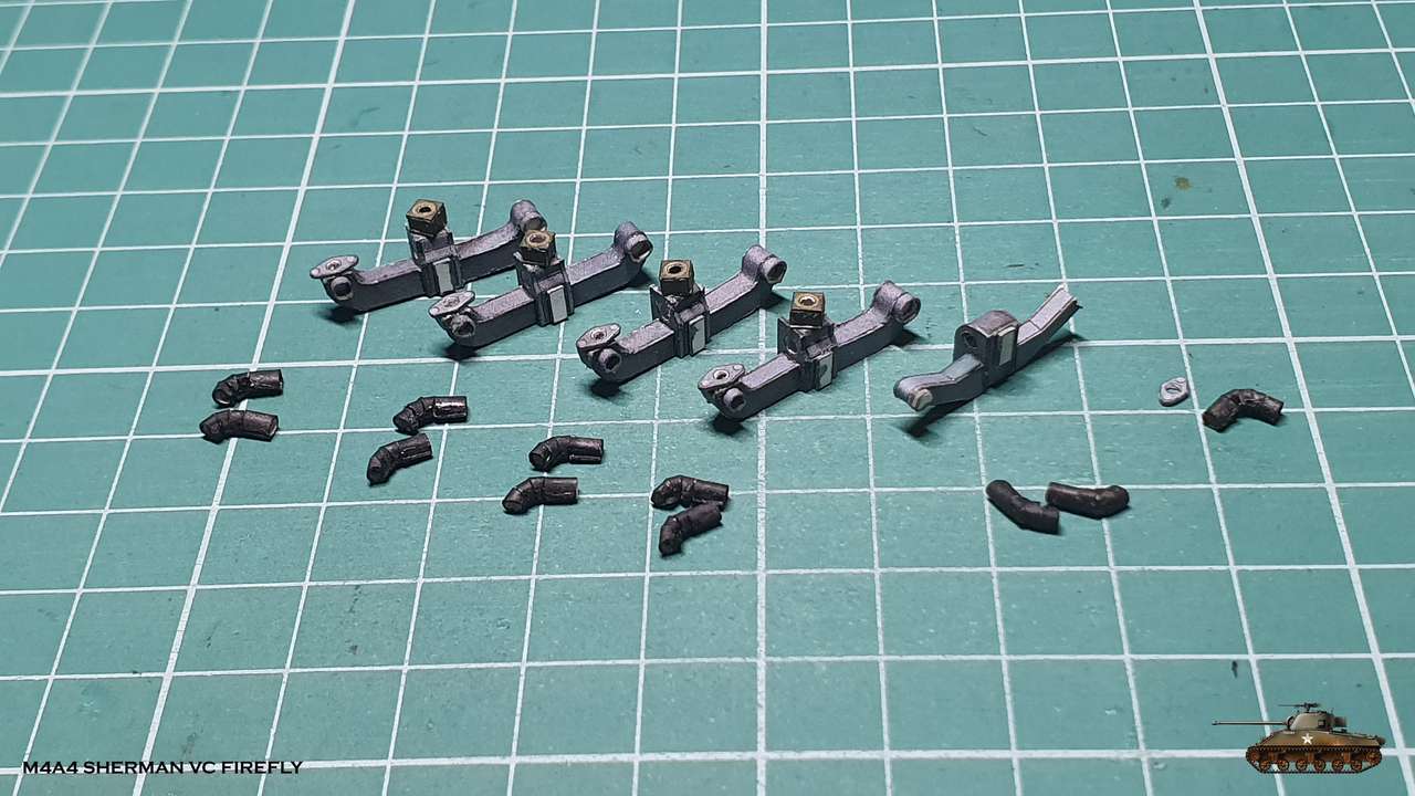
And I began to build support for the engine and fire extinguishing system + fuel line with a pump.
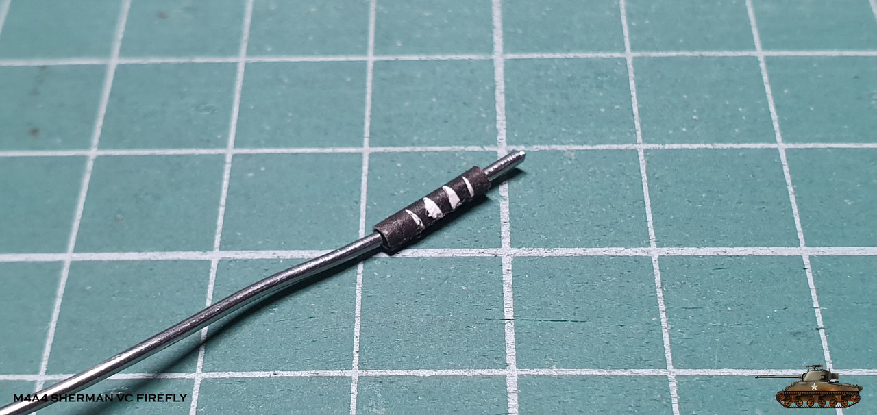
There were a lot of pipes that needed to be made from wire, and, as I had planned, I used solders of different diameters.
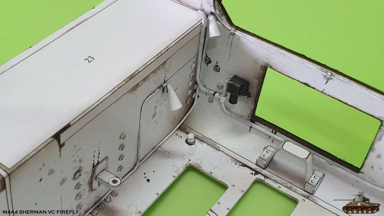
At first it was a bit difficult to create suitable forms, but with some experience I was able to easily mold all the pipes.
In a princep, working with such a wire is easy because it is soft and easily bent and can be bent at any angle with your fingers.
Only in sharp corners I used pliers.
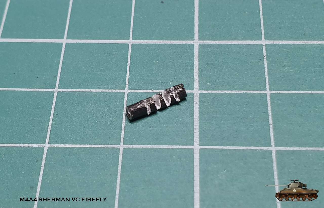
I am pleased with the result, although the parts are very fragile and require special care when gluing.
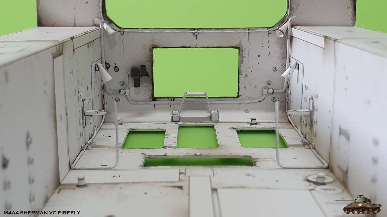
It took me a lot of patience and time to glue them in place at all these angles,
when along the way I ripped off a bunch of bolt caps that I had to stick back.
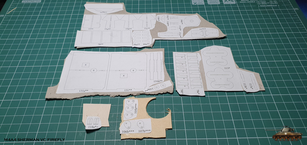
By the way, in this model, templates capture two whole pages full of drawings.
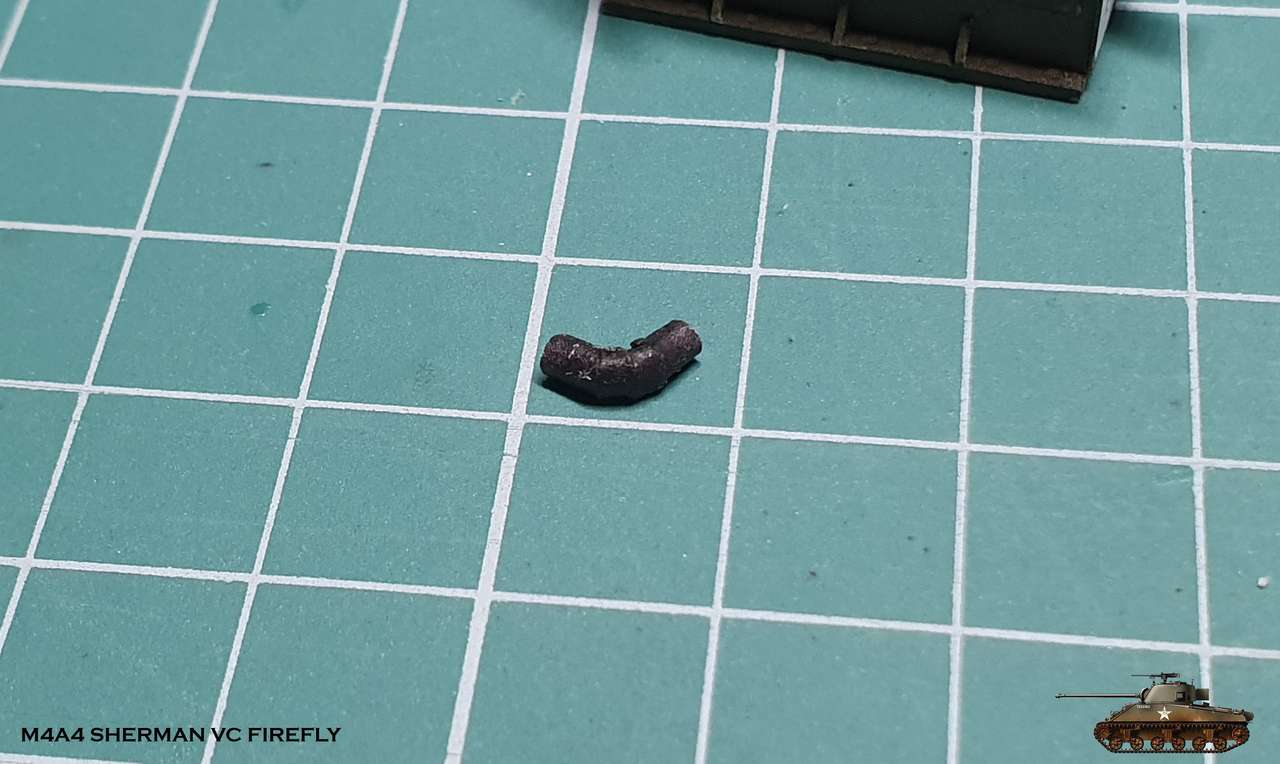
All parts are ready and assembly has begun. As a result, we got a fire extinguishing system with 4 fire extinguishers (for now) pipes,
connecting fuel tanks (futured) with the pump and engine supports.
When installing I damaged paint on the tubes here and there.
I decided not to touch it and leave it as it is because, in my opinion, it fits well with the overall weathering.
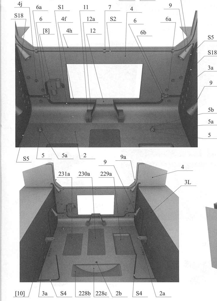


First, I added the bolt caps on the bottom front panel and some caps on the bottom of the hull
Then I began to fill the bath of a hull. A bunch of small parts ...
I cut the bolt caps . These bolts fasten the suspension system.
Each cap is about one millimeter.
And I began to build support for the engine and fire extinguishing system + fuel line with a pump.
There were a lot of pipes that needed to be made from wire, and, as I had planned, I used solders of different diameters.
At first it was a bit difficult to create suitable forms, but with some experience I was able to easily mold all the pipes.
In a princep, working with such a wire is easy because it is soft and easily bent and can be bent at any angle with your fingers.
Only in sharp corners I used pliers.
I am pleased with the result, although the parts are very fragile and require special care when gluing.
It took me a lot of patience and time to glue them in place at all these angles,
when along the way I ripped off a bunch of bolt caps that I had to stick back.
By the way, in this model, templates capture two whole pages full of drawings.
All parts are ready and assembly has begun. As a result, we got a fire extinguishing system with 4 fire extinguishers (for now) pipes,
connecting fuel tanks (futured) with the pump and engine supports.
When installing I damaged paint on the tubes here and there.
I decided not to touch it and leave it as it is because, in my opinion, it fits well with the overall weathering.
Last edited:

Exactly, with AK4. You can see it on forth picture. First of all i cut long strip with all the bolts and then just cut diagonally every unit.That is crazily awesome. How did you cut the hexagonal bolts? Just with the Xcto of AK4 knives?
It is pretty easy
- Apr 5, 2013
- 13,876
- 10,215
- 228
Thanks Zathros
After I finished with engine compartment detailing, I had several options to continue:
and if I continued and closed the engine compartment or installed the fuel tanks on the sides, it would limit access to place the engine
That's why I start the model inside the model, and this is the Chrysler engine, which consists of five blocks of 4.1, so the entire engine was 20.5 liters and produced 470 horsepower.
These engines were installed in M3A4 Lee and of course Sherman Firefly
This is how the engine looked live

And that how it should turn out of paper
The developer tried to detail it as much as possible, given the paper and scale limitations, and I am happy to assemble such a masterpiece, even if at the end half of the engine will be hidden.

Only engine has two pages of drawings
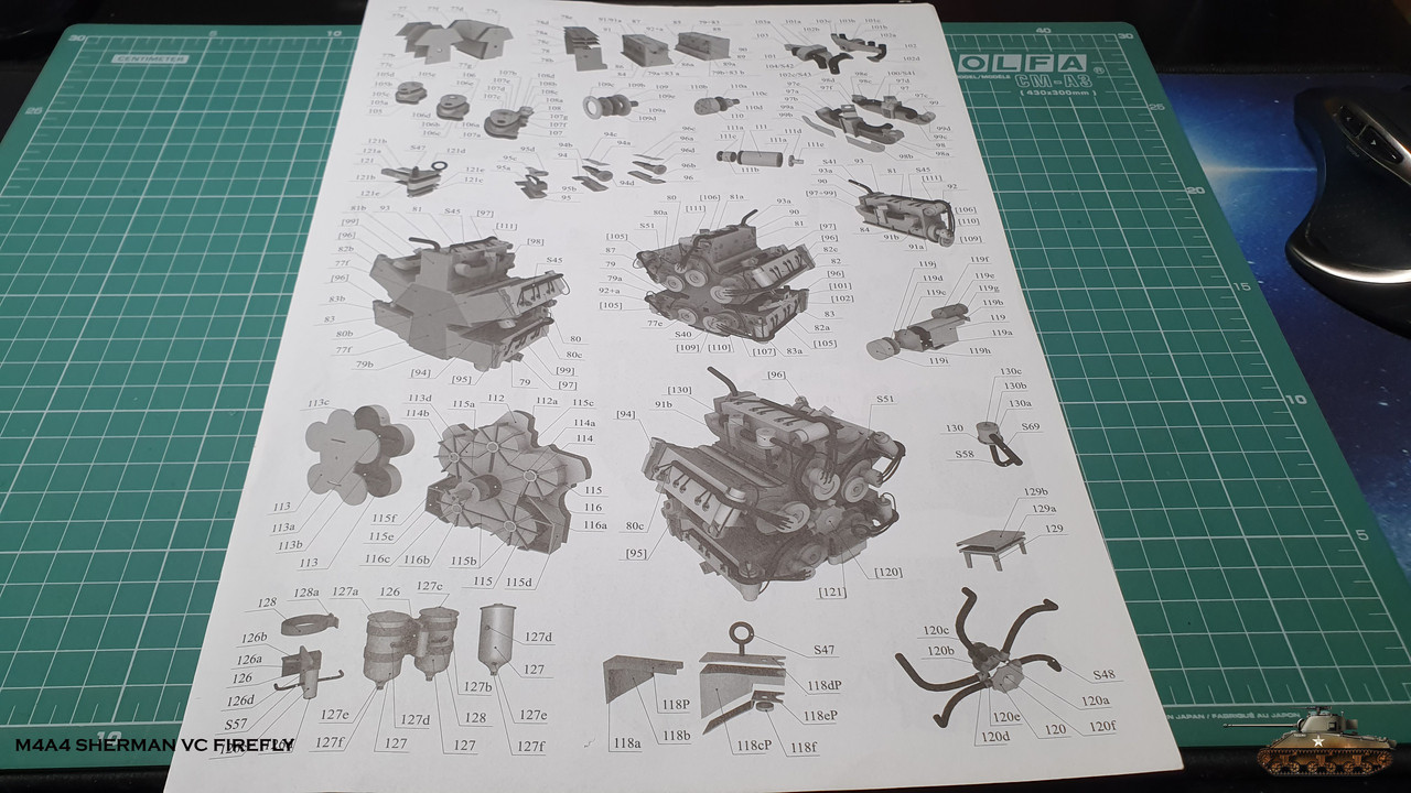
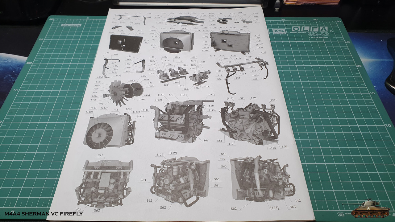
There is a great number of parts as well - a page and a half heap crammed + a lot of frame details
I had to prepare before assembling and collected all the parts from the book. It was relatively easy, because even here everything is thought out and most of the details are concentrated in one place and with the numbering in order
I glued the details of the frame to the cardboard and already managed to use four thicknesses:
0.2 (empty space on the page from the book)
0.5 (old cardboard card)
1 (specially ordered cardboard)
1.5 (cardboard from the store for building layouts)
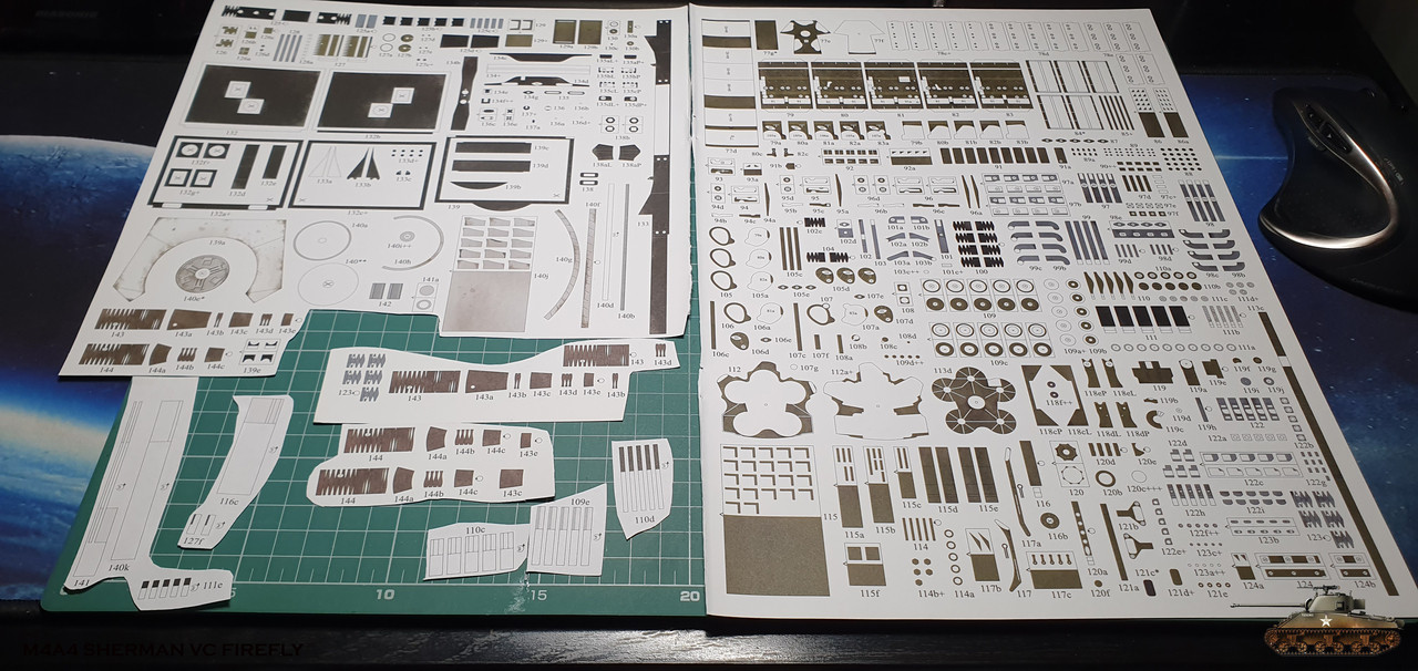
Of course, later some printed parts also will be reinforced with cardboard.
First of all, the heart of the engine is assembled and because it is the basis for all - the power frame is assembled, on which the casing is put on.
At the end of the assembly, it looks like this

To be continued...
After I finished with engine compartment detailing, I had several options to continue:
- Continue by numbers and assemble the front wall of the engine room
- Assemble the fuel tanks and install on the sides, as a continuation of the equipment of the engine room
- Start assembling engine
and if I continued and closed the engine compartment or installed the fuel tanks on the sides, it would limit access to place the engine
That's why I start the model inside the model, and this is the Chrysler engine, which consists of five blocks of 4.1, so the entire engine was 20.5 liters and produced 470 horsepower.
These engines were installed in M3A4 Lee and of course Sherman Firefly
This is how the engine looked live
And that how it should turn out of paper
The developer tried to detail it as much as possible, given the paper and scale limitations, and I am happy to assemble such a masterpiece, even if at the end half of the engine will be hidden.
Only engine has two pages of drawings
There is a great number of parts as well - a page and a half heap crammed + a lot of frame details
I had to prepare before assembling and collected all the parts from the book. It was relatively easy, because even here everything is thought out and most of the details are concentrated in one place and with the numbering in order
I glued the details of the frame to the cardboard and already managed to use four thicknesses:
0.2 (empty space on the page from the book)
0.5 (old cardboard card)
1 (specially ordered cardboard)
1.5 (cardboard from the store for building layouts)
Of course, later some printed parts also will be reinforced with cardboard.
First of all, the heart of the engine is assembled and because it is the basis for all - the power frame is assembled, on which the casing is put on.
At the end of the assembly, it looks like this
To be continued...
Last edited:
I just stumbled upon this and I have to say, WOW.
I'm definitely following this build.
That is some VERY impressive work so far.
I'm definitely following this build.
That is some VERY impressive work so far.

- Apr 5, 2013
- 13,876
- 10,215
- 228
We lost a lot of posts. There is absolutely nothing we can do about it. Tapatalk did not do their job. We now have new software, and a private, modern fast server. You can rebuild your thread if you wish, or just continue, I sure would like to see how this model turns out, it's so excellent!! thumbsup
Thanks Zathros..
I sure will continue the thread and have no problem to recover old posts. Will do it asap.
I sure will continue the thread and have no problem to recover old posts. Will do it asap.
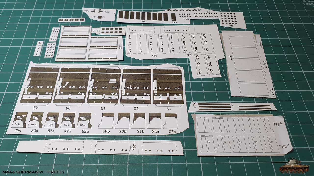
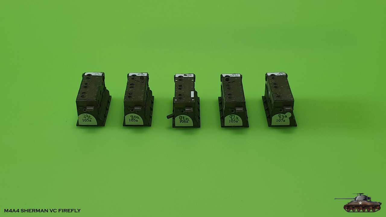
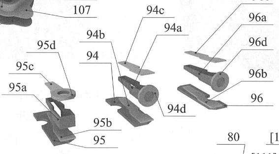
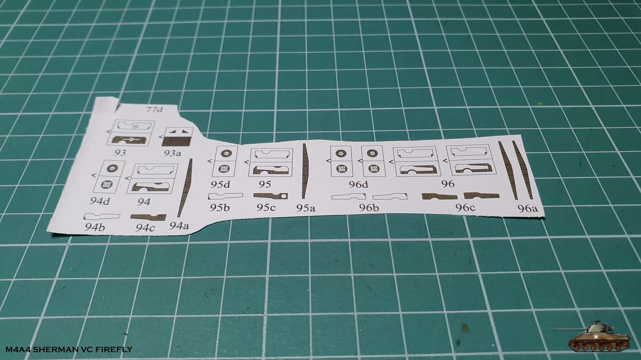
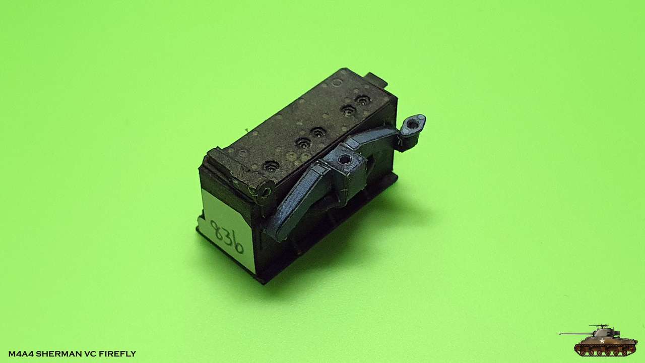
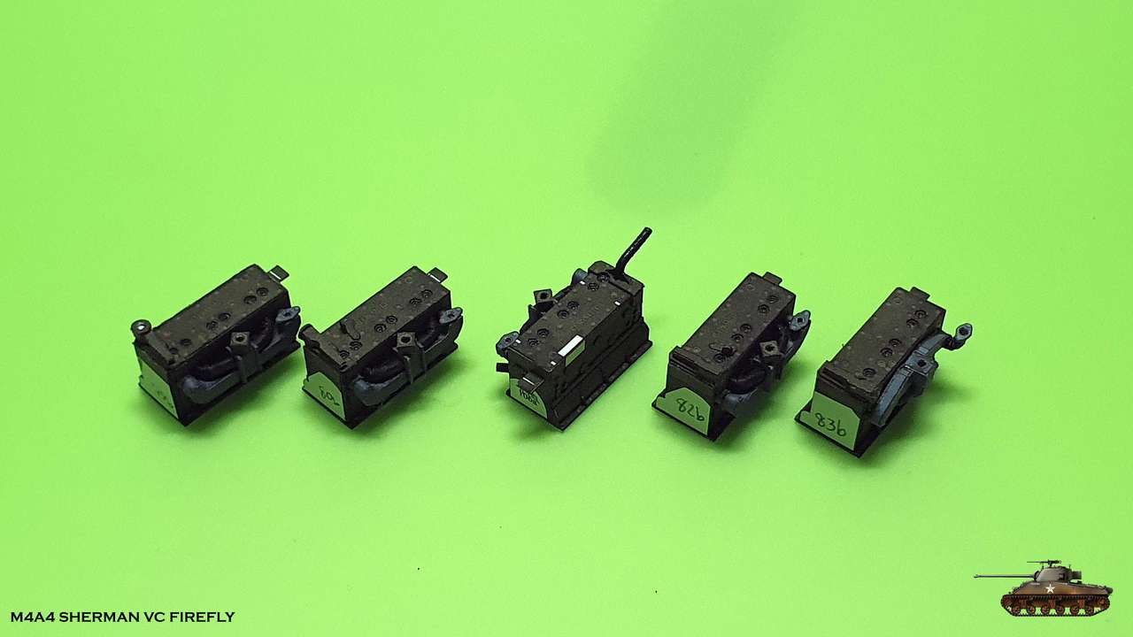
The next stage is the assembly of 5 engine blocks, when each block is a six-row car engine with 110-120 horsepower
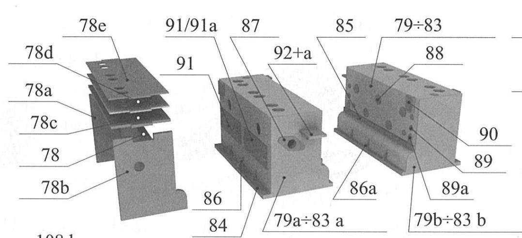
I collected all the necessary parts, laminated what I needed with cardboard and began to assemble
There is also a supporting structure, on which the casing will be glued. I decided to divide casing into parts.
This made it more convenient placement.
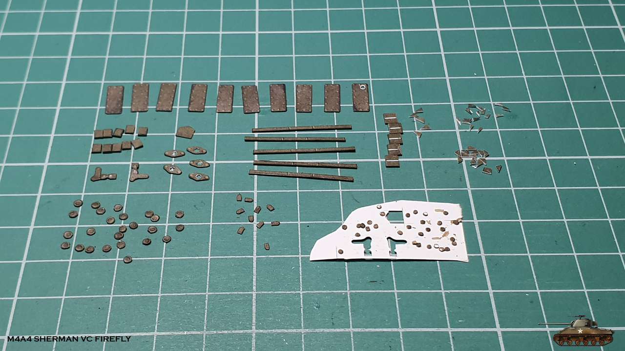
Plug holes are obtained by gluing several layers together with holes of different diameters.
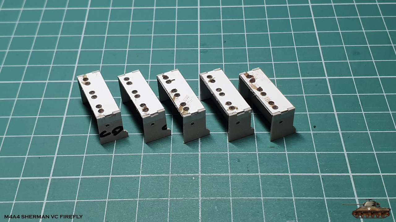
The casing is divided aside, and I cut out all the extra parts that are glued to the block.
The smallest bolts and rivets do not have to be glued, as there is an excellent pseudo print,
but for the sake of sport - I glued everything.
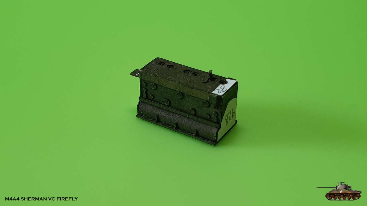
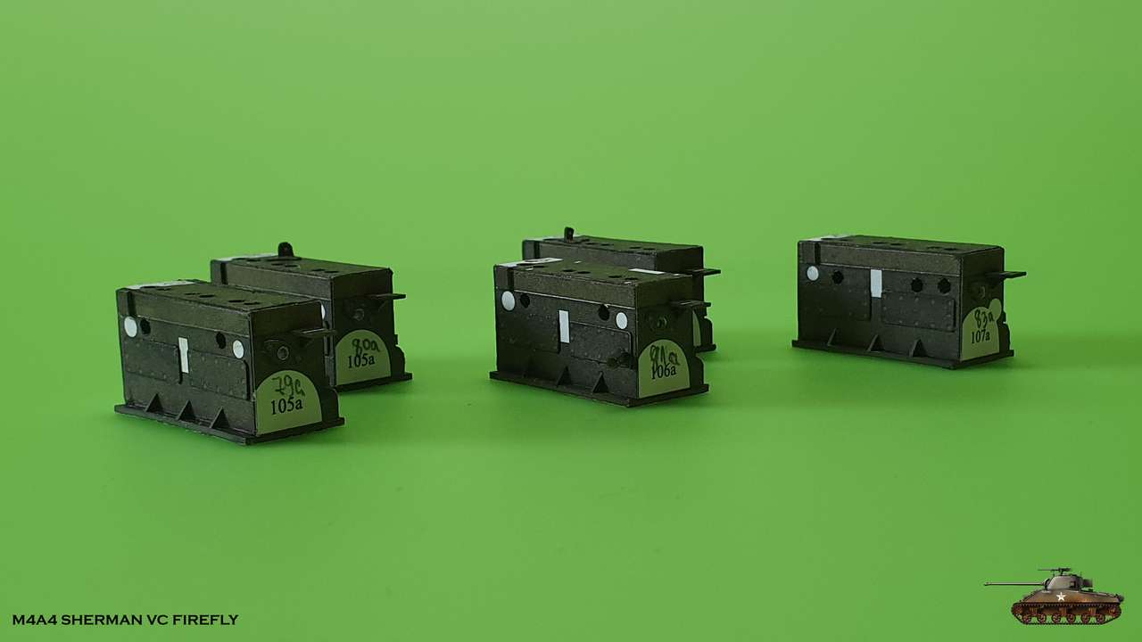
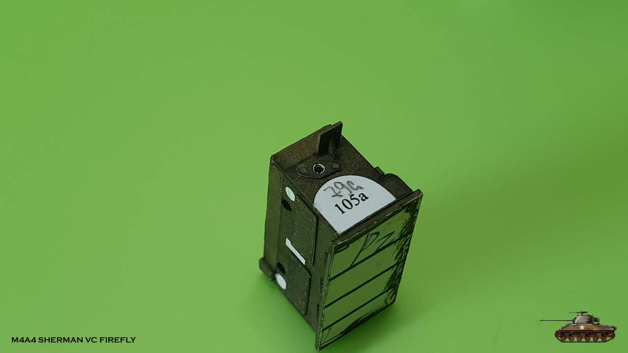
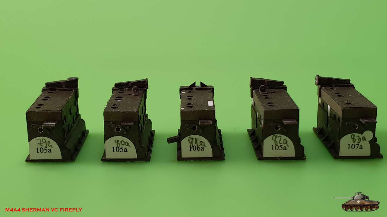
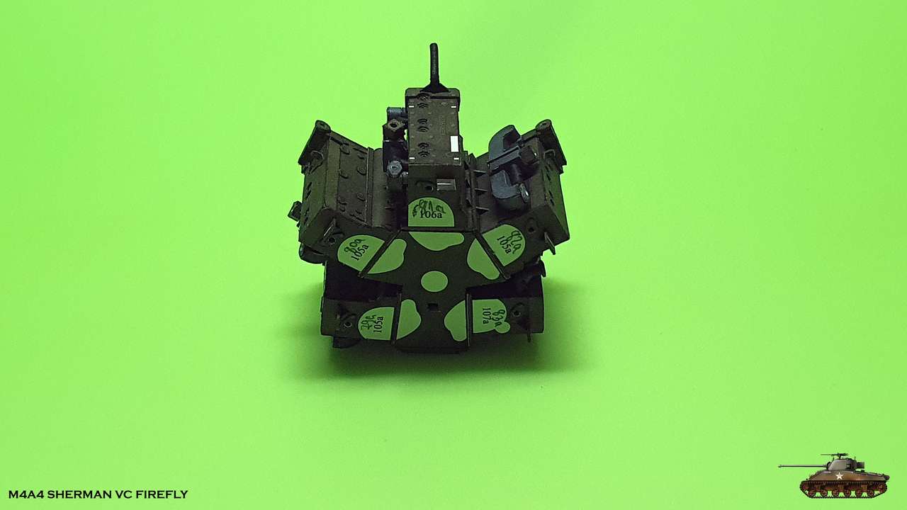
Please note - each unit is special and not like the other, because they are located at different angles and are connected in different ways to all hoses and tubes.
Therefore, it should be marked, in order not to confuse the details.

I collected all the necessary parts, laminated what I needed with cardboard and began to assemble
There is also a supporting structure, on which the casing will be glued. I decided to divide casing into parts.
This made it more convenient placement.
Plug holes are obtained by gluing several layers together with holes of different diameters.
The casing is divided aside, and I cut out all the extra parts that are glued to the block.
The smallest bolts and rivets do not have to be glued, as there is an excellent pseudo print,
but for the sake of sport - I glued everything.
Please note - each unit is special and not like the other, because they are located at different angles and are connected in different ways to all hoses and tubes.
Therefore, it should be marked, in order not to confuse the details.
А little progress
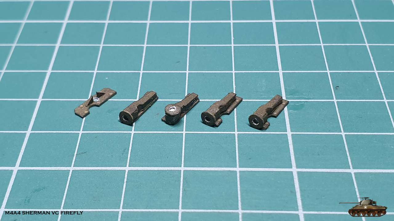
I installed 5 adapters connecting the radiator tubes to the engine and glued them on the blocks
Here too, each adapter is different due to the different angles at which each unit is attached.
Engineers worked hard and found creative solutions in the assembly of this monster engine")
I had to glue all adapters parts edge with edge with unusual angles,
But this is probably because lamination is not suitable due to the inclined angle of the adapter itself.

Also I found very interesting page with details about Chrysler A57 multibank
Enjoy!
Chrysler A57 Multibank Tank Engine
I installed 5 adapters connecting the radiator tubes to the engine and glued them on the blocks
Here too, each adapter is different due to the different angles at which each unit is attached.
Engineers worked hard and found creative solutions in the assembly of this monster engine
I had to glue all adapters parts edge with edge with unusual angles,
But this is probably because lamination is not suitable due to the inclined angle of the adapter itself.
Also I found very interesting page with details about Chrysler A57 multibank
Enjoy!
Chrysler A57 Multibank Tank Engine
Last edited:
So, after a week-long break, I returned to the model, and progress is already visible!
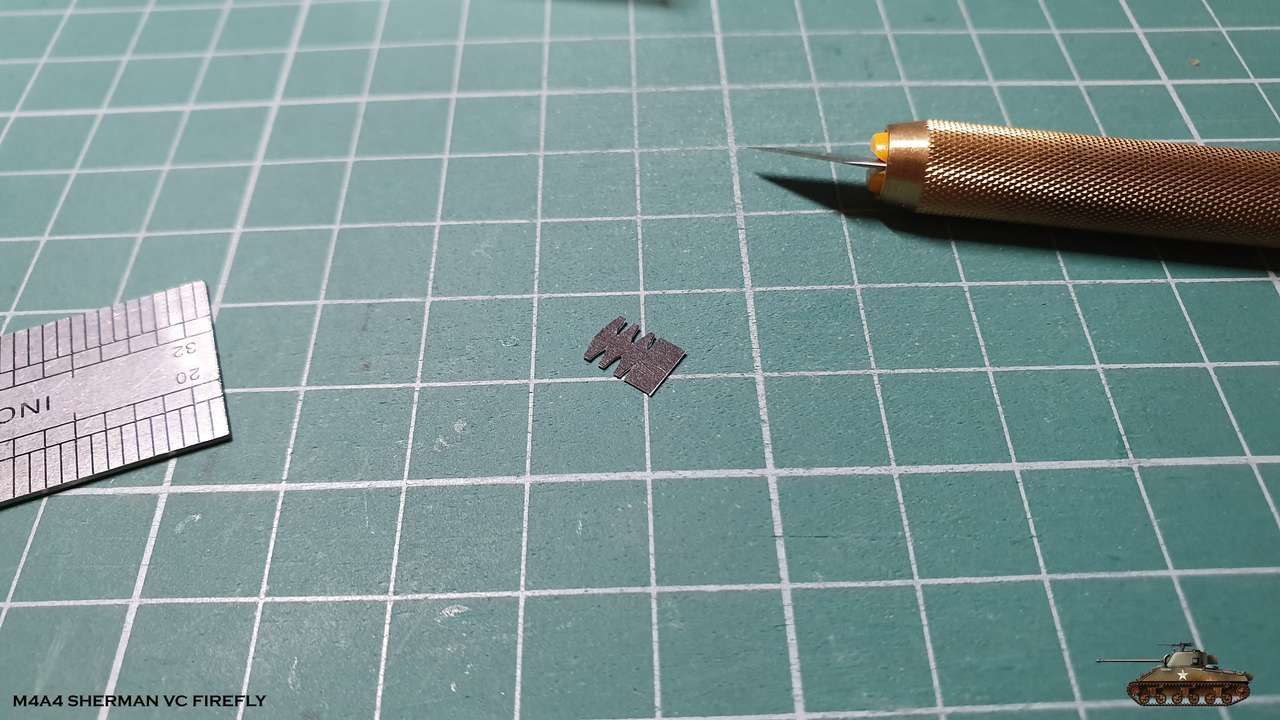
I began to assemble exhaust manifolds. It is also full of small details.

Everything is glued edge to edge at unusual angles.
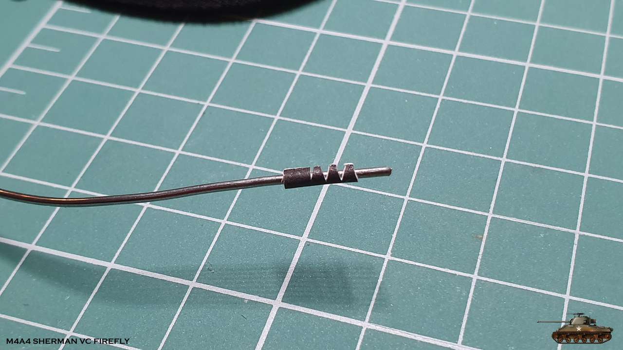
But the challenge was to assemble the curved tubes.
As a rule, it is possible to form them out of paper or bend them from wire.
I decided to form from paper, because I wanted to experiment a little.
In the future I will have to assemble large exhaust pipes with crazy angles and I had to train on cats
At first I tried to cut out the whole part without reeds and stick it into the tube.
Next, cut the corners and glue bented. Although gluing the tube was easy,
cutting corners was uncomfortable even with the sharpest knife.
I tried the second method: cut out the entire part, including the reeds. Although it was necessary to glue the tube on the reeds - it turned out cleaner and easier.
I assembled in this method the remaining tubes. And of course the exhaust manifolds
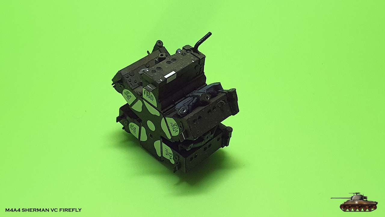
Glued them to the blocks. There is also a difference between the units, and the last one is different.

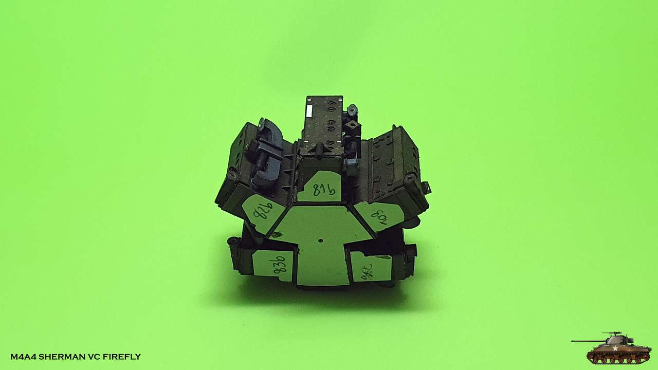
And here is the most interesting part! The blocks are assembled on the basis of the main crankcase and the outlines of the engine have already appeared!
I began to assemble exhaust manifolds. It is also full of small details.
Everything is glued edge to edge at unusual angles.
But the challenge was to assemble the curved tubes.
As a rule, it is possible to form them out of paper or bend them from wire.
I decided to form from paper, because I wanted to experiment a little.
In the future I will have to assemble large exhaust pipes with crazy angles and I had to train on cats
At first I tried to cut out the whole part without reeds and stick it into the tube.
Next, cut the corners and glue bented. Although gluing the tube was easy,
cutting corners was uncomfortable even with the sharpest knife.
I tried the second method: cut out the entire part, including the reeds. Although it was necessary to glue the tube on the reeds - it turned out cleaner and easier.
I assembled in this method the remaining tubes. And of course the exhaust manifolds
Glued them to the blocks. There is also a difference between the units, and the last one is different.
And here is the most interesting part! The blocks are assembled on the basis of the main crankcase and the outlines of the engine have already appeared!
Last edited: