Alien(s) Narcissus by DanBKing

DanBKing

Dan the Man
Feb 29, 2012
1,914
1,905
113
Netherlands
So, here we go.....

Back in 2010 or so, I attended an Amsterdam Comic-Con, where I had the great pleasure of meeting the renowned modeller - Lee Stringer.
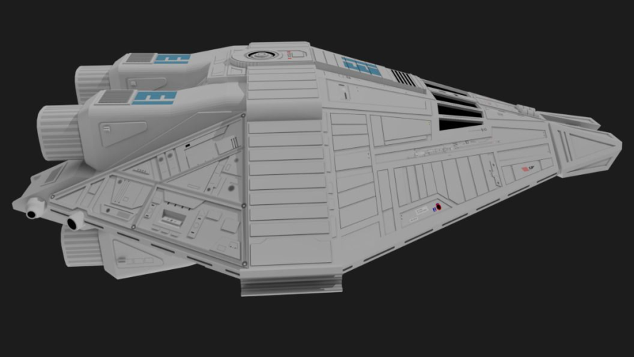
He had on display, his nearly complete, fully accurate model of the escape shuttle NARCISSUS, from the 1979 Ridley Scott film ~ ALIEN.

I was blown away by the detail!


Well, a few months ago, while trawling the net, I came across this......(Which is also available in the Resource Section!)


And you know what?
I decided it had to be done!

Let us enjoy the journey....

Ripley survived for 57 years in that ship!
Let's hope I finish the model within that time span, as I'm sure most of us do not have a stasis capsule available......;)


There are a few points that potential builders of this model should be aware of .......
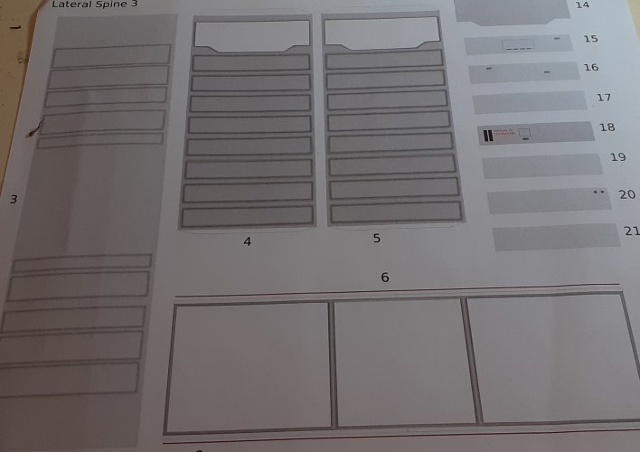
  • I printed the template on 250 gsm stock, and purchased 2 sheets of A1 size, 0,5mm thick stock for laminating parts.
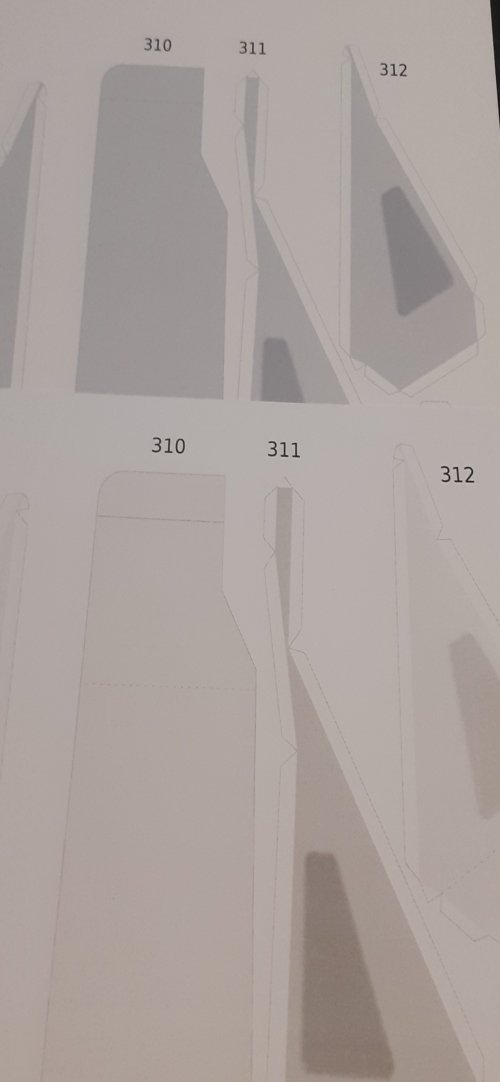
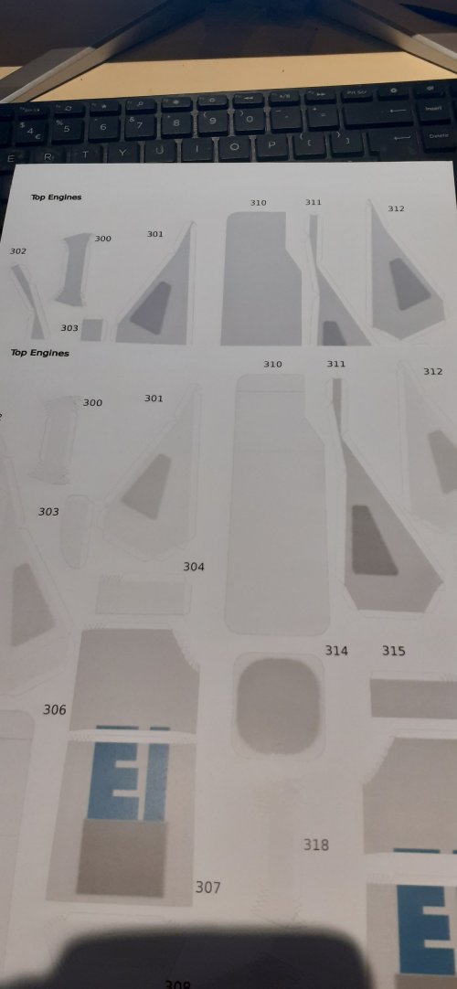
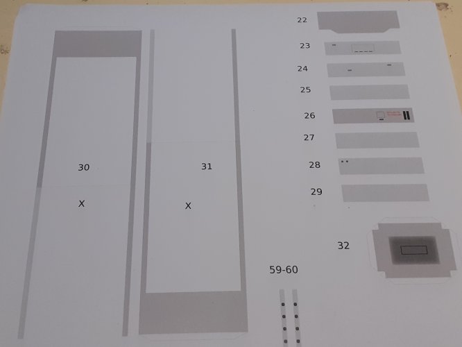
  • I had a lot of problems, (and expense,) to get the template printed correctly. It took 4 attempts, by 3 different printing companies to get it right. I think there is something wrong with the pdf file itself. As an example, I printed the pdf twice, one after the other, on the same printer, and I was getting different colour shading on different parts, even though the source file had exactly the same shading values. I tried 'printing to pdf', converting to jpg', but to no avail. The problem remained. Even if I printed the file again, the same problem occurred, but, on different pages! It was a very frustrating experience! As shown below, all the parts should have an identical colour shade......

20241213_235228.jpg20241213_235124.jpg20241213_234552.jpg20241213_234534.jpg20241213_234310.jpg

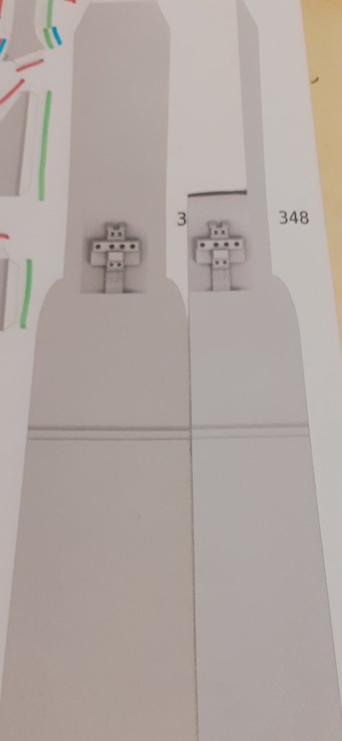
  • When you eventually get the print formatting correct, make sure that you print 2 copies of page 43. The copy of 43 you'll need, as you have to make the same part twice!
  • Make sure you have a good stock of blades for your cutting tools, this model involves a LOT of cutting out! Various blades I recommend: #11 X-acto blades (I used around 15!), Scalpel blades, chisel type blades and break-off-blades.
  • A glue roller, is a good idea, as I'll explain later....
  • This model is designed to very fine tolerances. If you mess up a cut, it will screw things up later on in the build! On some parts, the edge looks straight, but on closer inspection, it has two angled planes. Be aware of this, especially on the engines.
  • This is a BIG model! Structural support is highly recommended! Because gravity is a downward drag in this hobby!
The first thing I did was to go through the instructions and identify which parts need to be laminated to 0.5mm. It is at least 60% of the parts! I coloured the part numbers on the template sheets and eventually roughly cut out around all the marked parts, and using spray glue, laminated them to the 0,5mm card. The sheets were then placed between two sheets of foam board and compressed under my toolbox, (around 45kg,) for a day.

Let's put this beauty together!

orig.png

See you all soon! :wave:
 
Last edited:
I witnessed the development of this kit a few years ago!!! It is the best Narcissus paper model out there. However I may remember noticing that there are some decals missing. You should take Lee's build thread of his replica as a base to see if something needs to be updated:


I too know this printing issue. It happened to me with the firehouse roof. The pages were created with the same program, the same settings, and were printed with the same paper, printer and ink. Sometimes they came out correctly with vibrant colors, something they looked foggy and desaturated. Still no idea what's causing it and how to solve it.
 
I witnessed the development of this kit a few years ago!!! It is the best Narcissus paper model out there. However I may remember noticing that there are some decals missing. You should take Lee's build thread of his replica as a base to see if something needs to be updated:
Yes, I noticed that too.
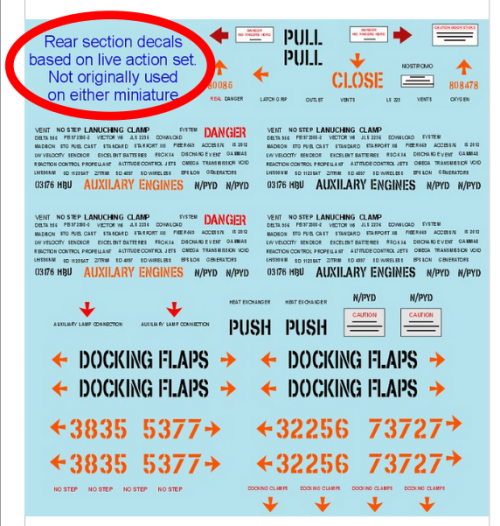
However, as Lee noted in his blog, some decals were only used on the live set, and not on the models themselves.
Maybe David Lukens excluded these purposely, as most of the decals missing on the model are mainly the ones noted by Lee below.

1734182504011.png
 
"I bought a mirror to Lovers' Lane. I told everybody I'm Narcissus!" ~ Steven Wright.


I am building this model, pretty much out-of-the-box, and followed the designers instructions... Well, not always!

The first part of the model is the lateral spine.
This part is key to the integrity of the model as a whole. Everything else hangs from it!!!
As I mentioned earlier, the tolerances of this model are very fine, and accurate cutting and alignment of parts is very important.

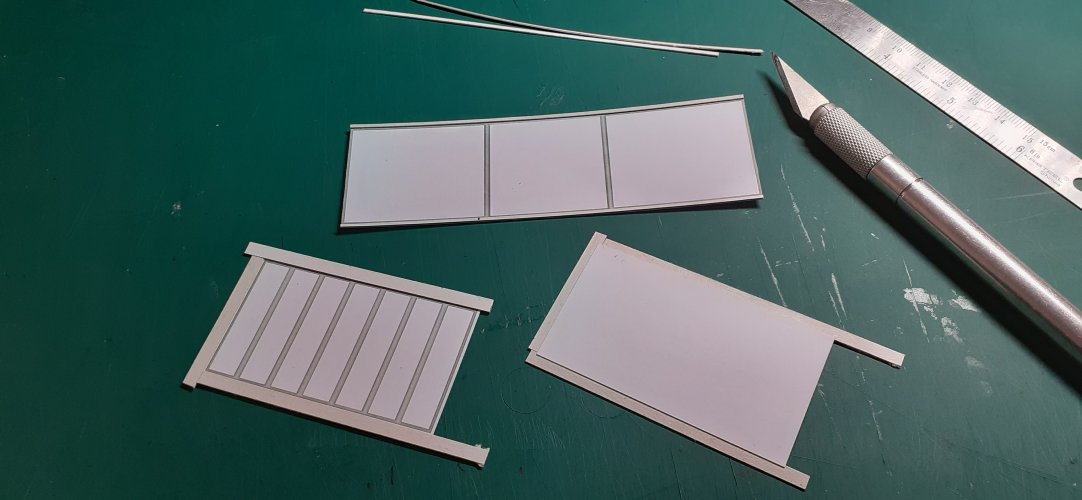
I cut out parts 6, 9 & 10.
These parts need their edges built up to 0.5mm thick. The instructions suggest making 1mm strips and attaching them.
I found it easier, and the result more linear true, to cut the strips wider than 1mm, glue them on and trim them to size once dried. Even though the strips will be oversize, once you turn the parts over, and trim the strips from the bottom using the part edge as a guide, the result is more accurate and straight overall.

1.jpg

The instructions show to add all the detail pieces at this stage.
I waited for that.

The attachment of parts 30 & 31 is not easy! We are talking about a gluing surface of 1mm wide and almost 25 cm long, in total, on BOTH sides!!
Again, accuracy and structural strength, is paramount here, and I'll explain why in a bit....

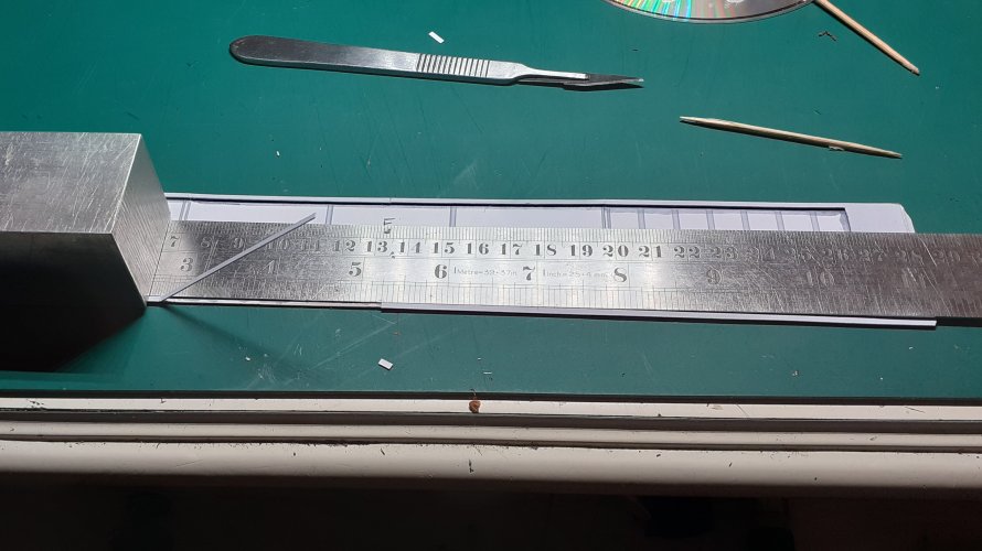
Once all the built up edges were trimmed, I temporarily taped parts 6, 9 & 10 together, and using a steel rule as a guide, glued the larger end pieces of 30 & 31 to these first, and then the thin edges. Again, I cannot stress enough; ACCURACY!

2.jpg

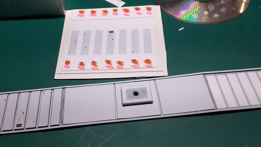
Now I added the detail panels that I had earlier laminated to required thickness. I suggest using card spacers along the edges while gluing them, to keep all the panels aligned and true.
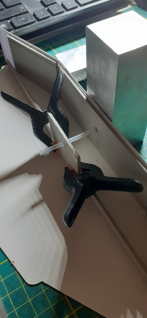
Part 32, I cut out and wrapped around various thicknesses of laminated card to make a solid card block structure. I then drilled a small hole through the middle of it....

I added thick pieces of card to the backs of parts 6, 9 & 10 for structural support.
I then drilled through the reinforcing piece of part 6, using the hole from part 32 as reference.

3.jpg


Parts 1 & 2, already laminated to 0.5mm, were cut out. Keep the cut on the line!!!!!
I added an internal strengthening cross-bar of thick card, to keep them flat.

And then the fun began...!

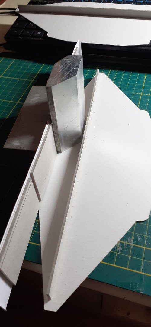
I laid part 1, (or 2, doesn't matter,) on a flat surface and glued one edge of the center section, of the previous assembly to it. I used machined blocks, set-squares, etc to keep everything square and aligned. Test your centering of the piece, by making sure the end flaps of parts 30 & 31 fit snug against the ends of 1 & 2!

Measure 20 times, glue once!

4.jpg

From the photo above, you can also see how thin the gluing edges are to parts 1 & 2.... 1,5mm wide max!

I then glued the edges of the sloping panels to part 1, and let dry

The hole I drilled earlier, now comes into play!
This will be the mounting point for the display stand.
I used the same process as I did with my 2001 Orion model a few years ago.
I use a steel rod, as the model support. The rod I have fits snugly and conveniently into an ink tube of a (dry) ball-point pen.
This combination allows me to insert and remove the model from the stand as required.
Works pretty much the same way as they do it in the movie industry.....

I fitted the tube, added some thick card bracing pieces and then fixed everything solidly together with hot-glue gussets.


5.jpg


More soon! :wave:
 
"Mistakes - call them unexpected learning experiences." ~ Richard Bach

Following on from the last post.....

The other side piece, part 2 (or 1,) was added to the previous assembly in a similar manner.
Once this was dry, I cut out parts 3, 4 & 5 and reinforced them with thick card. Remember to pre-form the two curved sections of part 3 before assembly.
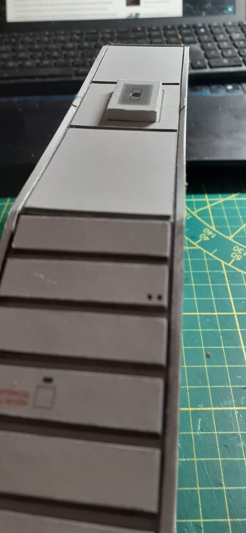
These panels were then glued to the top of the lateral spine, as per the instructions, and the laminated detail pieces were then added.
The lateral spine is now complete, and you should now have a very sturdy box shape.

It was at this point that I noticed my first boo boo!

I'm not quite sure how it happened, but I think I applied a little too much pressure when gluing the tube construction for the display stand.
The biggest bummer is that I did not notice the mistake until I had already closed up and completed the lateral spine, therefore I could not rectify it.
The edges of the bottom panel assembly had pulled down giving it a concave indent. :(

6.jpg

Because of all the problems I had with printing the model with the correct colouring previously, I very much doubt I would get an accurate colour match again, if I reprinted the lateral spine parts to rebuild it.
In hindsight, I should of printed two copies of the model, but as they say, 'Hindsight is a b***h!'
But, I think I can get away with it, as a good portion of those deformed panels will be covered by other parts later on.

Because I cannot reprint, I cannot afford to make any more mistakes!
Let's add some tension to the build, shall we ?!!? :sticktongue:


Putting the lateral spine out of sight, and therefore out of mind, I started the next part of the build; the center panel for the lower forward hull.


This is the point where I went on a slightly different route than the instructions.....

Reading through the instructions before the actual build, I noticed that there were a lot of requirements to build up edges/faces/thin rails, etc to create the recessed panel look on a lot of parts.
Using this method, it was suggested that all the raised edges/faces/thin rails, etc, be built up using 0.5mm thick strips, at +/- 1mm width. The inset panel itself should be built up this way and then the upper detail panel was cut out and glued on top of this.
That did not seem the most productive way to me.. the amount of cutting, gluing, trimming required would be a time (and patience) killer.
I'm trying a different approach...

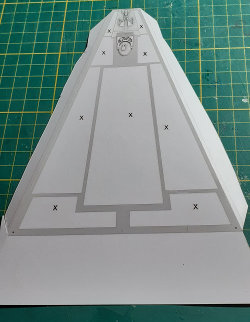
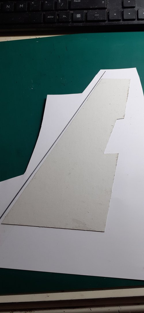
I roughly cut out part 166 and scored and folded the long tabs down each side of the piece...

A piece of 0,5mm thick card was cut to shape and glued to the back of the part, using the fold lines as a centering tool to ensure alignment...

7.jpg8.jpg

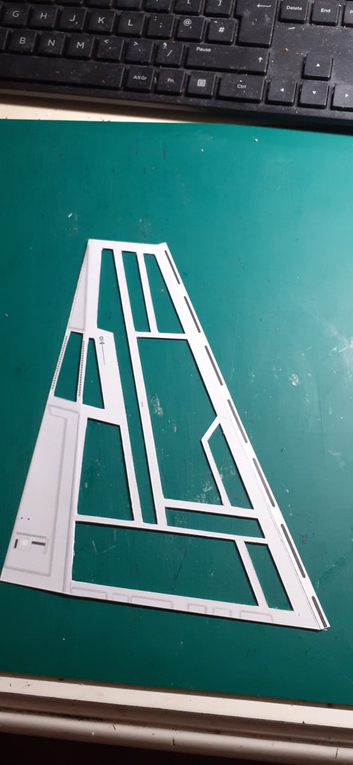
Once the glue had dried, I cut out all the 'X's as indicated, (but, see note below...) This left me with a frame, already thickened, which then only required gluing to the recess panel conglomeration (on page 'Front Hull 7'.)
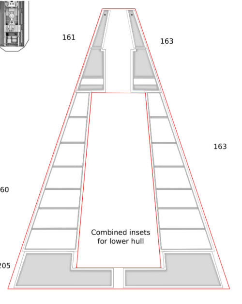
I cut out the recess panel, as outlined in red in the graphic below.

Screenshot from 2024-12-19 13-57-58.png
A quick note here; I think it would be better to cut out the large rectangle where the 'engine bay' is to be located, only after gluing the recess panel on. Then there is a better chance of keeping everything square and aligned when cutting through.

Next up, the detailing of the panel with the pre-laminated pieces......
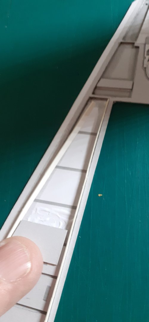
I used two strips of card to keep everything aligned when gluing the side detail parts on.

9.jpg

Once these were done, (which is a very tame version of what is to come,;):cool:) I made up the engine bay frame.

10.jpg

The detail parts for the engine bay were made next.
I cut off all the tabs of the parts for the side pieces of the T shape, which gave me a cleaner finish overall.
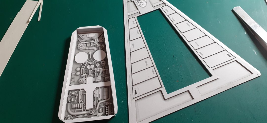
The engine bay assembly was then attached to the panel from behind.

11.jpeg

Stage 2 complete.....

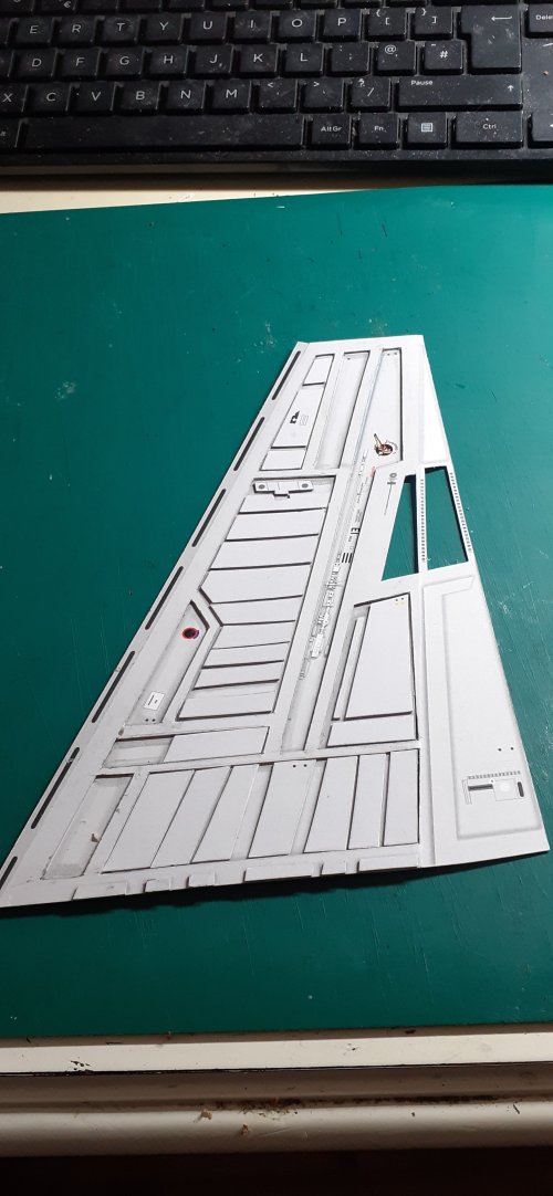
The two lower hull side panels were made up next. I built these together as a mirrored pair.

As suggested in the instructions, these panels do not require thickening, mainly because of the fineness required to cut out the detail frame. It could be done, I guess, but I didn't bother either!
Make sure to score and pre-fold the tabs along the long edge of each piece before doing any cutting!!
I cut out the frame sections, keeping the two sections together on the parts page, with plenty of excess card around them to keep rigidity while cutting.

12.jpg

The recess panels were laminated to cereal box type card and when dry, glued to the back of the pre-cut detail frame.
Once the glue had dried, these sub-assemblies were cut and trimmed to size..
And, the laminated detail parts were then added...

13.jpg


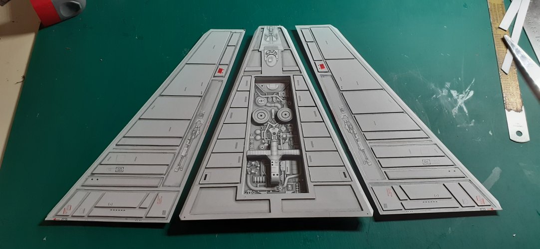
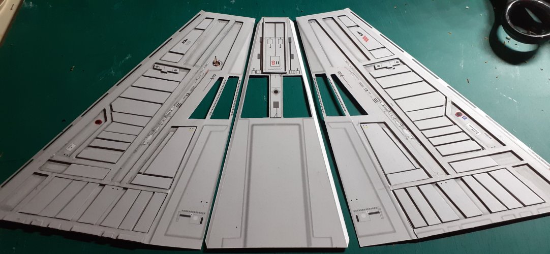
This then completed the construction of the lower front hull panels.

14.jpg


I have a few observations, suggestions, ideas and comments I would like to make over the build so far.
But, that will be the opening of the next post!

See y'all soon :wave:
 
Last edited:
Lateral distortion is a common problem with Weyland-Yutani ships. It happens regularly when the main airlock is opened in space to jettison junk and will even get worse if the Captain screams spectacularly before pressing the release button. The sound waves create vibrations which can get so strong that they affect the integrity of the main hull. To reduce the effect a special team of sound designers added a "safety sound" to the vessel which sounds like the fart of old Santa (seen and heard here). They were so proud of their creation that they put the slogan "In space no one can hear you scream" on each of their product.
 
Another masterpiece in the making. I knew you'd be back. It's mighty fierce out there, and that hunger just comes up on you.....................I just watched "The Yearling" with Gregory Peck"....

Seriously though, it's great to see one of your works happening here. :)

I'm Back.jpg
 
Another masterpiece in the making. I knew you'd be back. It's mighty fierce out there, and that hunger just comes up on you.....................I just watched "The Yearling" with Gregory Peck"....

Seriously though, it's great to see one of your works happening here. :)

View attachment 222355

Thank you, Z.
It feels good to be back!
I dunno if I've ever created a masterpiece though, but I'll keep trying! ;)
 
"For it is only framed in space that beauty blooms." ~ Anne Morrow Lindbergh


As I mentioned at the end of my last post, I have some insights I wish to make over the build so far.
This I will include as I continue with this part of the build, as having some relevant photos will aid in my explanations...!
  • Also, these insights/observation/ideas/etc, will be bulleted in this post, as like this one.... ;)

With the lower forward hull panels complete and ready for final assembly, I continued the build with the upper front hull panels...

I made these panels in unison, but I am only showing one side panel in the pics. The other panel is obviously mirrored, but constructed in the exact same way.

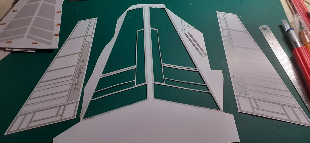
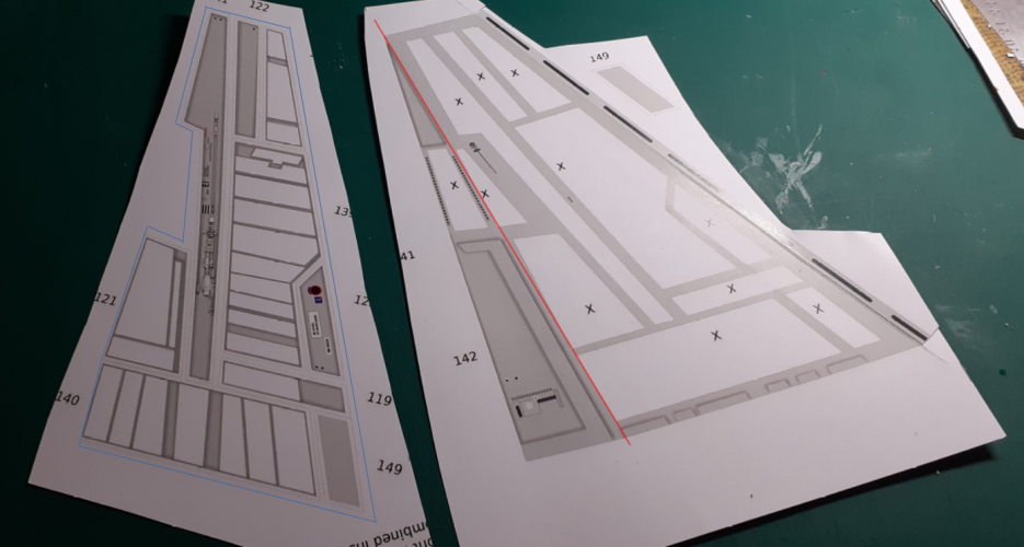
In the pic below, the part on the left is the sub-panel conglomeration, and on the right, the frame (or skin.)

15.png

The sub-panel(s), I laminated to cereal box type cardboard and placed it under my 'book press' until dry.
I then cut the laminated panel out, following the blue line, as shown in the pic above.
I left a good 3 mm white space around the part, which will give more gluing area later, for strength.
The only exception to this, is the lower left corner of the part, (next to the no's 121 & 140,) this needs to be cut exactly to the template, as you'll see why in a minute....

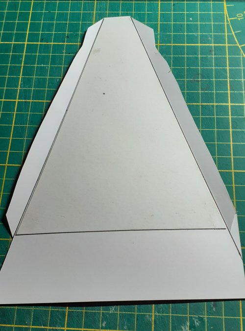
For the frame section, the long edge, (on the right in the pic,) which will eventually join to the lower hull panels, needs to be accurately scored and folded, prior to cutting anything out.

You will notice the red line over the part, in the pic. This is a fold line too, which I nearly missed! I recommend scoring this line from behind the part. The fold does not have to be a sharp fold, but it needs to be there. Also note how the fold line goes diagonally through the window frame, which is very thin, hence the need to pre-fold parts BEFORE cutting anything out!
  • Come to think about it, follow this rule throughout the whole model !!!!!!!
I used the laminated sub-panel assembly as a template and cut out a piece of 0.5 mm thick card to match.
This I then glued/laminated to the back of the frame, where the sub-panel will go. Shining a light through the back of the part as you place it, will help line it all up, especially the edge, (as mentioned above when cutting the sub-panel out!)
This was then put in the book press for an hour or two.

16.jpg

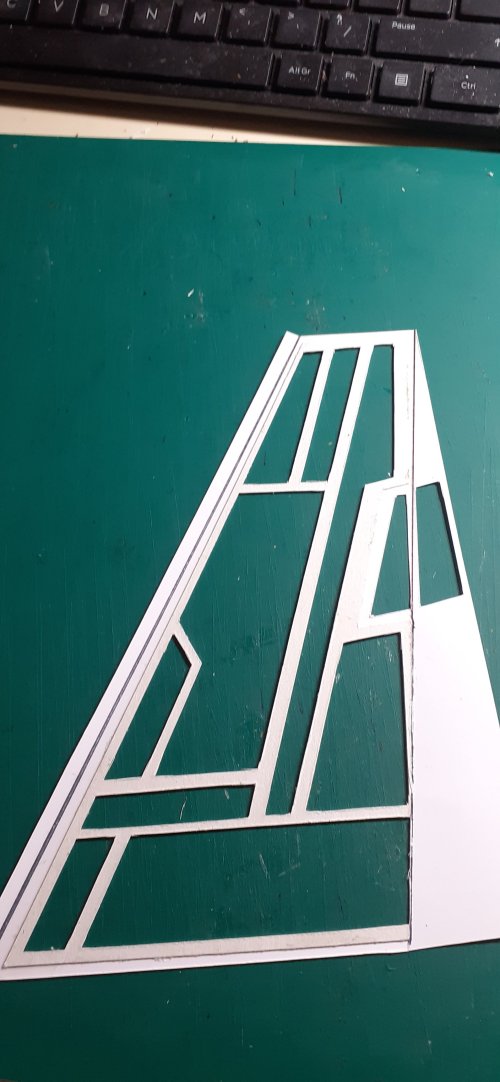
Once dry, the frame parts were cut out.
In the second pic below, you can see the result of the cutting out, as seen from the back of the part. Note the edge of the lamination, at the important point, as outlined earlier, (bottom right of the pic.)

17.jpg18.jpg

All the edges and corners of the cutouts were cleaned and tidied up. A bullet coming....
  • I edge-coloured all the cut parts with an ink pen, where necessary, that matched the surface colour. It is a time consuming process, but worth it in the end. Be careful with thin parts when you do this.

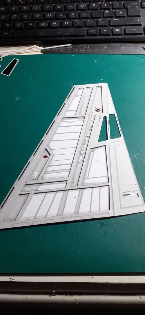
The frame was then glued to the sub-panel assembly, making sure everything is lined up perfectly.

19.jpg


And, guess what?... It is bullet time!!!!!!

  • I made the choice to use a glue-stick to glue the raised sections of the frame to the sub-panel. My reasoning for this, was that I wanted a glue that I could quickly apply to the back of the (raised) frame in one go, and not having the glue dry out on me before I get to attach it to the sub-panel. Also, I did not want a glue that has a instant bond, because a lot of adjustments need to be made before the glue dries. But, a glue-stick is a messy puppy! Once I had attached the frame to the sub-panel, I had to quickly go around all the raised edges with a toothpick to clean up all the excess clumps of glue.
  • In hindsight, I would strongly recommend using a glue roller, with a less messy type of glue, for attaching the frame to the sub-panel! The result will be cleaner, with less mess and give a stronger bond than a glue-stick. Glue-stick glue becomes brittle when dry, and breaks away quite easily. Probably, a good layer of ordinary PVA/wood glue would work best in this instance.

Next up, the detailing......
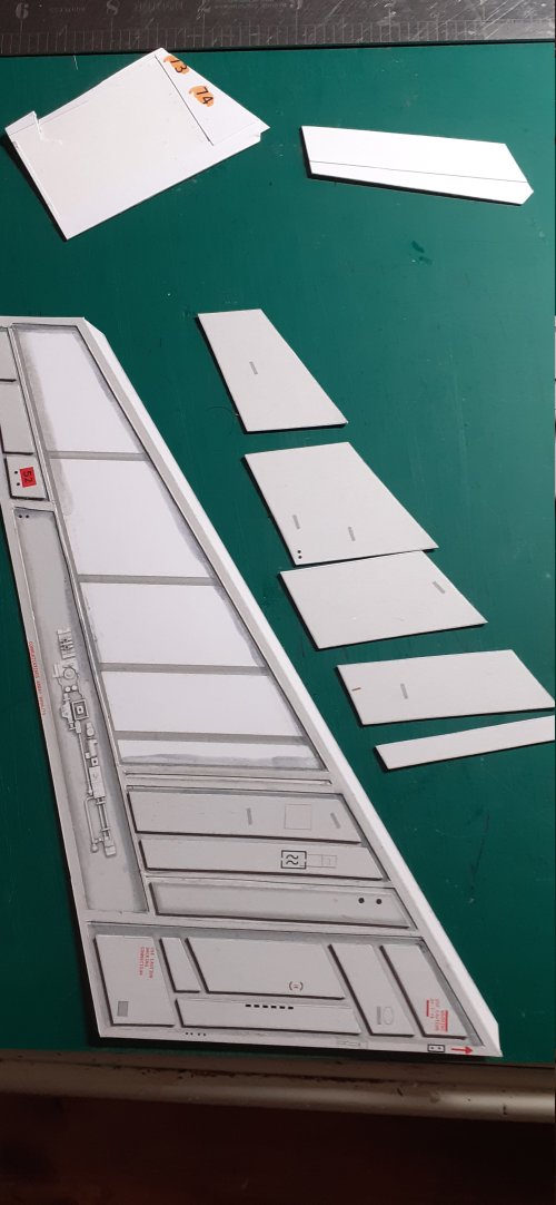
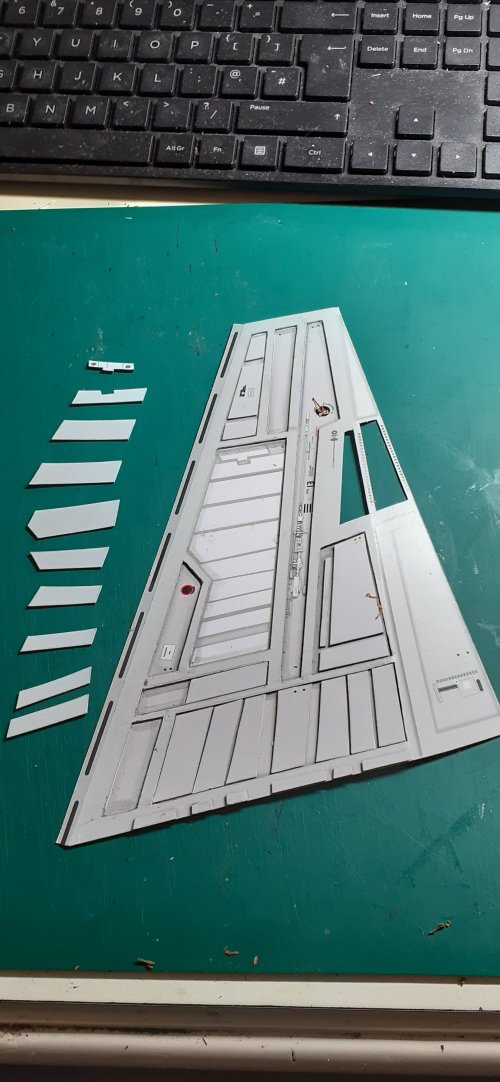
All the pre-laminated detail parts were cut out and edge-coloured and then applied one by one to their designated places...

In my next post, I will have a lot to say about this process, which will improve the template big time!

20.jpg21.jpg

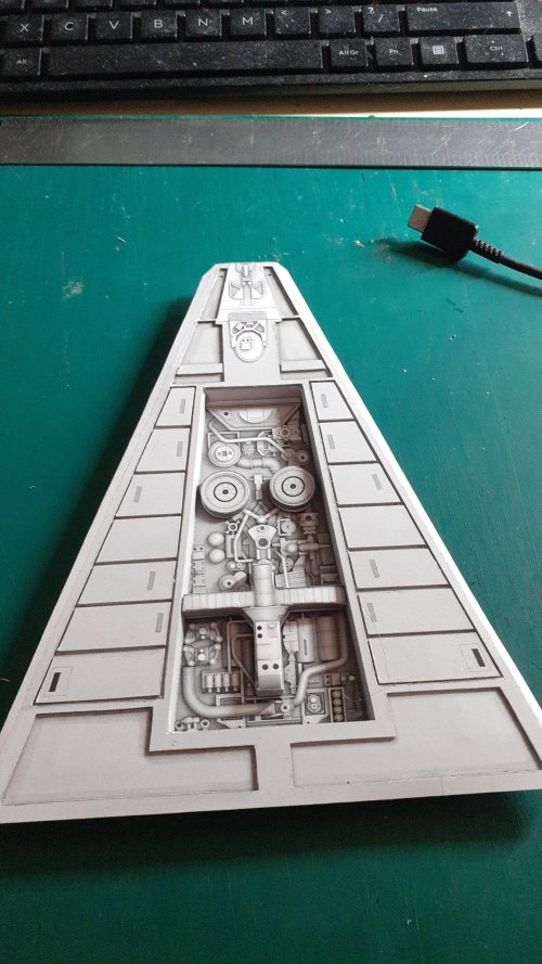
The center panel of the upper front hull is very straightforward.
Again, pre-fold the edges before cutting.

The rectangular part towards the nose of the model is made up of part 69 & 228.
I cut out the center of the rectangle of part 228 first, before cutting it out from the parts sheet and then aligned and glued part 69 behind it. Once dry, I cut around the outer perimeter of pt 228.
The resulting assembly was then glued to the nose end of the center panel. Part 232 was glued aft of this.

22.jpg

I'm satisfied(ish) with the build so far.

More soon! :wave:
 
Everything looks clean, clear, and crisp!
I really like the in-depth explanation of what you are doing (and why). This is something that I find really helpful (especially since I have never built this model before).
I am really looking forward to seeing how this project turns out!
 
  • Like
Reactions: DanBKing
I admire your modesty, but your work speaks volumes, it it's all good, and demonstrate a mastery and deep understanding of what you are doing, and they are masterpieces. ;)