2OO1 ASO Station V

DanBKing

Dan the Man
WARNING!! This post contains images that sensitive viewers may find offensive! Proceed at your own risk!


Next up, the main ring....

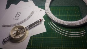
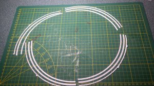
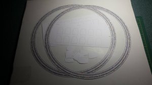
The first side was laid out and glued together on a piece of foamboard. I used a pin at the center point to keep everything aligned.

The positioning lines need to be added to the back. Simply make pin holes through the card at the outer radius of the ring, lining up with the guide lines. Turn the template over and again using a pin at the center point, draw the lines. The pin helps keep your ruler at the center point, therefore, you only need to concentrate on lining up one hole... ;) I also used a hard leaded pencil (4H) to draw the lines. My logic for this, is that the formers are edge glued directly to this positioning line, and I did not want any 'dusty' lead residue left over, from a softer pencil, which would weaken the glue joint. Probably over thinking it, but, anyway .....
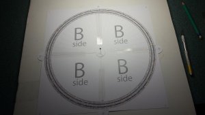
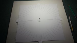
46.jpg 47.jpg

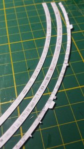
I pre-cut all the notches and protrusions around the ring and then did the main cutting with curved scissors.

The other side of the ring was also completed as above.
48.jpg

The formers are cut out next. These need to be cut accurately. Having the formers arrayed on the template, helps enormously with this.
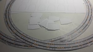
49.jpg

The work was then transferred onto the back of a float glass mirror tile. This provided a perfectly flat surface to work on.
I used the back surface of the mirror, because I did not want to have to look up my own nose the whole time during the assembly process.... :eek::biggrin:

I used two machined aluminum blocks to aid in assembly. One across the tangent of the outer circumference of the ring to keep the top edge of the former perfectly aligned with the outer edge of the ring. This is important to prevent waviness later on. The second block was used square to the first. This kept the former perfectly upright and aligned with the radii.
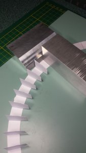
50.jpg

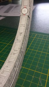
I used Aleens quick dry tacky glue for this. I used a bead of glue on the edge to be glued and using tweezers, dropped it into position. Use enough glue so that the edge beds in nicely, but not too much to cause the ring to warp from the moisture in the glue.
It's a tedious process, but you get there in the end. It is a lot quicker than assembling the UCR though! ;)
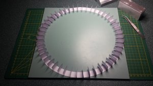
51.jpg

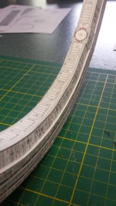
Once this stage of assembly was perfectly dry, I then glued the other ring face to this. I used the tangent block again to line everything up while assembling.
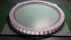
52.jpg


I remember clearly, the chain of events, that happened next...............


About a week later from the last picture, I was clearing up my work area and when I stacked together the off-cuts from the rings assembly templates, I noticed something very odd.......

The template off-cut for the UCR was 1 cm less in radius than the main ring template......... WTF??
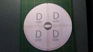
60.jpg


With a very strong sinking feeling in my soul, I laid the completed UCR on top of the main ring assembly.............
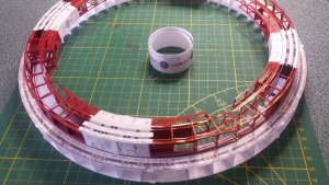


61.jpg


I thought that maybe it is meant to be like that..........


Using a test made center ring and the test spoke assembly from earlier, and with shaky hands, I proved that 'meant to be like that', was not the case......... :sadno:
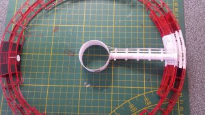


62.jpg


The F*&@$%# UCR was under-scale to the rest of the model......... AAAAAARRRRGGHH !!!!!!!!!! :headbange::headbange::headbange::headbange::headbange::headbange::headbange:

Something had gone seriously wrong at the printers.........


Oh, what to do................


WARNING!! Sensitive viewers may wish to look away now....


What should I do.........................


I NEED to make a decision.................


63.jpg64.jpg65.jpg


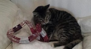
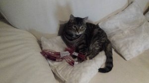
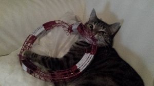
At least the space cat had some great fun............


See you all soon. :wave:
 

mijob

Tie designer
Staff member
Moderator
Nonono the worst nightmare for any papercarfter.
So sorry to see that this has happend with your project.
O well the cat had indeed some fun. Still its a verry strong paper assembly
 

Revell-Fan

Co-Administrator
Staff member
Administrator
Moderator
Oh my! I'm sorry!

1616347321911.png

However, this proves it's always handy to have a cat at home.

UNLESS -

Well the cat jumped into a model once... Perhaps it knew what would happen... Perhaps it was the cat that manipulated the printer to get a new chew-chew ...

1616347438895.png

OR WORSE: ALEENS!!! Here, you said it yourself:

I used Aleens quick dry tacky glue for this.

:hammerhead: :hammerhead: :hammerhead:
 
Last edited:

zathros

*****SENIOR ADMINISTRATOR*****
Staff member
Administrator
Moderator
That cats looks like it's related the my recently passed (seems that way) cat, who destroyed many models, and actually knocked them off the shelf for the dog to get! :))
 

Gearz

Member
NNNnnnnnooooooooooooooooooooo!!!!! Such a superb crisp build of a beautiful model. I was so happy until I clicked page two…. Sympathy Dan... :toast:


Is it to soon to say please start again..?
 

micahrogers

Moderator "Where am I, and how did I get here?"
Staff member
Moderator
Such an "in character" moment for the kitty, but at least it can be rebuilt... anyone for kitty stew...
 

DanBKing

Dan the Man
I contacted the printers about the problem of the under scale parts. He remembers printing them, because the parts for the UCR are printed on both sides of the template sheet, so that the cut out parts are red on both sides. He remembered struggling a bit to get them to line up properly. He agreed to print them again free of charge! So, I sent him the files again with good 'idiot-proof' instructions and awaited the delivery of the re-printed parts. He actually posted me 2 samples to check everything was correct! Very good service!

In the meantime, I carried on constructing the main ring.
I seem to have lost the photos of the actual construction of this, but it follows the same construction flow as that of the UCR. But, of course, a hell of a lot easier to build! :biggrin:

I cut out the detailing pieces for the sides of the main ring. I used a circle cutter to cut out most of the parts. However, the outer detail parts contain a lot of protrusions and recesses, these parts I cut out by hand.

72.jpg 73.jpg
74.jpg

These were carefully glued to the two faces of the main ring. They came out nicely and the ring faces have no waviness.

75.jpg


While I was doing this, I noticed an unsightly gap between the main ring and the inner ring which showed the inner formers. Unless I missed something, I could not find any parts in the templates to cover this, so I made my own. The strips needed are very thin, and I found the best way to cut these out evenly was to place two X-Acto blades together into the knife handle. The resulting gap between the blades was the same width as the required strip. Using a straight edge, I cut out various lengths of strip and glued them in place.
It finishes off the main ring very nicely!

71.jpg 70.jpg

So, with the main ring now completed and ready for mounting to the hub and spokes, I started the pre-assemblies for these parts.

Learning from the test build of the spoke assembly in the beginning of the thread, I modified my construction methods to increase accuracy.

There are many factors within the spoke and hub assemblies that require a high degree of accuracy when assembling.
The spokes need to be straight and perfectly round. The spokes take the stresses of mounting the ring and hub together, plus, the spokes need to have the suspension cable systems accurately mounted as well.

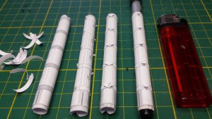
The spokes themselves are about 10mm in diameter. When I cut out the part, I left about 10mm of white-space on one of the long edges. This white space allows you to start the curving process without damaging or wrinkling the actual part. I used a 8mm dowel rod to form the tube. Start the forming process from the white space side and roll the part tightly to the dowel. Once the tube is formed, I cut off the white space with scissors. The resulting strip then provides you with a pre-shaped back tab to glue the tube together. Glue one side of the tab first and then when dry, carefully glue the tube together keeping everything aligned. Because the preformed tube is slightly undersized, the two joint edges tend to spring together on their own, aiding the gluing process. Use a dowel to allow back pressure for pressing the joints edges down.

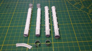
The mounting brackets for the cable assemblies were added next. In the test build, I mounted these by first gluing one of the cable assembly mounting points together, and when dry, attaching the brackets to the spoke in one go. But, I didn't get the accuracy I was looking for by doing it this way. As you can see in the pic below, in the middle of each bracket piece there is a small rectangle printed as texture. This rectangle lines up perfectly with the texture on the spoke. I used this reference and glued each bracket piece to the spoke, but leaving the ends unglued at this stage. I then glued up both ends and using tweezers, crimped the edges together on the center line marked on the spoke. I found a pen that fitted snugly inside the tube, that helped in assembly giving nice back pressure to press the brackets on firmly.

A tab, to aid the attachment of the end cones were glued in now too. The pic shows the process.

66.jpg

The end cones were added next, making sure to keep the joints aligned. The inner cones have a slight wave shape when cutting out, to accommodate the curve of the hub.

67.jpg

I started up the sub assemblies for the hubs too, that will all be revealed in my next build post.

See ya! :wave:
 

Revell-Fan

Co-Administrator
Staff member
Administrator
Moderator
Fantastic progress! Great to hear that the printing issues were sorted out. I agree, this is the way to guarantee customer satisfaction. thumbsup
 

Rhaven Blaack

!!!THE MAN BEHIND THE CURTAIN!!!
Staff member
Administrator
Moderator
Your work on this project is TOP NOTCH! Everything looks clean, clear and crisp! I am glad to hear that the printing company reprinted everything for free.
I am really looking forward to seeing how this turns out!
 

zathros

*****SENIOR ADMINISTRATOR*****
Staff member
Administrator
Moderator
Great progress. I'll bet seeing how you made the first only, you've found that making the second one is just as hard, if not harder, with an intense sense of deja vu! :)
 

Chuffy70

Well-Known Member
WARNING!! This post contains images that sensitive viewers may find offensive! Proceed at your own risk!


Next up, the main ring....

The first side was laid out and glued together on a piece of foamboard. I used a pin at the center point to keep everything aligned.

The positioning lines need to be added to the back. Simply make pin holes through the card at the outer radius of the ring, lining up with the guide lines. Turn the template over and again using a pin at the center point, draw the lines. The pin helps keep your ruler at the center point, therefore, you only need to concentrate on lining up one hole... ;) I also used a hard leaded pencil (4H) to draw the lines. My logic for this, is that the formers are edge glued directly to this positioning line, and I did not want any 'dusty' lead residue left over, from a softer pencil, which would weaken the glue joint. Probably over thinking it, but, anyway .....


View attachment 193090 View attachment 193091

I pre-cut all the notches and protrusions around the ring and then did the main cutting with curved scissors.

The other side of the ring was also completed as above.

View attachment 193092

The formers are cut out next. These need to be cut accurately. Having the formers arrayed on the template, helps enormously with this.

View attachment 193093

The work was then transferred onto the back of a float glass mirror tile. This provided a perfectly flat surface to work on.
I used the back surface of the mirror, because I did not want to have to look up my own nose the whole time during the assembly process.... :eek::biggrin:

I used two machined aluminum blocks to aid in assembly. One across the tangent of the outer circumference of the ring to keep the top edge of the former perfectly aligned with the outer edge of the ring. This is important to prevent waviness later on. The second block was used square to the first. This kept the former perfectly upright and aligned with the radii.

View attachment 193094

I used Aleens quick dry tacky glue for this. I used a bead of glue on the edge to be glued and using tweezers, dropped it into position. Use enough glue so that the edge beds in nicely, but not too much to cause the ring to warp from the moisture in the glue.
It's a tedious process, but you get there in the end. It is a lot quicker than assembling the UCR though! ;)

View attachment 193095

Once this stage of assembly was perfectly dry, I then glued the other ring face to this. I used the tangent block again to line everything up while assembling.

View attachment 193096


I remember clearly, the chain of events, that happened next...............


About a week later from the last picture, I was clearing up my work area and when I stacked together the off-cuts from the rings assembly templates, I noticed something very odd.......

The template off-cut for the UCR was 1 cm less in radius than the main ring template......... WTF??

View attachment 193097


With a very strong sinking feeling in my soul, I laid the completed UCR on top of the main ring assembly.............


View attachment 193098


I thought that maybe it is meant to be like that..........


Using a test made center ring and the test spoke assembly from earlier, and with shaky hands, I proved that 'meant to be like that', was not the case......... :sadno:


View attachment 193099


The F*&@$%# UCR was under-scale to the rest of the model......... AAAAAARRRRGGHH !!!!!!!!!! :headbange::headbange::headbange::headbange::headbange::headbange::headbange:

Something had gone seriously wrong at the printers.........


Oh, what to do................


WARNING!! Sensitive viewers may wish to look away now....


What should I do.........................


I NEED to make a decision.................


View attachment 193100View attachment 193101View attachment 193102


At least the space cat had some great fun............


See you all soon. :wave:
For a minute there I thought you were going to put it down the end of the garden, as per the pic at the start of your build...lovely cat, what's it called? At least Aries turned up in 2015
 
Top