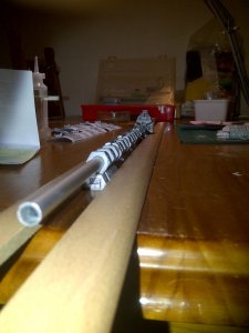
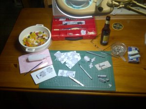
A moment of truth.....
Well, it has been one heck of a week, and it is only Tuesday.....

The good lady and I are no longer on speaking terms and she has gone away, to venture down other avenues of life........

:cry:
Anyway, on the bright side: It gives me more time to myself and to my modelling!

And on that note: A moment of truth has arrived.
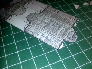
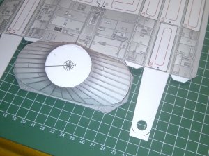
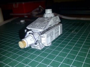
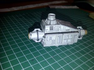
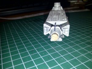
I have finally completed one set, of three, of the spine modules. :thumb:
I decided I would build them in the sets of bottom, starboard and port sides.
Once each set is completed it can be attached to the spine in one go.
This should keep things linear ....
I decided on the level surface of the dinner table as a good flat base, so that everything can be layed out. (and now I can use it without any complaint :twisted

But, after wisely checking the surface with a 1m spirit level, I found that the table surface actually bowed downward slightly across the middle. Not enough that your peas would roll away if you dropped them, but enough to show up glaringly on this particular model. I needed as flat and true surface as possible. I pondered what, until I realized I was holding the answer in my hand; the spirit level itself!!!!
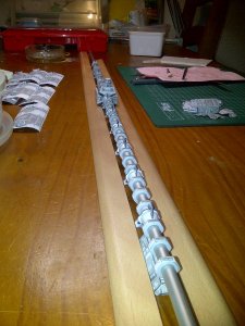
As was seen in a photo from an earlier post, I used two edging strips used in laminate flooring, as a straight edge, (I checked them first with the spirit level). These strips are thin enough to clear the bracket thingies on the couplings between the module assemblies, allowing me to snug the edge nicely to the widest section of the modules themselves.
I used gaffer tape to hold one of these strips to the spirit level, ensuring it was straight to the edge of the level along its length.
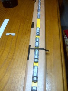
I then placed 4 modules at intervals along the straight edge, and then placed the other straight edge strip on the opposite side of the other, with the four modules in between.
I then taped these down, while applying a GENTLE squeezing action across the strips. Now the gap between the strips match the widest part of the modules perfectly along their lengths.
I then placed all the modules in their respective positions and checked everything FOUR times, using strips of the spine wraps as measuring sticks for the module placement.
The photo should make it a bit clearer...
I sighted along the lengths of the modules to check trueness...
I noticed that the surfaces that mount to the nuts were not that level and a bit wobbily in places.

I used a light and a steel rule to check for trueness.... Plenty of light showing thru

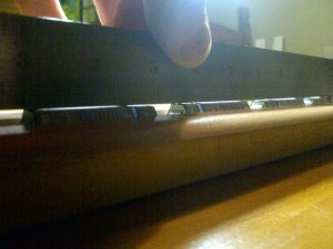
To accomodate for this problem, I decided to use clear silicon as an attachment medium. This should help to eliminate any uneven attachment surfaces. So I turned the spine assembly upside down and added a small blob of silicone to the attachment point of each nut.
I then lifted the whole assembly and carefully, VERY carefully, lowered the spine assembly on to the laid out modules.
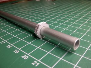
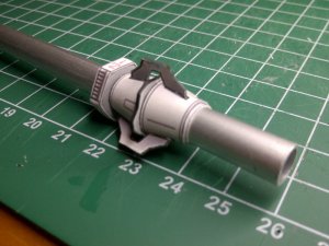
The weight of the aluminium tube and the metal nuts, should be enough to apply enough downward pressure as the silicon dries......
And here it is, in place, with the silicon drying....
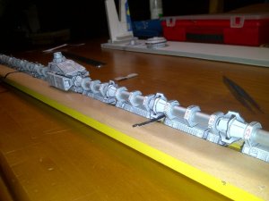
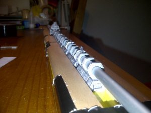
I will take some photos of the results when dried.
But, judging by how long it has taken me to write this, that might be very very soon .:mrgreen:
Next post coming very shortly, I think............


