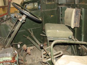
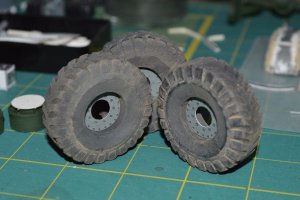
Putting aside my Artillery tractor for a time, going blind and burned out cutting 177 tracks and all the various fiddly bits to go with them! I decided to start another, as I can always switch back and forth, with a fresh eye as to what to do next. First thing I do is research, so I can have a better idea what I am building towards, and also details!
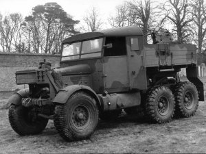
I also knew I wanted to include a detailed ( at least as much as possible ) engine. First off I found out very early on that I was in for it. This is the WAK Scammell Pioneer SV2S fro 2013. Now as this is technically only my 3rd model, some of it may be my own in-experience, but as a draftsman and many other technical fields, I can just say, the instructions and diagrams are just about worthless. For instance, instructions say, put rear-suspension together using picture 8 and general picture 2, picture 8 is only a top view and 2 a perspective view of the complete frame from the bottom..in other word..NOT enough information. I think I have spent more time looking for pars on the sheets, or trying to figure out how something goes together than actual construction!
As it is, I have many parts cut out, some assembly and a lot of things waiting for me to create the proper attachments/parts or all new assembly's as the ones included are not good enough or just completely wrong.
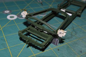
First off is the frame, not to bad, but as yet there are still parts waiting to be glued up till I see if others are going to fit/work or thrown out and scratch built!
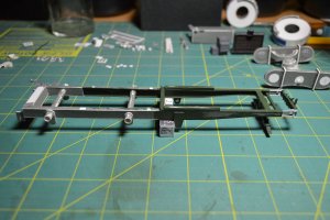
Figured I better get some primer on the inside as it will be very difficult once the rest of the frame goes together.
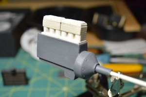
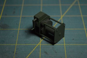
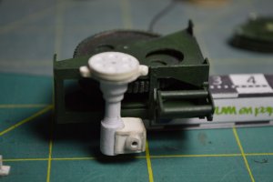
Beginning of scratch built Garner 6LW Diesel. The model has a box with a oil pan and starter and as it says only a basic engine as it can only be seen from the bottom, I say Not in my version! But this also means major modifications to the front end, engine mounts, hood, side panels access panels the lot. It also means cutting and test fitting all the various pieces against each other before glue up or anything else.
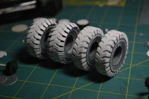
One of the first things I did while building the frame was to start one the wheels and tires and front fenders. As the fenders are formed from flat to a curved rounded form, I used the wheel as a form to get the shape right.
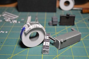
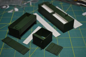
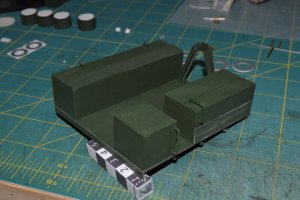
Each cut on the fender was cut, rolled, glued and formed then coated in super-glue to hold shape, sanded and once I prime them smoothed further. Fuel tank has to go in before the cab so got a start as well as changing the mounts and filler cap.
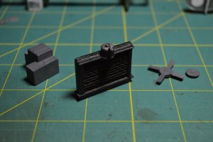
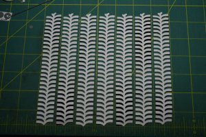
Basic radiator just would not do IE. a box with a printed grid on it, so off to my scrape yard...found some corrugated card used to protect photos when mailed, that was just about 1.5mm thick so cut and stacked thin strips to form the radiator, need to add some tubes and bolt heads, and paint to scratch built case. Basic trans on left few more details to add, and pulleys and fan on right.
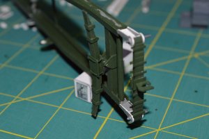
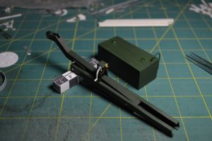
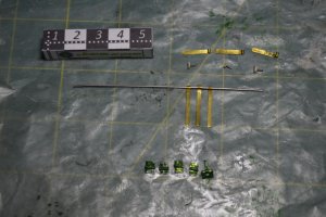
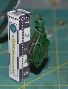
Front frame detail. Front spring assembly. Mount was really bad in kit so rolled a tube out of copy paper around .030 wire, new wrap around bracket to hold it in place, and using same size wire, sharpened and holes drilled using a Pin Vise. Front spring tow hitch assembly, I had to go to reference photos to figure out as kit directions/ diagrams were worthless. One of those things I wish I had caught early as it should have been part of the frame sides! After research decided to go ahead and attach like the real one. Again rolled copy paper tubes around wire. will attach spring to tube then when sanded and installed top pin will be fixed, and bottom will be a removable pin, that allows access to radiator drain etc. as spring assembly swings to Left when pin removed.
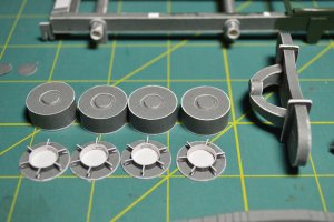
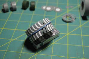
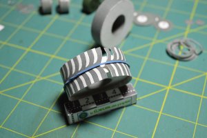
Rear suspension brake drum assembly's, as well as walking beam suspension unit. I will not say much about it as I don't want to get banned! You are referred to the pictures as I said and that is it! and it does not go together very well, as when cut out and the parts were not designed to fit together right. The angle is wrong which attaches the curved left unit to the right beam unit! Again...I say, do not try to roll their rectangle into an axle! I used the paper stick from a Q-Tip then rolled copy paper around that till it was the right diameter! as they say, put a toothpick in the tube as it will be weak and it needs the support to hold up the model! Really? Roll your own..!
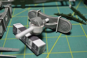
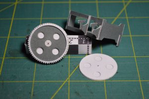
Walking beam with gear box, with "Rolled tube" you can also roll the copy paper around the Q-Tip and if not glued to the Q-Tip you will have a nice axle and "bearing " you can then mount your wheels to the Q-Tip!
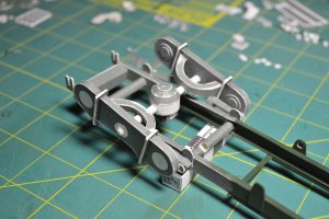
Test fit of rear suspension assembly. Lots of detail to go on this one part alone! still have to work on the springs, bolt heads, hydraulic lines.... lots to go!
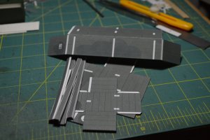
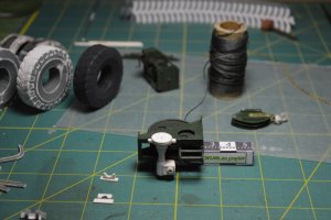
Last one for today..desk top in case I forgot something..trust me this is the clearest it has been in a long time!
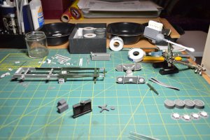
Box in top is full of wheel and tread parts..I'll have some thing to say about those when I post that part!
Next Time....

I also knew I wanted to include a detailed ( at least as much as possible ) engine. First off I found out very early on that I was in for it. This is the WAK Scammell Pioneer SV2S fro 2013. Now as this is technically only my 3rd model, some of it may be my own in-experience, but as a draftsman and many other technical fields, I can just say, the instructions and diagrams are just about worthless. For instance, instructions say, put rear-suspension together using picture 8 and general picture 2, picture 8 is only a top view and 2 a perspective view of the complete frame from the bottom..in other word..NOT enough information. I think I have spent more time looking for pars on the sheets, or trying to figure out how something goes together than actual construction!
As it is, I have many parts cut out, some assembly and a lot of things waiting for me to create the proper attachments/parts or all new assembly's as the ones included are not good enough or just completely wrong.
First off is the frame, not to bad, but as yet there are still parts waiting to be glued up till I see if others are going to fit/work or thrown out and scratch built!

Figured I better get some primer on the inside as it will be very difficult once the rest of the frame goes together.

Beginning of scratch built Garner 6LW Diesel. The model has a box with a oil pan and starter and as it says only a basic engine as it can only be seen from the bottom, I say Not in my version! But this also means major modifications to the front end, engine mounts, hood, side panels access panels the lot. It also means cutting and test fitting all the various pieces against each other before glue up or anything else.
One of the first things I did while building the frame was to start one the wheels and tires and front fenders. As the fenders are formed from flat to a curved rounded form, I used the wheel as a form to get the shape right.

Each cut on the fender was cut, rolled, glued and formed then coated in super-glue to hold shape, sanded and once I prime them smoothed further. Fuel tank has to go in before the cab so got a start as well as changing the mounts and filler cap.

Basic radiator just would not do IE. a box with a printed grid on it, so off to my scrape yard...found some corrugated card used to protect photos when mailed, that was just about 1.5mm thick so cut and stacked thin strips to form the radiator, need to add some tubes and bolt heads, and paint to scratch built case. Basic trans on left few more details to add, and pulleys and fan on right.

Front frame detail. Front spring assembly. Mount was really bad in kit so rolled a tube out of copy paper around .030 wire, new wrap around bracket to hold it in place, and using same size wire, sharpened and holes drilled using a Pin Vise. Front spring tow hitch assembly, I had to go to reference photos to figure out as kit directions/ diagrams were worthless. One of those things I wish I had caught early as it should have been part of the frame sides! After research decided to go ahead and attach like the real one. Again rolled copy paper tubes around wire. will attach spring to tube then when sanded and installed top pin will be fixed, and bottom will be a removable pin, that allows access to radiator drain etc. as spring assembly swings to Left when pin removed.

Rear suspension brake drum assembly's, as well as walking beam suspension unit. I will not say much about it as I don't want to get banned! You are referred to the pictures as I said and that is it! and it does not go together very well, as when cut out and the parts were not designed to fit together right. The angle is wrong which attaches the curved left unit to the right beam unit! Again...I say, do not try to roll their rectangle into an axle! I used the paper stick from a Q-Tip then rolled copy paper around that till it was the right diameter! as they say, put a toothpick in the tube as it will be weak and it needs the support to hold up the model! Really? Roll your own..!

Walking beam with gear box, with "Rolled tube" you can also roll the copy paper around the Q-Tip and if not glued to the Q-Tip you will have a nice axle and "bearing " you can then mount your wheels to the Q-Tip!

Test fit of rear suspension assembly. Lots of detail to go on this one part alone! still have to work on the springs, bolt heads, hydraulic lines.... lots to go!
Last one for today..desk top in case I forgot something..trust me this is the clearest it has been in a long time!

Box in top is full of wheel and tread parts..I'll have some thing to say about those when I post that part!
Next Time....


