1:16 Space Shuttle flight deck
- Thread starter Tonino
- Start date
You are using an out of date browser. It may not display this or other websites correctly.
You should upgrade or use an alternative browser.
You should upgrade or use an alternative browser.
Again about aft joystick mounting...
I eventually was lucky and found, in another very huge collection of original photos (at the Library of Congress website), a nice photo taken at a low angle in the aft cockpit, showing the RHC assembly from a new point of view
View attachment 162982
Since this photo was available for download in a really HiRes format, I was able to focus on a single detail that was the one I was searching for.
View attachment 162983
So I now have a better idea about what is behind the corner
In detail I had confirmation that there is a sort of tube connecting the joystick box to console side wall.
Having this photo as a reference I draw a whole new detail using the same "layers" technic as for the joysticks.
View attachment 162984 View attachment 162985 View attachment 162986
And this is the final assembly
View attachment 162987 View attachment 162988 View attachment 162989
And now the aft section is really complete.
I'm so satisfied with the result that I dare to show it side by side with the real Endeavour !
View attachment 162991 View attachment 162990


!!!!
Is it "LIVE" or is it "MEMOREX"???
Thanks to all of you my friends. I also cannot believe that thing is made by me...
Now we have only one last side to complete, the upper one, the cap for this complex box, and then the inside it's done.
...
Then will be time to think to the outer shell. ;-)
Now we have only one last side to complete, the upper one, the cap for this complex box, and then the inside it's done.
...
Then will be time to think to the outer shell. ;-)
Almost forgot one little thing remaining to complete the seats...
I'm talking about this device hanged on rear of both seats... (BTW anyone can help me understand what is its function? I suppose it's something involved in communications but don't know what exactly).
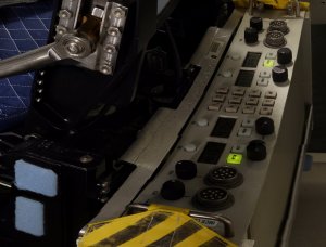
The image is pretty distorted because it's taken from a 360° photo.
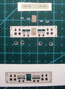
As usual I used a spare copy to add some greebling to the surface. The liquid cristal digits are printed on gloss paper to simulate the displays.
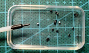
From an (expired) sample collection swab I took this little 1 mm stick, painted it black and cut to realize the knobs.
Even my work equipments helps giving useful materials. The serious modeler look around all the time searching for interesting everyday life objects (isn't true @cylongirl ? )
)
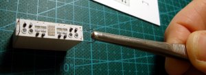
Adding the metal handles...
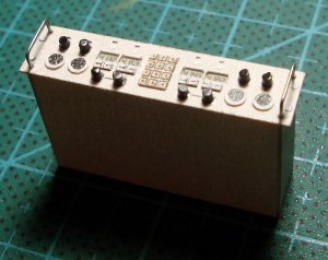
And here is the completed device.
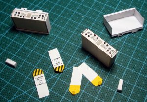
Here are the two devices with the boxes in which they are placed on rear side of the seats.
I'm not sure if the warning plates are placed only on ground or if they are used during operations too. In all the photo I saw they are always present so I'll put them up.
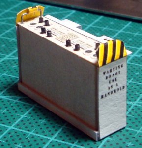
And there is the complete assembly ready to be fixed to seat.
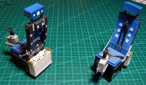

Now seats are REALLY finished and so the lower cabin.
See you soon with "the ceiling part one!"
I'm talking about this device hanged on rear of both seats... (BTW anyone can help me understand what is its function? I suppose it's something involved in communications but don't know what exactly).

The image is pretty distorted because it's taken from a 360° photo.

As usual I used a spare copy to add some greebling to the surface. The liquid cristal digits are printed on gloss paper to simulate the displays.

From an (expired) sample collection swab I took this little 1 mm stick, painted it black and cut to realize the knobs.
Even my work equipments helps giving useful materials. The serious modeler look around all the time searching for interesting everyday life objects (isn't true @cylongirl ?

Adding the metal handles...

And here is the completed device.

Here are the two devices with the boxes in which they are placed on rear side of the seats.
I'm not sure if the warning plates are placed only on ground or if they are used during operations too. In all the photo I saw they are always present so I'll put them up.

And there is the complete assembly ready to be fixed to seat.


Now seats are REALLY finished and so the lower cabin.
See you soon with "the ceiling
Last edited:
Seeing the level of care, detail, effort, and work that you put into this model is simply mind blowing!!!
Just the seat is a model of its own!
Just the seat is a model of its own!
- Apr 5, 2013
- 13,876
- 10,215
- 228
Tonino, this is just so far over that top, I am at a loss for words. I doubt anyone will be able to reproduce this. The seats alone are a complete model in themselves (Geez Rhaven, we think alike!). The research you did for this. Wow, just a big WOW!
Hi friends, time to look up to the... ceiling 
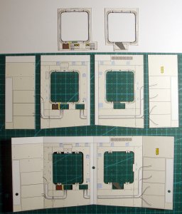
The upper windows are made on 3 layers. The middle one act as a reinforcement for the entire ceiling section to give strenght to the "cap" of the cabin.
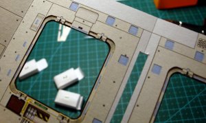
In this close-up the multi-layered window frame is better seen.
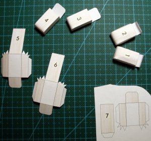
Then I realized the 7 pouches containing the escape cables to be used in case of an emergency bail-out.

After assembling the bags I made some wrinkles to give them a more realistic "fabric feeling".
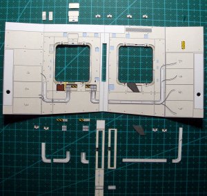
The many details obtained from a supplemental copy of the part to give some "movement" to the ceiling.
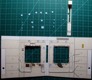
And, as usual, all the velcro patches to complete the work.

The rear section ready to be joined to the front one.
...but before completing the structure I have to think to a way to enlighten the cabin. We need some LIGHTS!
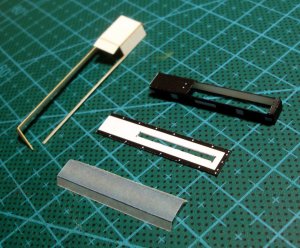
The frosted glass plate was simulated with a piece of tracing paper who is semi-transparent and will diffuse led light (I hope).
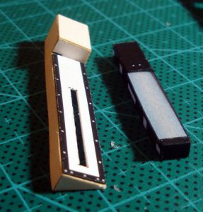
The thin slot in my intention should have simulated the fluorescent tube once the led was placed behind. Unfortunately I had to enlarge the aperture because I realized there isn't enough room to place the led bulb all behind the lamp.
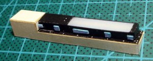
This is the completed part.
...continues...

The upper windows are made on 3 layers. The middle one act as a reinforcement for the entire ceiling section to give strenght to the "cap" of the cabin.

In this close-up the multi-layered window frame is better seen.

Then I realized the 7 pouches containing the escape cables to be used in case of an emergency bail-out.

After assembling the bags I made some wrinkles to give them a more realistic "fabric feeling".

The many details obtained from a supplemental copy of the part to give some "movement" to the ceiling.

And, as usual, all the velcro patches to complete the work.

The rear section ready to be joined to the front one.
...but before completing the structure I have to think to a way to enlighten the cabin. We need some LIGHTS!

The frosted glass plate was simulated with a piece of tracing paper who is semi-transparent and will diffuse led light (I hope).

The thin slot in my intention should have simulated the fluorescent tube once the led was placed behind. Unfortunately I had to enlarge the aperture because I realized there isn't enough room to place the led bulb all behind the lamp.

This is the completed part.
...continues...
Last edited:
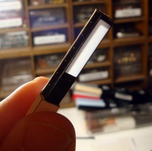
This is the back-lighting test.
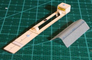
The central light has a cylindrical shape and is realized with another piece of tracing paper.
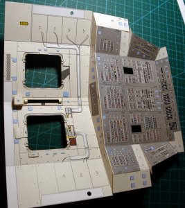
Adding the front section gives the right angle to the completed back section.
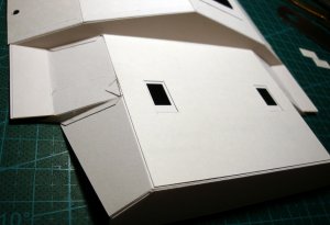
On the upper side I doubled all the surfaces to give some additional strenght to the whole structure.
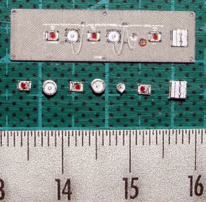
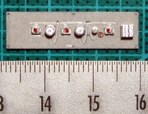
And now, after a long pause, it's time to do some other panel-work. This O18 is a little sampler before going to do the hard work on the front section.
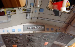
O18 panel in place.
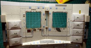
And this is the completed aft ceiling section with all the details in place.
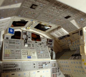
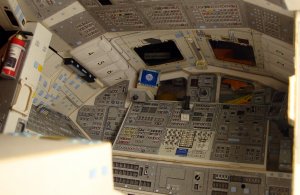
I couldn't resist to place it on the lower cabin to take a shot of the almost completed thing. Very nice!!!
Last edited:


