1/12 Apollo Command Module
- Thread starter Kolokolnikov
- Start date
-
- Tags
- apollo command module
You are using an out of date browser. It may not display this or other websites correctly.
You should upgrade or use an alternative browser.
You should upgrade or use an alternative browser.
- Apr 5, 2013
- 13,876
- 10,214
- 228
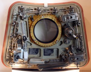
Great job on the panel. I am interested to see how you approach the interior of the door. I posted some good pics of that door. May be worth studying, to improve on the paper model's door. That door is a model unto itself!! I added a Zip file of the huge image. Just for knowlege's sake, the video below shows how the actual latch works. It's simplicity is it's genius. 

Attachments
Last edited:
Great job on the panel. I am interested to see how you approach the interior of the door. I posted some good pics of that door. May be worth studying, to improve on the paper model's door. That door is a model unto itself!! I added a Zip file of the huge image. Just for knowlege's sake, the video below shows how the actual latch works. It's simplicity is it's genius.
I will try to make it as detailed as possible. But I'm afraid I won't be able to implement door mechanization because of too small dimensions. But it's worth a try ...
Excellent!I will try to make it as detailed as possible. But I'm afraid I won't be able to implement door mechanization because of too small dimensions. But it's worth a try ...
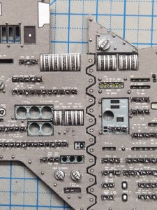
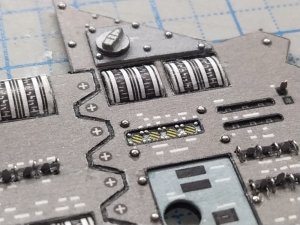
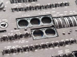
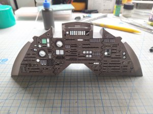
Added a couple more details that are not provided by Ken. One is under the handle, the right of the Alerts display. The second is located in the bottom left of the panel and looks like a joystick. Also, I painted all the rivets in the color of the panel.
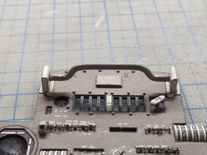
The handle made from the 2mm capillary tube, and painted with gray primer.
When you make a handle, make it 1.5-2 mm longer at both sides, so that it enters its attachments holes, Ken made it size exactly the distance between the attachments.
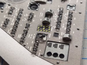
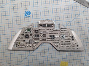

The handle made from the 2mm capillary tube, and painted with gray primer.
When you make a handle, make it 1.5-2 mm longer at both sides, so that it enters its attachments holes, Ken made it size exactly the distance between the attachments.


- Apr 5, 2013
- 13,876
- 10,214
- 228
I think trying to make that a working model would probably make you blind. Seeing the pic does allow you to make a reasonable facsimile though, and seeing your past work, I'm sure whatever you decide, it will look great! 
Assembled and riveted the bottom wall of the panel, which is part of the airlock corridor.
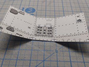
Since I do not assemble according to the instructions, but through one place .. Ken suggests assembling the back of the panel and then glueing all of it. But I decided to go differently, I glue everything to the front of the panel, and the back panel will be glued after installing the LEDs with the wires leading out.
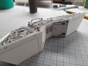
I decided to glue the entire interior space with aluminum tape to reduce the number of LEDs and increase the brightness due to re-exposure, according to the principle of a softbox from a photo studio, and smear the corners with black paint to prevent the paper from glowing.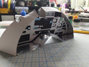
Do not look at the quality of the inner space, it will still not be seen. I just decided not to modernize this part and cut it by eye, this did not spoil the structural integrity.

Since I do not assemble according to the instructions, but through one place .. Ken suggests assembling the back of the panel and then glueing all of it. But I decided to go differently, I glue everything to the front of the panel, and the back panel will be glued after installing the LEDs with the wires leading out.


I decided to glue the entire interior space with aluminum tape to reduce the number of LEDs and increase the brightness due to re-exposure, according to the principle of a softbox from a photo studio, and smear the corners with black paint to prevent the paper from glowing.

Do not look at the quality of the inner space, it will still not be seen. I just decided not to modernize this part and cut it by eye, this did not spoil the structural integrity.
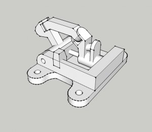
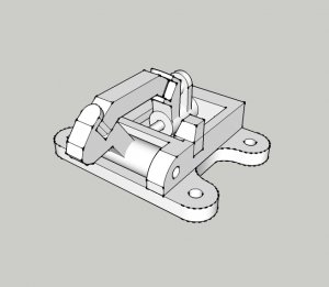
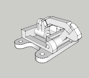
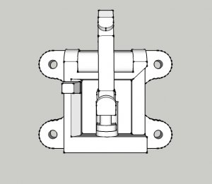
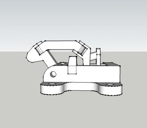
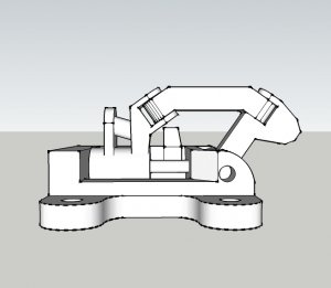
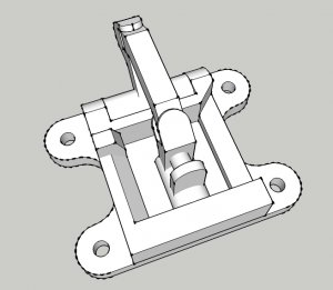
Having seen the video I tinkered a bit around and came up with this:
It is by any means not perfect because I don't have any measurements (and I doubt you could use it on a real Apollo capsule) but if you like I could turn it into a pattern you could use for your super-detailing.

I am delighted, and will definitely turn to you for plans made to fit the dimensions of this part when I get to the assembly of the door.
Secon photo from last post looks fabulous - feels very real, not at all paper and wires. thumbsup thumbsup thumbsup
So SECTION 5 is 99% complete, the rest of the small parts I will finish after assembling all the parts.
Continuing to build SECTION 6. But I have a problem finding pictures of this part of the cockpit, and I need help from the community.
This section is under the crew chairs and the main panel and includes a sextant and telescope, as well as storage compartments.
*Screenshot from instruction.
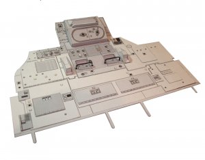
Maybe someone has seen pictures of this part of the cockpit, or maybe someone knows what these elements are (yellow squares)? I would also like to understand where and what rivets and bolts are installed and Ken could have missed them at the time of creating the model.
For now, I will prepare everything for assembly into one big piece. I will partially redo it, for example, there is a toggle switch near the sextant that should be recessed into the panel, but Ken made just a flat detail. Well, I would also like to get as close as possible to the prototype.
Continuing to build SECTION 6. But I have a problem finding pictures of this part of the cockpit, and I need help from the community.
This section is under the crew chairs and the main panel and includes a sextant and telescope, as well as storage compartments.
*Screenshot from instruction.

Maybe someone has seen pictures of this part of the cockpit, or maybe someone knows what these elements are (yellow squares)? I would also like to understand where and what rivets and bolts are installed and Ken could have missed them at the time of creating the model.
For now, I will prepare everything for assembly into one big piece. I will partially redo it, for example, there is a toggle switch near the sextant that should be recessed into the panel, but Ken made just a flat detail. Well, I would also like to get as close as possible to the prototype.


