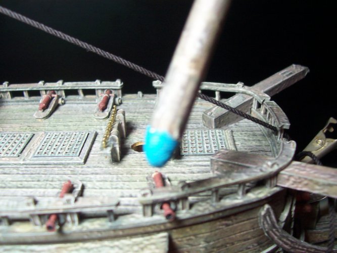
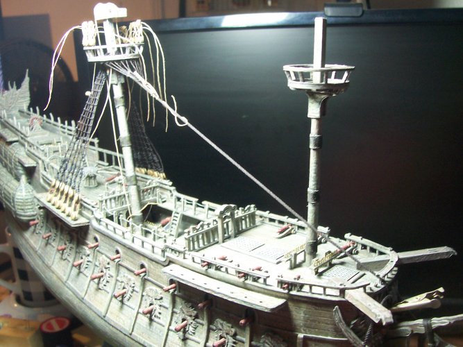
"Flying Dutchman" - Ghost Ship - OREL Russian Paper Model Build

mtrappett

Well-Known Member
Absolutely amazing detail.

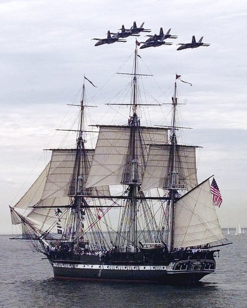
I missed my chance to do the "Chiefs cruise" on the USS Constitution. I was made Chief at sea, and my tour didn't end until after the signing for the "Chiefs cruise" ended. I would have loved to get the training and put to sea on "Old Iron Sides", but missed it.
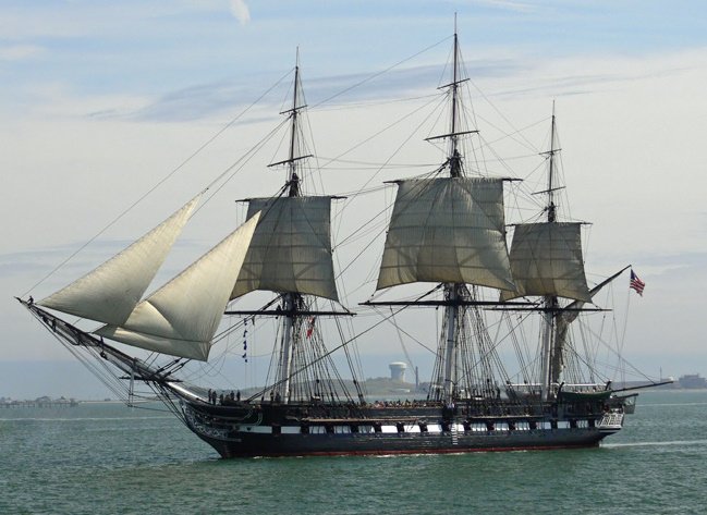
Wow! That's still freakin' awesome Micah! That is such a incredibly beautiful ship! I would love to build a model of her one day!

Old_Ironsides-81.jpguss-constitution-167366cf2fa4cd30.jpg

Thank you also for your comments and reactions! I really appreciate it ;)
 

mtrappett

Well-Known Member
What attention to detail!
You are the kind of builder that I instantly admired and forced me, challenged me, to try Paper models!!
Thank you so much Spaceagent-9 :CHEERS:

That is also a very nice statement you made, thank you sir! The same back at you! You guys have all inspired me to enjoy paper models. I am totally hooked now on paper, and cardboard (to give it a little extra strength in those areas we all know about). I have also found that using some super-thin CA glue on paper gives it much more strength, and on cardboard, turns it into kind of a steel material very strong at least anyways :biggrin::yesyes:
 

mtrappett

Well-Known Member

Lower Main Top​


It's getting too hot for me here in SoCal again. It's 90 in the room here. I was built for the cooler weather I guess.

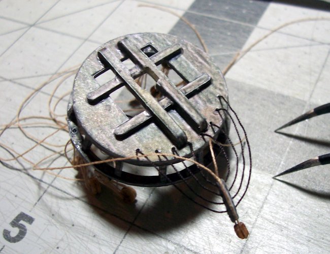
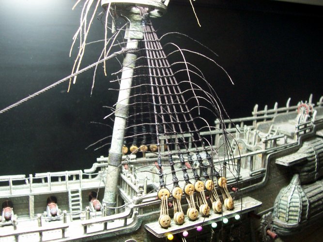
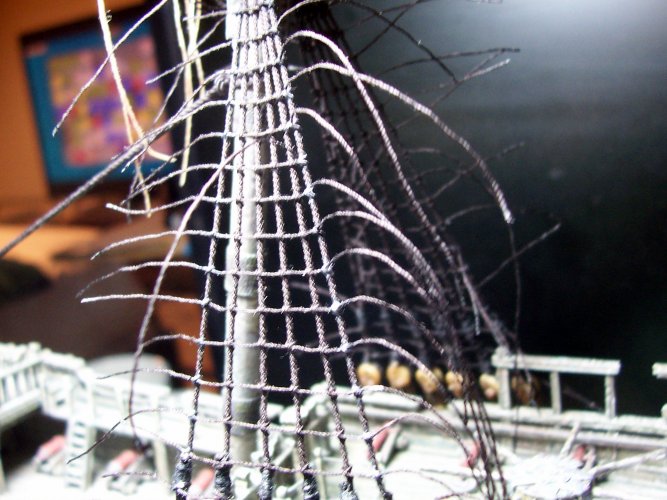
So, I'm continuing working on the lower main top rigging. As mentioned before, it's essential to build each of the assemblies in entirety before adding it to the model. It will be very much easier to do it off the ship :triplets: A little planning will go a very long way here!

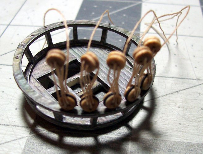
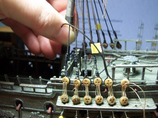
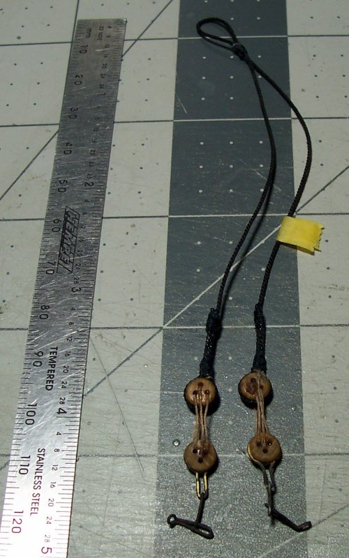
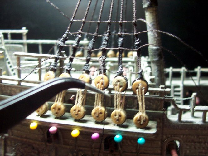
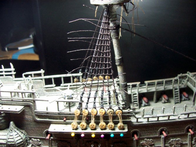
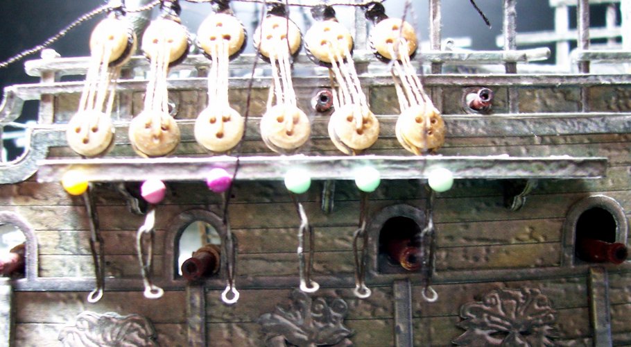
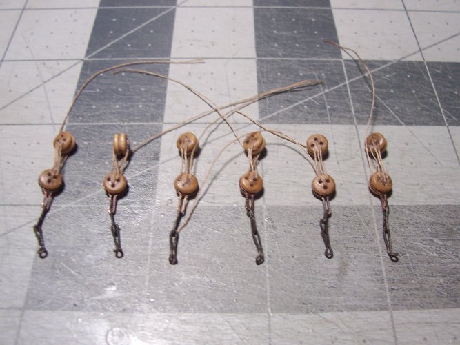
Here are the lanyards that are needed for the upper main mast rigging. There are no futtock shrouds on this ship... :mooner: no, I said futtocks :animated:

001.JPG

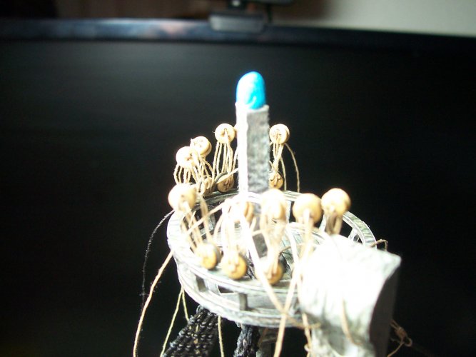
That's all the lanyards in place on the lower main mast, top rim.

002.JPG

The ropes get in the way a bit so just carefully bundle them and move them to one side. These are running rigging so are not coated in tar hence the natural rope.

003.JPG

Lower Main Mast, Euphroe & Crows-Feet Implemention​


That's interesting! The USS Constitution has crows feet and euphroes too on all three masts! I will attach a detailed image further down of the euphroe as it needs to be studied.

The definition of euphroe on Dictionary.com

"a suspended batten or plate of wood or brass pierced with holes through which the cords of a crowfoot are rove to suspend an awning."

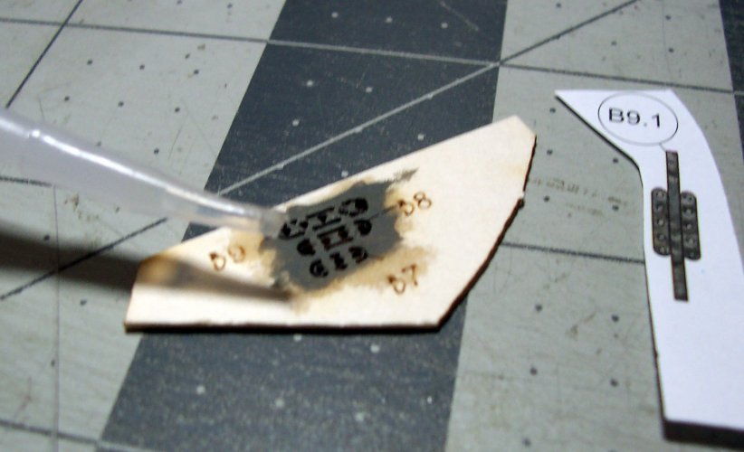
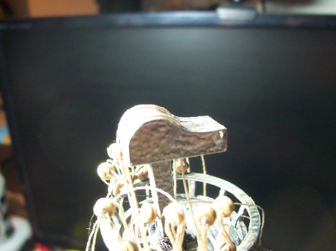
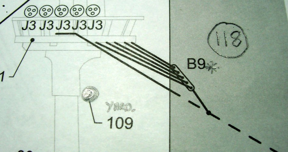
B9.1 is the euphroe that will be for the lower main top. The actual purpose of the euphroe is to prevent the sail from getting fouled up in the top :wink:

This is where you need to flood the part with CA glue to give it strength and stop it from disintegrating on ya Matie! You can see the super-long nozzles I use in the pic below... they are incredible!

004.JPG

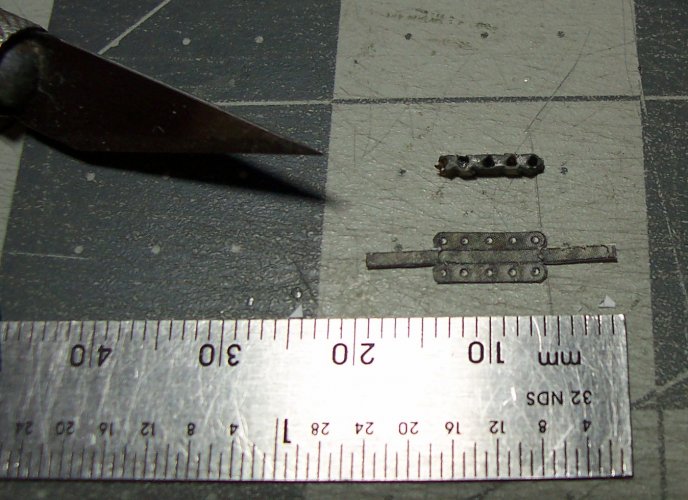
Super-tiny-sized.

005.JPG

Just wrap it up like a little Christmas gift from Santa.

006.JPG

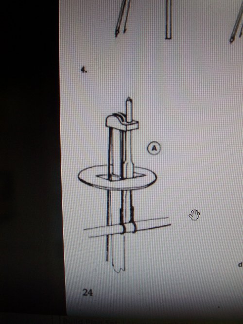
This is what the plan shows for the euphroe's installation... not much :surprise: It doesn't show how to use blocks to tension the crows feet?
007.JPG

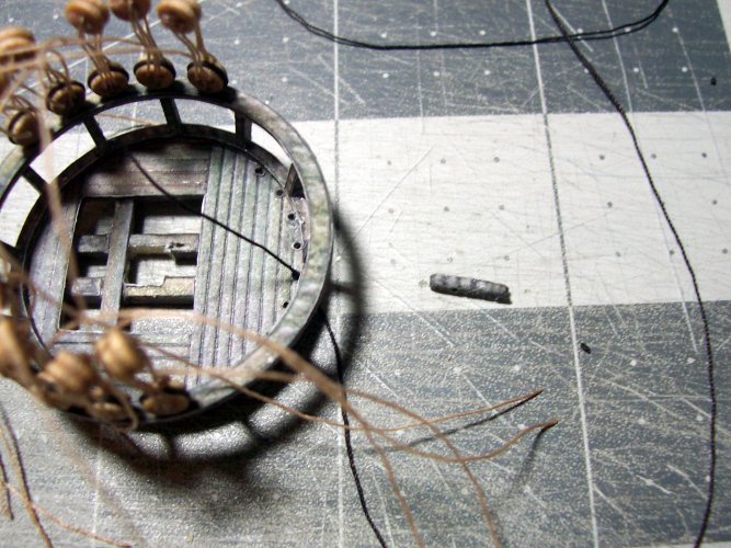
Looks quite inoffensive laying there all on its own!

008.JPG

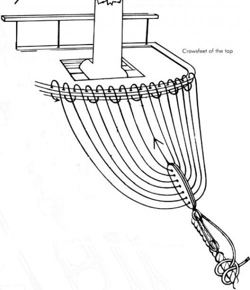
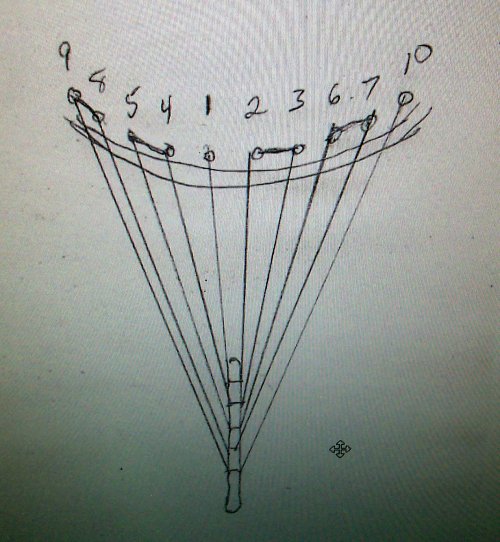
This shows how to thread the crows feet onto the top for the euphroe. I have a diagram for this too that I will attach further down this thread.

This will be standing rigging coated in tar aside from the pulley blocks used for tensioning.

009.JPG


Shrouds for Lower Main Mast​


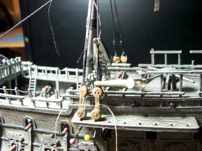
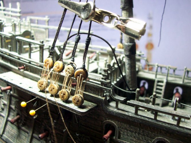
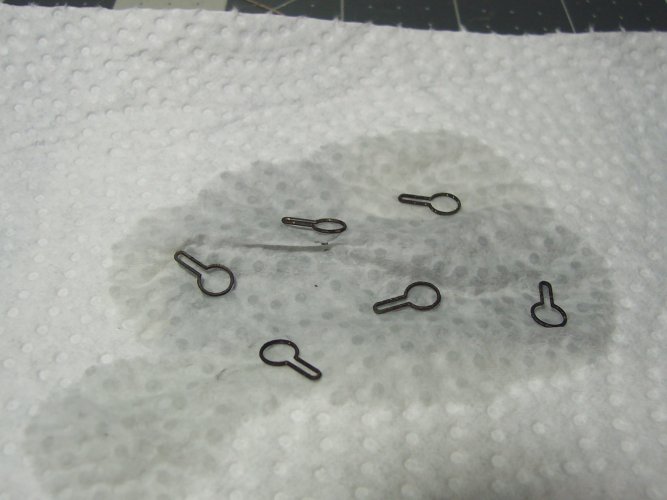
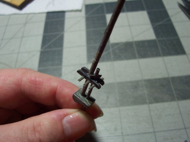
The pins in the picture below help stop the strops from lifting out of the channel holes when the shrouds are tensioned. These are an absolute boon to adding the shrouds! You would see what I mean when you work on this ship model or one like it.

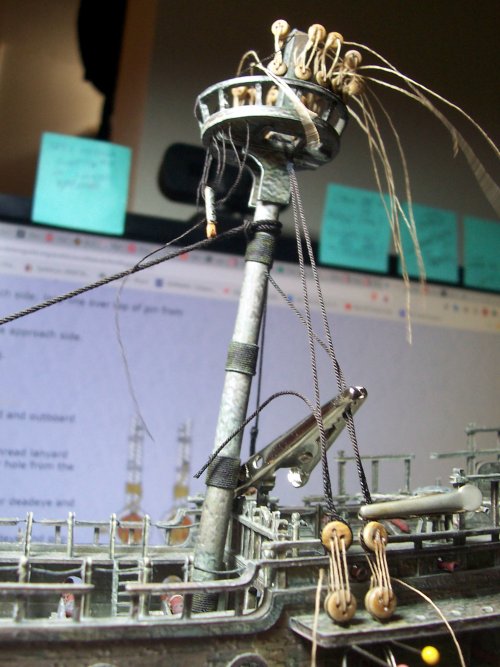
I took the crocodile clip from my electrical multi-meter rather than buying more. Its nice and strong to help clamp the shrouds at the right tension while they are CA glued to the dead eyes.

010.JPG

The shrouds are fitted the same as on a real ship. Each pair are installed starting with the starboard side, the port, then starboard, then port and so on.

Its best not to glue any of these pieces if it can be helped. I never glued the masts, tops, caps, shrouds to the ship and so on, and it provides essential flexibility.

I use a small light-duty croc clip to pinch the line at the dead eye while applying the CA.

011.JPG

Now onto the port side again. You can pull out the lanyard retainer pin to enable the shroud to be removed completely to enable seizing to be performed on the shrouds.

Its so much easier to do them off the ship, and they turn out nicer too! Another advantage of the pins are they prevent the strop / dead eye from turning.

012.JPG

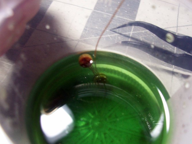
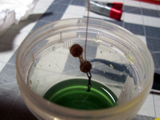
Taking a dip in the black patina acid. Again, it doesn't hurt the other pieces of the lanyard, including the glue.

013.JPG


014.JPG

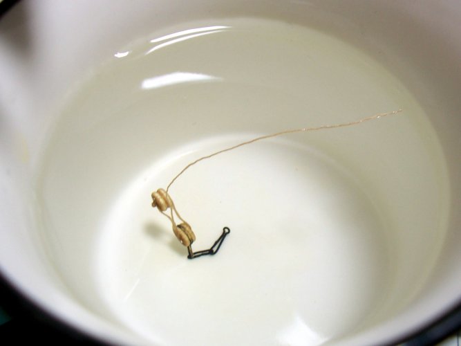
Make sure to fully rinse off the acid in water and let it dry before installation.

015.JPG

I had to open up the holes in the channels with a round needle-file to allow the strop and chain plates to go through.

016.JPG

This is a nice image. I used a little tape to mark the rear shroud of the pair. note that when you take off the shroud, you will need to record its installation because they will be perfectly aligned for that placement.

I experimented with different types of glue for the lanyard rope. It seems to make no difference with looks, but the CA glue makes an instant hold which I found the most useful aspect.

The channel guides are VERY strong and show no signs of not being able to handle the combined tension of the shrouds.

The question of how much tension for the shrouds? Well, that's something that you need to get a feeling for but, I don't overdo it at all. Just a gentle tug while applying the large croc-clip to the lines of rope. Too much and you will pull the mast out of whack :eek::biggrin:

017.JPG

Here is how I apply the seizing to the shrouds. I use about 8" of black regular sewing thread. Some people use fly fishing line as it is super-thin. I tether it on a block of wood, and then roll the thread around the rope end. I finish it by applying a small drop of CA glue, and trim the ends.

018.JPG

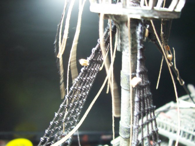
Here are the actual shrouds for the lower main mast. These are 0.76 mm brown rope. These will provide one pair of shrouds for the same side adjacent to one another staring aft of the main mast.

Some things you do not want to CA glue one being the join of the shrouds for the loop. This is best done with white glue thinned 50/50 after seizing. This enables a nice natural bend to the shroud from the mast down.

019.JPG

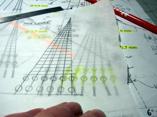
I originally was going to use a commercial jig for building the shrouds and adding the rat lines but after reading some horror stories, I decided it better to add them directly on the ship and also save my pennies. There are no silver-bullets to adding these to the ship! Also, the jigs run about $30 to $150 and you have to know what scale you need?

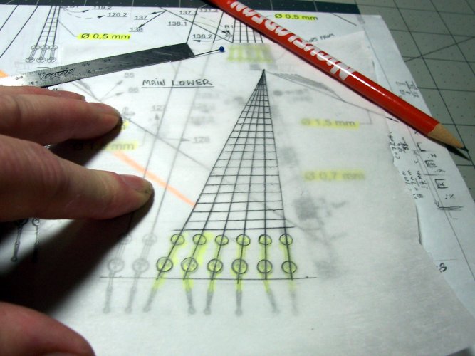
I used some parchment paper to mark out the shrouds and rat lines needed.

020.JPG
 

micahrogers

Moderator "Where am I, and how did I get here?"
Staff member
Moderator
USS Constitution is the Oldest commissioned ship in the US Navy, Launched in 1797, retired from active service in 1881, and redesignated as a museum ship in 1907. She is still used as a training vessel, and as an ambassador of the US Navy.

Amazing work on the deadeyes, and rigging so far. My hands shake too much now to do that type of work. Somewhere in my stash is an old, 1970s vintage, USS Constitution wooden model. Next time I find it, I'll post it, then offer it for sale.
 

mtrappett

Well-Known Member
I spent lots of time researching the euphroes, crows feet, main stays, rattling down, different knots used for rigging, chain plates, strops, and so on, for Dutch built ships of the mid-1600s

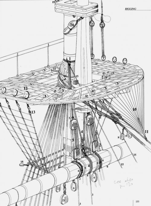
This is one of the most useful pics for explanation of what the euphroe is all about.


5629f1dc716ff10c914e9311f41e8758.jpg

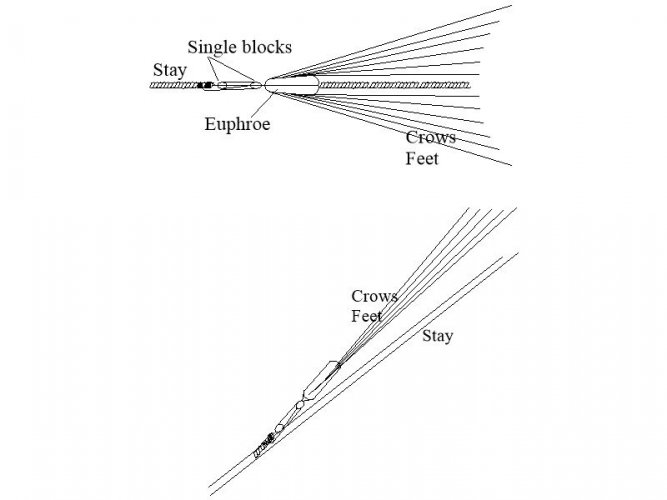
These are how the blocks are used to tension the crows feet. Such a useful diagram :yesyes:

1163684281_CrowsFeetsetup.JPG.db7da72194850b2abbf62c7e8e8d03d1.jpg
11 & 10 are the euphroe and crows-feet respectively.


1894628374_crowsfeeteuphroe.jpg.5e8ff7294cccac476a2ba93f8d4cc600.jpg

Close-up of the euphroe.

post-30-0-44257100-1368645256.jpeg


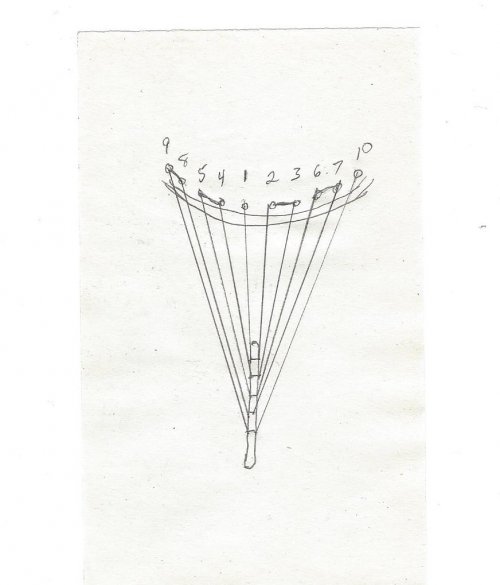
This diagram shows the sequence of adding the crows-feet to the top.

There were 5 holes in the euphroe, and only 8 holes in total in the top so I had to drill another couple of holes at each end for 9 and 10.
post-1079-0-42011200-1455765716.jpg

I found the parchment template to be useless :sadno: The shrouds fall aft of the main mast to some degree and the plan shows them in an impossible place at the square end. This throws off the shape of the shrouds and rat lines :headbange:

021.JPG

Make the seizing and length of the ends of the shrouds consistent otherwise its not going to look realistic, in fact it's going to look like a total poop show :BRAVO:

022.JPG


Adding Lower Main Mast Ratlines​


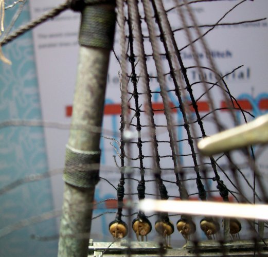
I find working from the bottom upwards on the ratlines produces better results rather than from rattling down, I rattle up as it were :smoker:

By the way, I bust the heads off the pins and just push them into the hull finally, but don't glue them! Its not needed!

You will need to tie many, many, clove hitches for the ratlines to the shrouds. Using two pair of tweezers, one 90 degree, and the other straight, both with pointy ends. Don't glue them until later so you can fiddle around getting them all nice ;) Eventually, just glue the ones on the ends, and leave the ones in the middle. Use white glue for the ends.

  1. The ratlines should be at the same angle as the channel guides.
  2. Push the upper couple of ratlines to the upper-positions to make it easier to complete them.
  3. For the very top one, do the ratline between the pairs instead of the individual shrouds.
  4. Take frequent breaks otherwise this process will drive a person insane :fireguy:
  5. Take the heads of the pins by squeezing them twice at right angles with long nose pliers.
  6. I used 0.2 mm black rope for the ratlines.

024.JPG


This one is pretty much complete aside from trimming all the ends off the ratlines. I painted 50/50 thinned white glue to all the end knots on both sides before trimming them all.

025.JPG

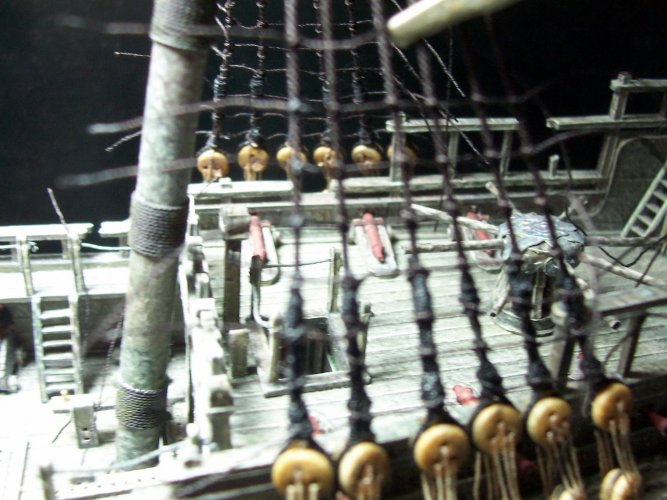
It would help if you were a surgeon used to sewing people up for this process :blueface: One thing is you will be able to make clove hitches in your sleep!
026.JPG

Thread the rope through and around the shrouds.

027.JPG

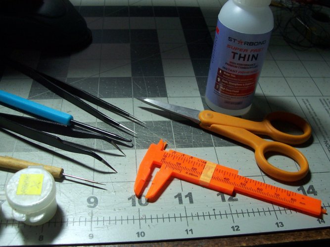
These are some of the tools needed for doing the ratlines.

028.JPG

I completed both sides before final trimming. Its always better to delay the glue process as long as possible I have found with these ship models. I love how these rigging pieces look :bulgeeye:

029.JPG

This pic shows the installation of the chain plates.

030.JPG


031.JPG

I strengthened all of the cannon barrels with CA glue because they are so vulnerable.

032.JPG


033.JPG

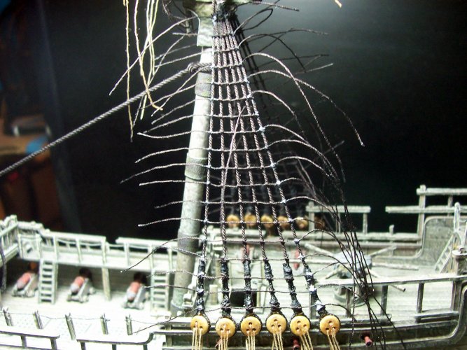
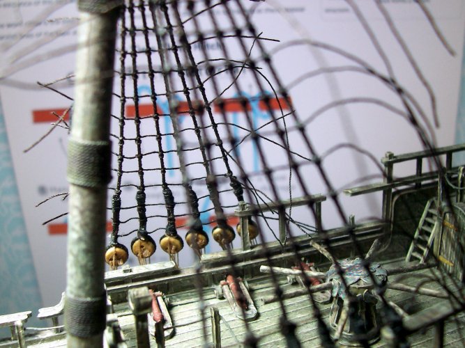
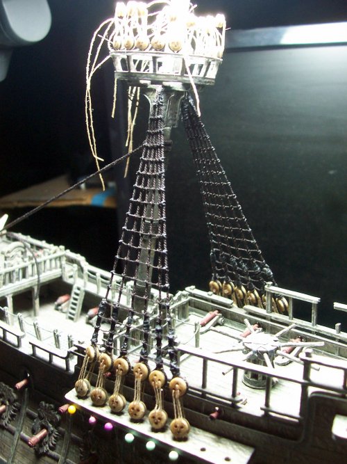
The lower main mast shrouds and ratlines threading are completed.

034.JPG

Finally, removed the heads of the pins and pushed the pin into the hull.

035.JPG

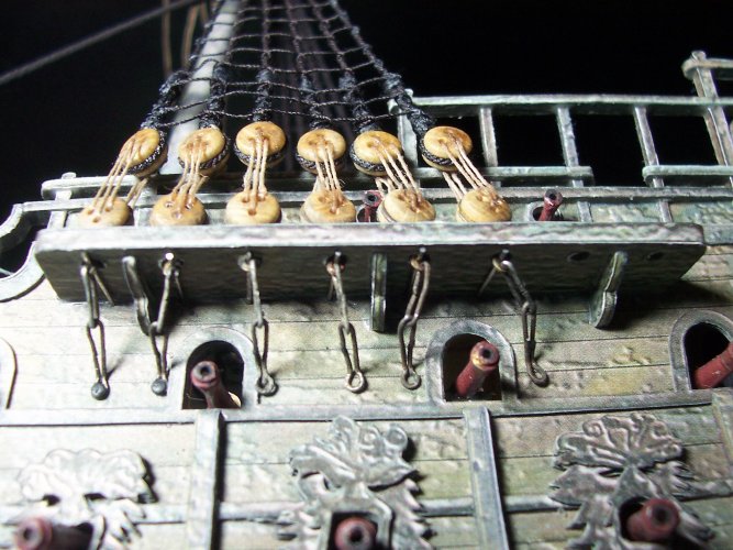
I found some tiny black nails for securing the ends of the chain plates. They are normally used for model trains. Just follow the plans for the correct angles of the chain plates to the shrouds. This will be kind of a compromise because of the location of the gun ports.

I put a dab of CA on to each of the nail heads to stop them coming out.

The first two nails on each side need to be trimmed down because they protrude inside the ship, and they are clearly visible when looking down inside the model.

036.JPG
 

mijob

Tie designer
Staff member
Moderator
Im out of words again. All those ropes are looking amazing this is the next level papervrafting.
 

zathros

*****SENIOR ADMINISTRATOR*****
Staff member
Administrator
Moderator
I thought "euphroe" was a verb, like, "Euphroe it dis way, and Iphroe it dat way". Seriously though, this is a masterpiece.
 

mtrappett

Well-Known Member
The rigging that you are doing for this project is AMAZING!!!
Thank you Rhaven :) I can't imagine how crazy it would have been to climb up those ratlines with the ropes being unsupported from swinging around and stuff? The guys must have to have had nerves of steel? Holy God imagine too when the waves get rough and the ship is shifting so much that you are unable hardly keep on your feet on deck? It sounds awesome! :noteeth:
 

mtrappett

Well-Known Member
Im out of words again. All those ropes are looking amazing this is the next level papervrafting.
You are very kind, thank you! I am sure getting through the rope/twine on this! I'm using much more than I thought it would need, but that's okay. The house manager where we live just gave me a really nice set of hemostats and surgical tools. I got the house some food donations, so I'm in the good books (for now) ;):animated:
 

mtrappett

Well-Known Member
I thought "euphroe" was a verb, like, "Euphroe it dis way, and Iphroe it dat way". Seriously though, this is a masterpiece.
LOL! Yeah, I know! I'd never heard of such a thing before working on this model. These ships are like the Star Wars technology of the 1600s :biggrin: This one I'm building would be like the equivalent to an X-Wing I guess? They share cannons, places for people to pilot the things, lamps / lights, and the ability to destroy lots of stuff, fleets of them, uniforms for the officers, amongst other things. So many different terminologies like euphroes, crows nests, crows feet, buntlines, block and tackles, top gallants, lanyards, dead eyes, sheaves, futtocks, ratlines, shrouds, and a million other things, and they were also as real as you or me. The materials were natural ropes, and wood for the most part of course from living things originally, and that seems to make them almost living and breathing vessels ;):bulgeeye::hammerhead:

I was just thinking about it some more. These paper / card models are also from trees! Plus the masts, blocks, dead eyes, are real wood like walnut, pine,, Beachwood, and so on. The masts of the old ships were made from "old" woods that are not even available any longer.

Thank you too for the ship's compliments Zathros! I have a feeling this will be my last model in this life.
 
Last edited:

mtrappett

Well-Known Member

Ship's Rigging - Continued​


I really do hope this inspires others to try paper models in general because honestly, I LOVE working on them! These tall ship models pose an awesome challenge from what I have found myself, and if you are looking to lose yourself in this stuff, this is what you need to build. I promise you, you will not be disappointed!

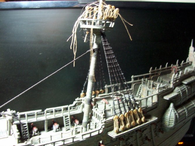
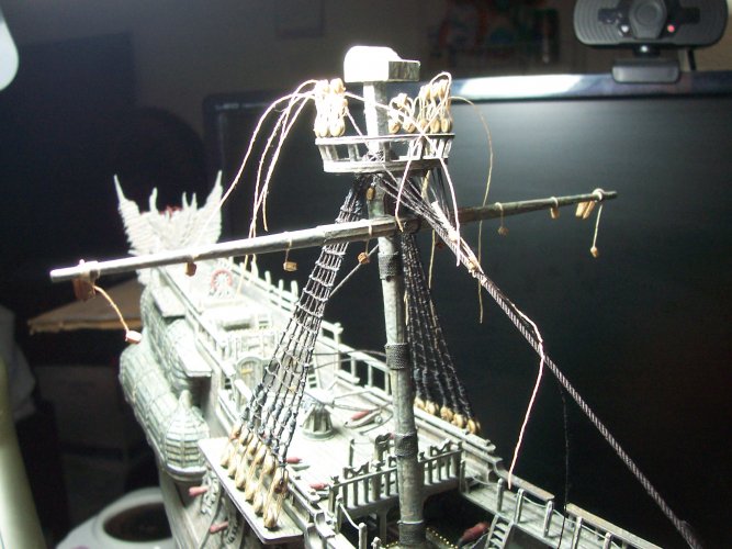
Still finishing up with the mainmast rigging. This is comprised of the crows nest, crows feet, caps, shrouds, ratlines, eyelets, stays, lanyards, and the euphroe.

038.JPG

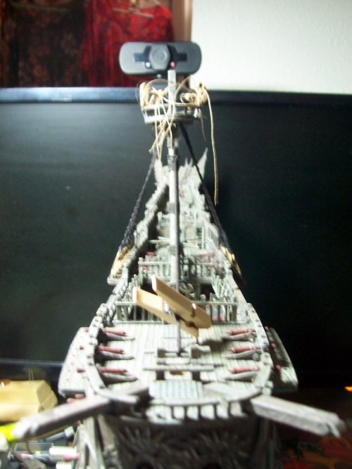
You will need to keep a weather-eye Matie on the angle of the masts as they tend to get pulled around by the shrouds, and stays. Again, try to avoid gluing as much as possible. It will make your life easier trust me! The tiny clothes pins are so useful for keeping things from moving without hurting the materials.

039.JPG

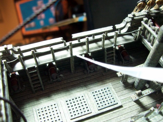
Oh my God, I so recommend this! Use some thin CA glue to reinforce all the joints for the railings that butt against the deck. These are so easily busted off. Use one of the super-thin nozzles to put the glue exactly where its needed, and nowhere else!

040.JPG

This is one of the styles of blocks needed for the ship. It has an eyelet and it seems they actually need to be at both ends even though it doesn't show it here!

041.JPG

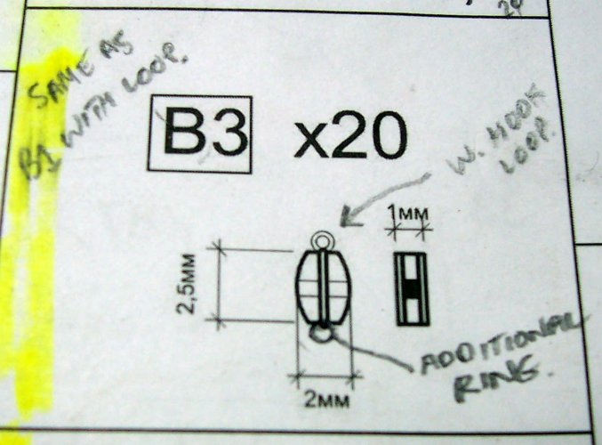
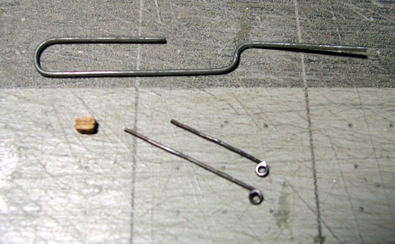
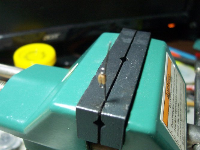
Here's the parts to make the B3 blocks. A paper clip is the perfect size for use to wrap the wire around for the ropes to pass through.

042.JPG

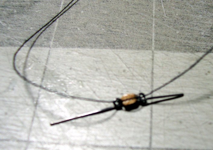
I used CA glue to hold the pieces together before using the rope to provide some strength.

043.JPG

Just trim off the excess wire off the eyes as the final stages.

044.JPG

Just an experiment for a block I was working on.

045.JPG

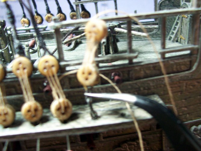
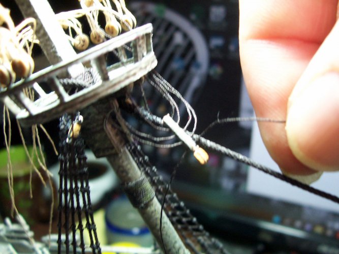
This is the mainmast euphroe, and crows feet. I added a block to the end of the euphroe per the real ship. There must be an adjustment for the tensions of the loops.

047.JPG

This diagram shows how to string the crows feet through the euphroe and crows nest (top).

048.JPG

This end will pass over the square mast head. It is a loop that will slide along the stay. Note the mouse that stops it from going too far. I just used a bunch of turns of thread to provide the shape of the mouse.

001.JPG

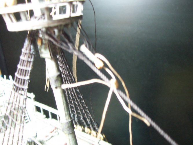
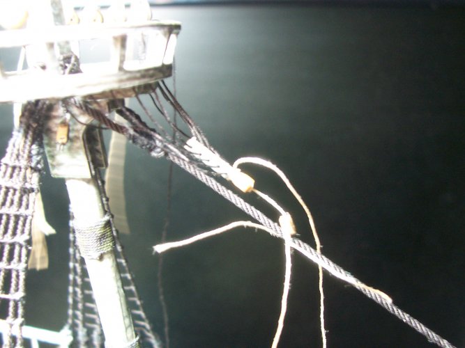
The euphroe finally getting strung into place on the mainmast. Note the blocks, one on the stay too that will assist with tension adjustment.

002.JPG

Note that these are pulleys used for adjustment so they will be natural color based on the fact they are not tarred.

003.JPG


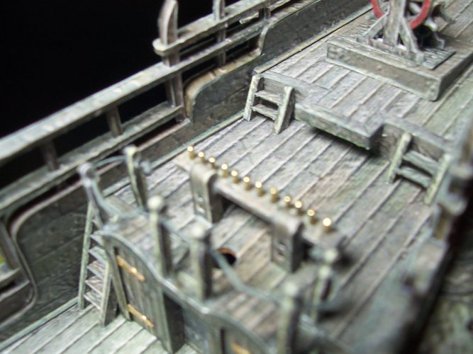
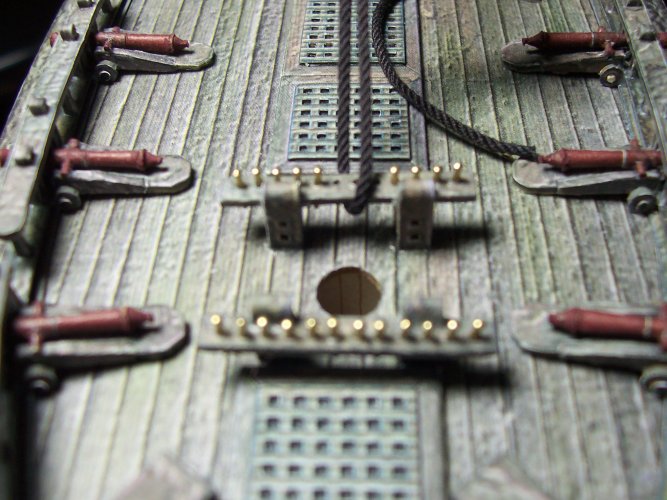
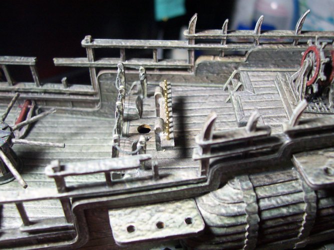
Installation of the Belaying Pins (X 64)​


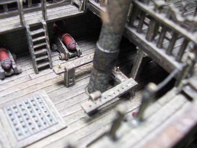
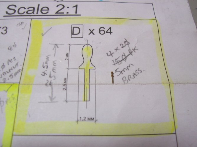
The belaying pins are used to hold the ropes at the correct position. I decided to use brass ones. These are the closest to the size they put in their diagram.

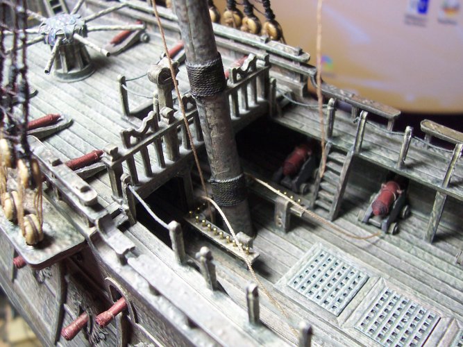
The 'U' shaped deal at the bottom of the mast is called the, "fife rail".

004.JPG

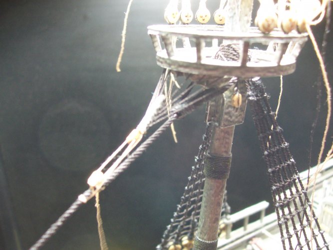
Quite a complex assembly - the mainmast top.

005.JPG

Diagram for needed belaying pins. The scale of the plan is off a bit as can be seen here :hammerhead:

006.JPG

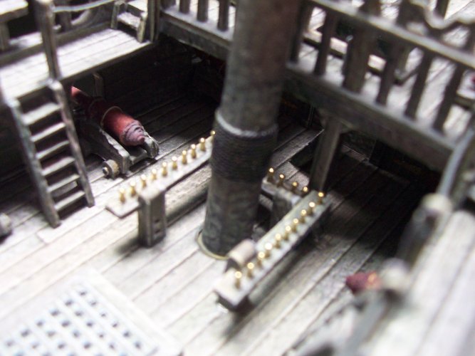
They look nice I think?

007.JPG

This is the pin rail at the mizzen mast.

008.JPG

These are the pin rails for the foremast. Note the temp stay for the mainmast lashed to the aft pin rail.

009.JPG

Just a dab of CA glue to hold the pins in place in the rails.

010.JPG
 
Last edited:

micahrogers

Moderator "Where am I, and how did I get here?"
Staff member
Moderator
We had to sail "Uncomfortably Close" to a Level 4 Typhoon in the mid pacific. I was on CG47 at that time, 25 foot waves were quite sickening, and no one was allowed to go on deck..

Keep up the amazing work on this beauty.
 

mtrappett

Well-Known Member
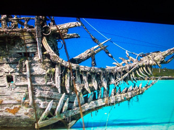
Here's a pic I found of the real ship they built for the POT movies. It looks pretty narly to me!!

011.JPG

Bowsprit Gammoning​

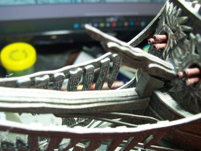
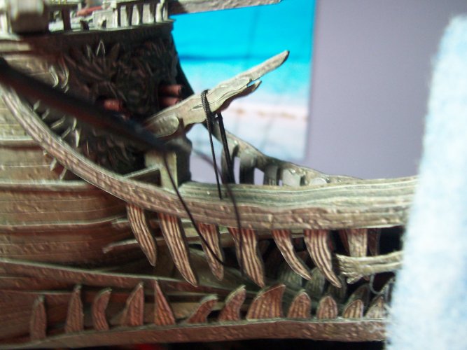
One of the first areas to rig on a model ship is the bowsprit and beak. This is a closeup pic of them.

012.JPG

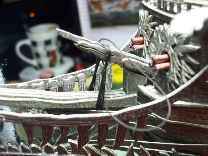
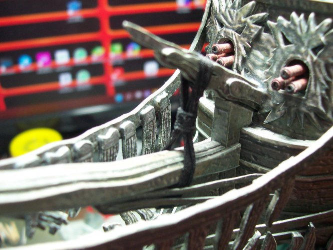
The rigging that goes around the bowsprit and the beak is called "gammoning". This was never included in the model. I did my own research, and added this to the ship's mix.

This allowed me to try out my new belaying tools to get used to them a bit. Its accurate so far as I can interpret.

013.JPG

There's a special way of roving the rope which I found in my book I bought called The Rigging of Ships".

014.JPG

I like the look!

015.JPG


The Lower Mainyard​


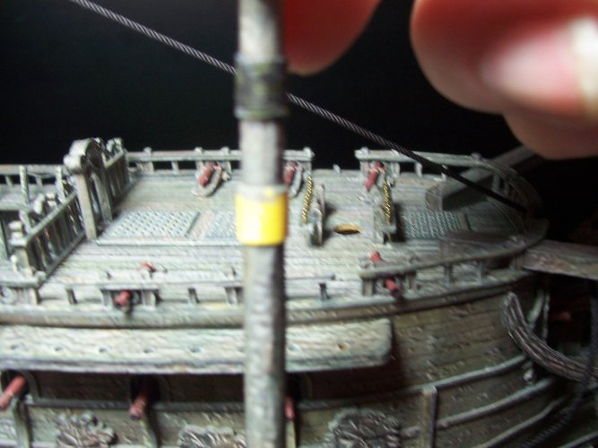
Next on the list is adding the rigging to raise and lower the lower mainyard. There are 2 ropes that loop over the top and down to the fife rail below on the deck at the base of the mast.

016.JPG

I found it worked well to drill a hole through the yard and into the mast and then put a tiny nail to hold the yard in place while working on the rigging. Eventually, this will be replaced or supplemented with the real fixing which is called the parrel.

Note that the yard is fully rigged as a unit prior to adding to the ship.

017.JPG

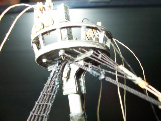
Pretty nice view of the underside of the top / crows nest.

018.JPG

As mentioned throughout the build, it is better to avoid gluing permanently in place the masts, caps, tops, shrouds, and so on. I used just a little blob of blue putty to hold the caps in place on the top of the masts. I also use it on the base of the masts during stepping them.

019.JPG

Here's the running rigging for adjusting the height of the yard on the lower mainmast. This will work as on the real ship. The lines were purposely left long until finalized.

020.JPG

I completely coated the caps in thin CA glue. This really stiffens the paper. Drill a couple of tiny holes for the rigging that loops over the caps. Also note the 2 eyelets (H) placed opposite each other on the beak of the cap.

021.JPG

Its starting to get a bit busy with all the ropes. Look at all of those clove hitches! There are hundreds of them!

022.JPG

I found the mainstay was difficult to work out where it was actually fixed on the deck end. I started by thinking it went down the front, and through the rail to the beak. Then, after carefully studying all my sources, I finally feel comfortable with its new location.

Stepping the Lower Foremast​


I wrapped a little Tamiya masking tape around the base of the masts where they locate with the deck. This helps to remove any sloppiness in the stepping process.

023.JPG

Placement of the lower foremast with a bit of blue putty to keep it from rotating around when the rigging is pulled.

024.JPG

Looking at the mainstay that will eventually be re-done based on new research. The plans are VERY vague in all the rigging areas.

025.JPG

Strops for the dead eyes that will be fitted to the channels on either side of the lower foremast. They are just drying after being dipped in acid.

026.JPG

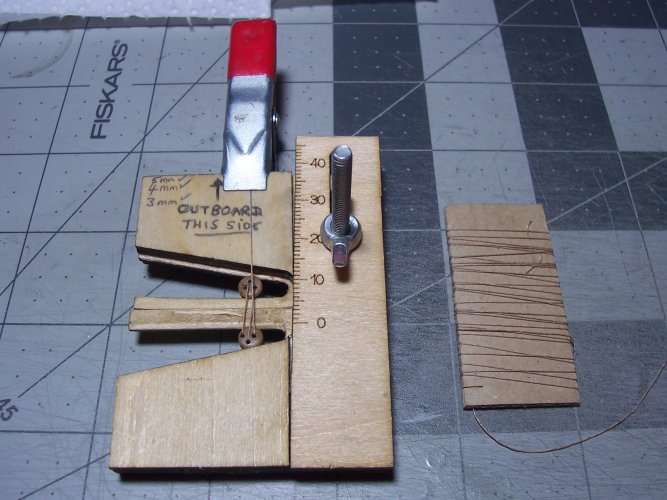
Building the 5 mm lanyards for the lower foremast and shrouds.

027.JPG

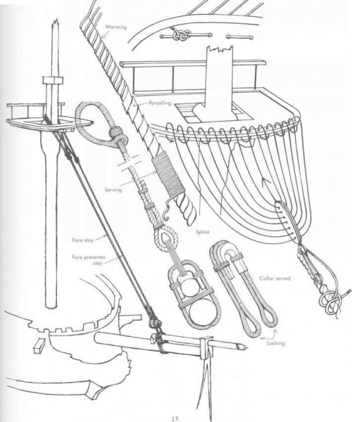
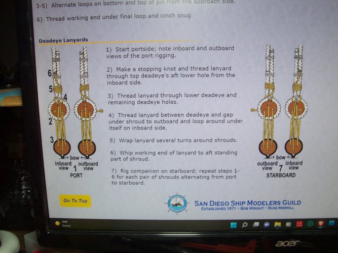
Here's a diagram I found online for making the lanyards. Note that they are different for port and starboard sides. I marked up my jig accordingly to make it easier to get it sorted out.

028.JPG

Not ready at all for these yet, but I did take some time to spread CA glue on all the cross trestles and cross trees to strengthen them all up a bit.

029.JPG

Lanyards ready to be installed for the lower foremast. 6 will make one side. Its best to solder all of the joints for the links and chain plates to stop them opening up when they are under strain.

030.JPG
 

Chuffy70

Well-Known Member
Fabulous work on what looks a very interesting kit, love the mixed use of materials to build this up...fine work Sire
Do they do anything else and is there a website?
 
Top