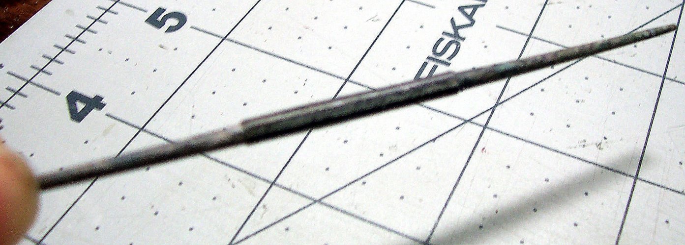
"Flying Dutchman" - Ghost Ship - OREL Russian Paper Model Build

Rhaven Blaack

!!!THE MAN BEHIND THE CURTAIN!!!
Staff member
Administrator
Moderator
Jun 12, 2009
12,538
9,926
228
Oregon
www.deviantart.com
I hope so. I really love this ship, and there has to be others out there too that could feel the same way.

One thing I really like is that the "kit" comes with all of the necessary accessories such as all the cannons of which there are three types, stand, anchor, figureheads, deadeyes, blocks, winches, and so on. If these were to be bought as add-ons, it would become VERY expensive!
Oh, I could not believe that there would not be others like this available (where there is one, there are more).

This is a kit looks like it is not for beginners (or even intermediates for that matter). However, it does look like it is well worth the investment.
 

mtrappett

Well-Known Member
Mar 3, 2013
373
812
75
Santa Clarita, California
I hope anyone that is reading this is doing well, and you are enjoying what you are currently working on. Thank you for stopping by to take a look... I appreciate it very much.

This is as I'm sure you are aware, the Disney version of the Flying Dutchman ship from the Pirates of the Caribbean movie chain. although there is no mention of this in any of the documentation. The regular version of the ship is much more basic, and has none of the cool detail that the Disney version has.

There is hardly any naming given for the ship's parts such as dead-eyes, foremast, mainmast, mizzen, crosstrees, tops, caps, and so on. It looks like it was approached with the view of abstracting away any ideas that you are building a ship, and just following a numbered sequence instead. That seems kind of sad in many ways, as there is so much detail in the build. I decided to delve deeper and read some books on the subject of how these old ships were designed and built. It has also helped a great deal in understanding about the model. This is a Dutch built ship of around the 1600s basically. It may not be real, but they did build a full-size version for the movies. I totally recommend looking at some of the old books out there, and I will list them eventually at the end of the build, if that day ever comes :drinksmile:

You might be thinking that the stand signals the end of the build of the ship? Well, that is so much further from the truth! There is still about half of the model to accomplish building, believe it or not? :surprise:

The Ship's Stand​


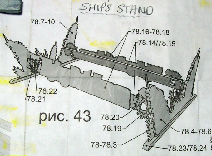
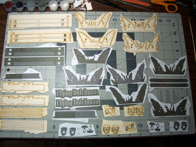
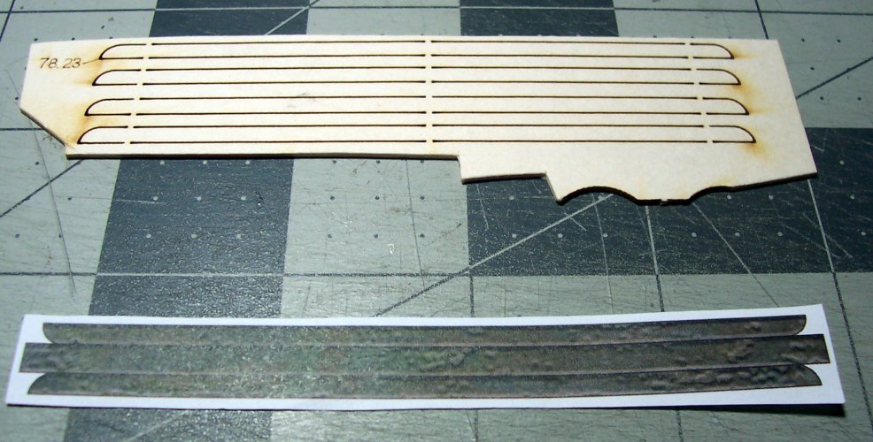
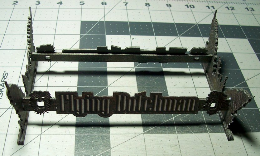
Pic 43 below shows how the parts need to be put together. They are the parts 78.xx sequence.

043.JPG

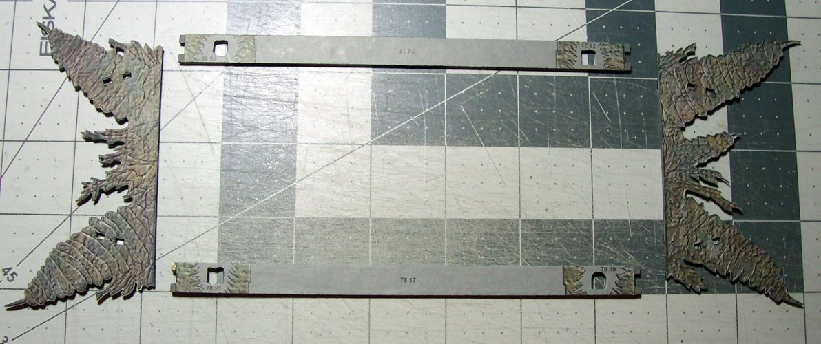
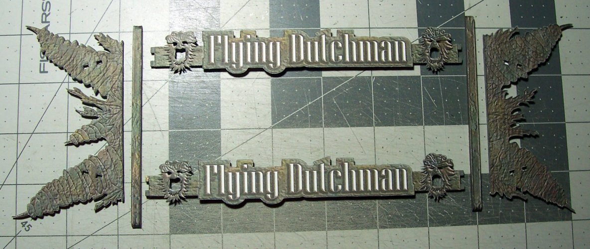
Here are all of the ship's stand parts laid out for ease of building. I usually put the pieces in a Ziploc bag and pull out the ones I need.

044.JPG

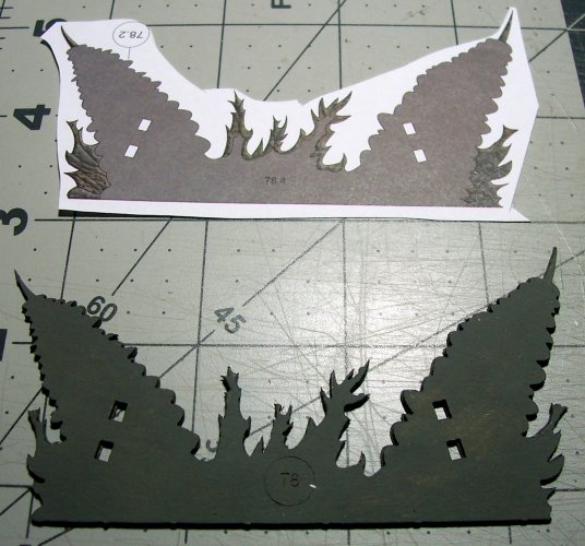
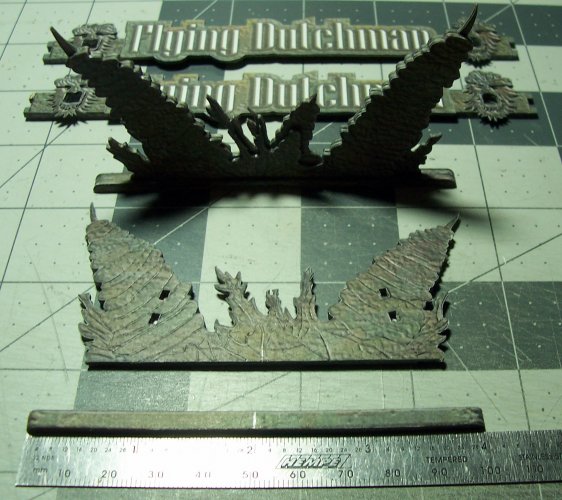
Build the ends of the stand.

045.JPG

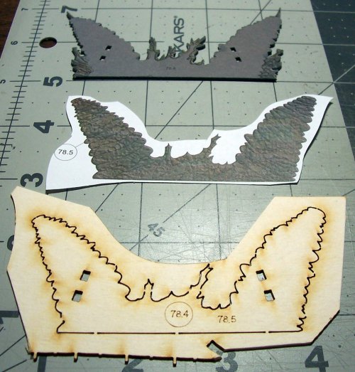
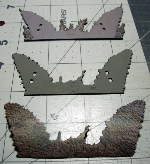
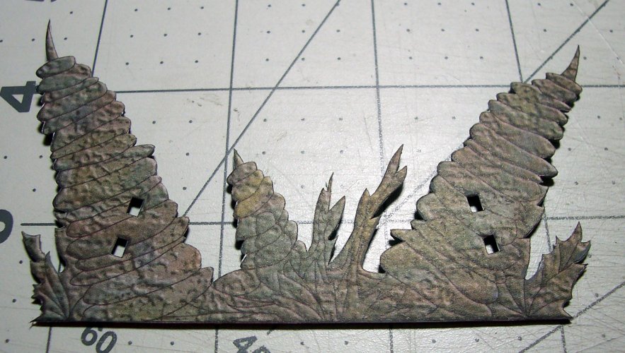
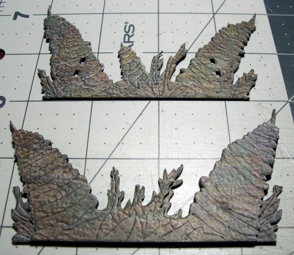
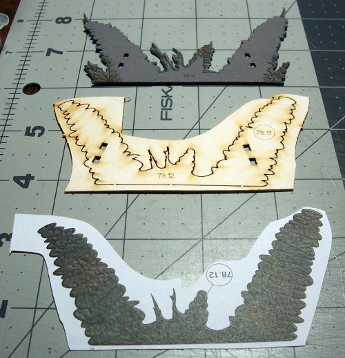
It is layered for a 3D effect and to provide enough strength to support the model. The usual card and color veneer pieces below.

046.JPG

The next layer being constructed. All of the surfaces where parts will be fitted are numbered.

047.JPG

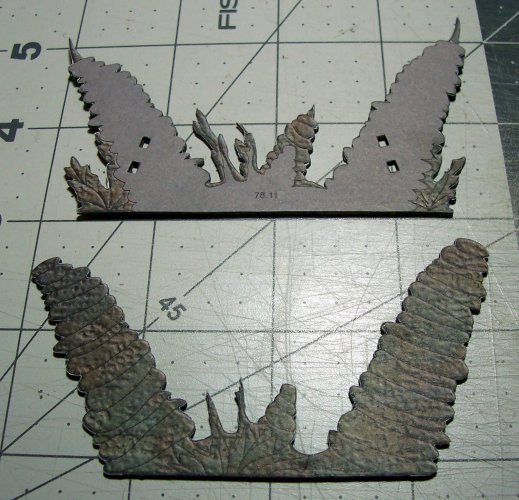
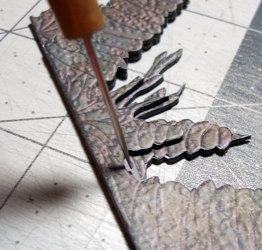
I took extra time to score the lines to give a better effect (last image in the sequence below).

048.JPG

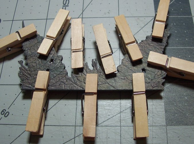
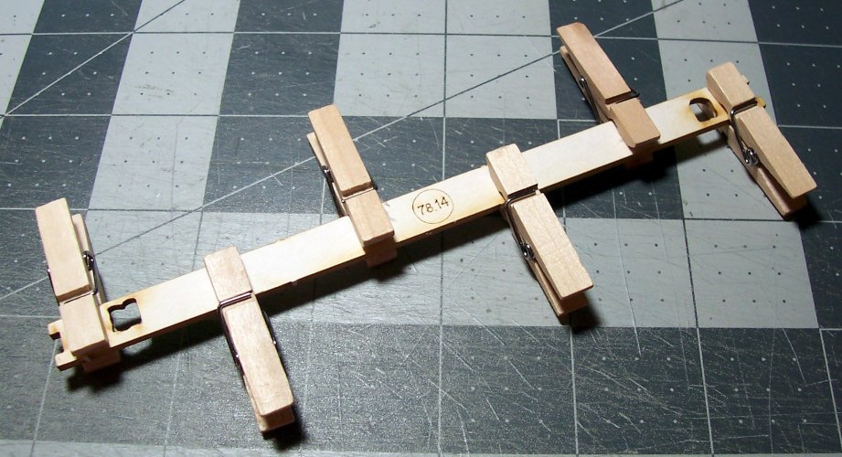
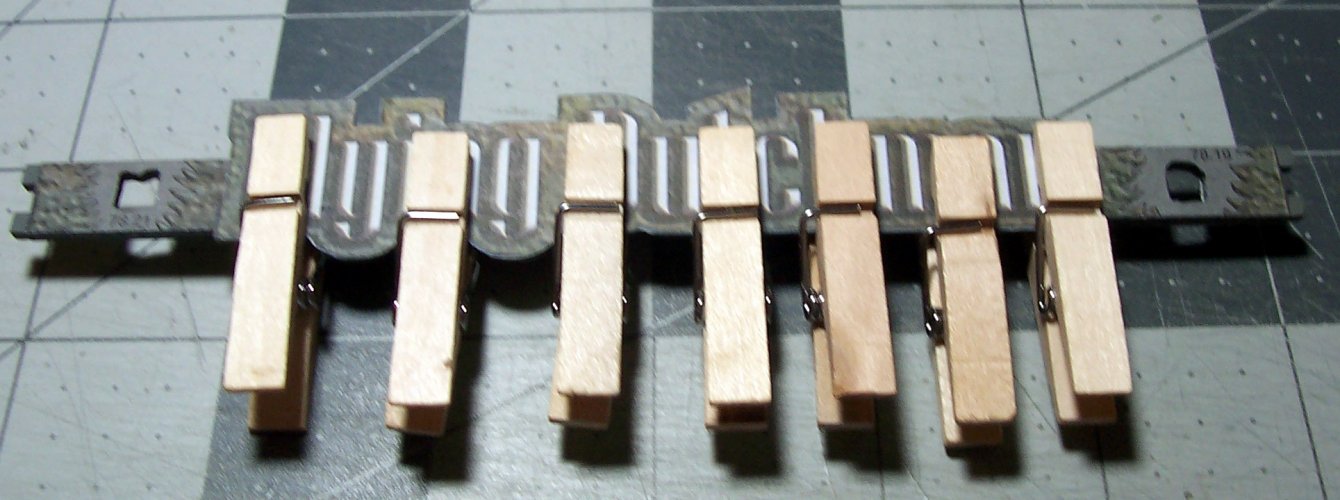
I get a bit paranoid with clamping as can be seen here :bulgeeye:

049.JPG


001.JPG


002.JPG


003.JPG


005.JPG

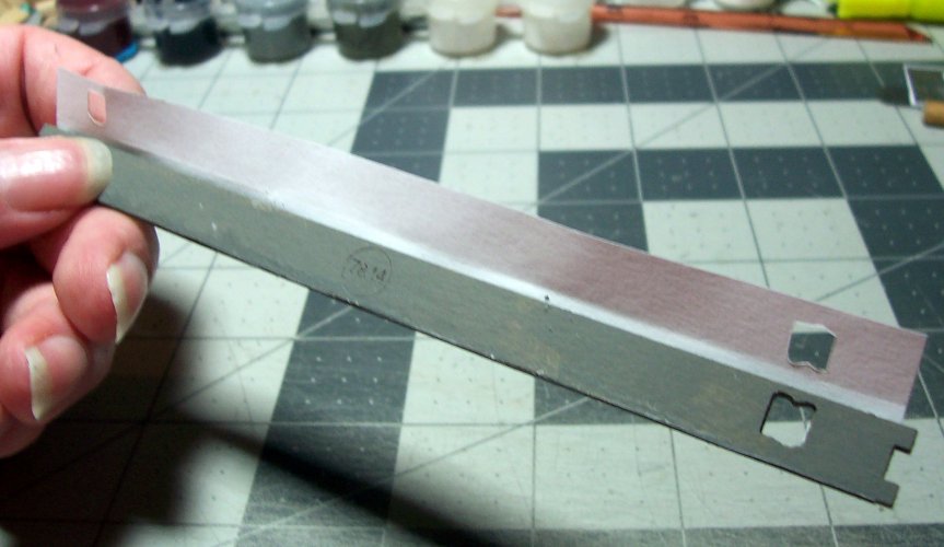
There is a weak spot which I identified below. I just built a glue-gusset to provide additional support.

006.JPG

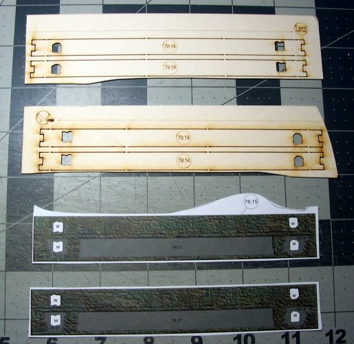
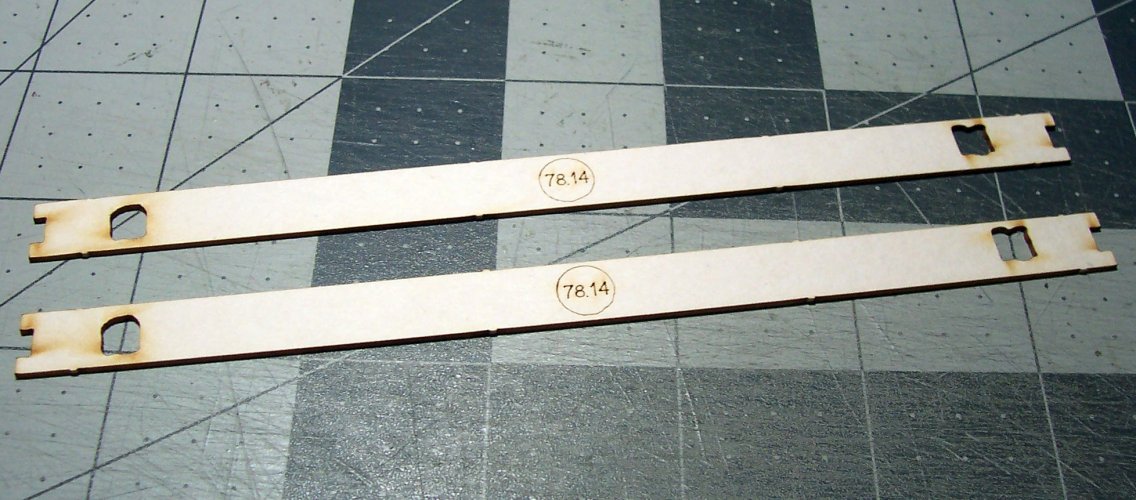
Now to build the sides. There are 2 layers, so be aware because the plans never mention multiple layers.

007.JPG


008.JPG

Make sure the body of these stay flat and true. As the glue dries, it tends to warp them a bit. Just put them under a heavy book overnight.

009.JPG

The color veneer just wraps around the sides.

010.JPG

Just glue a portion at a time.

011.JPG

There is actually quite a lot of work in the stand. It is definitely a sub-project.

All the sides completed.

012.JPG

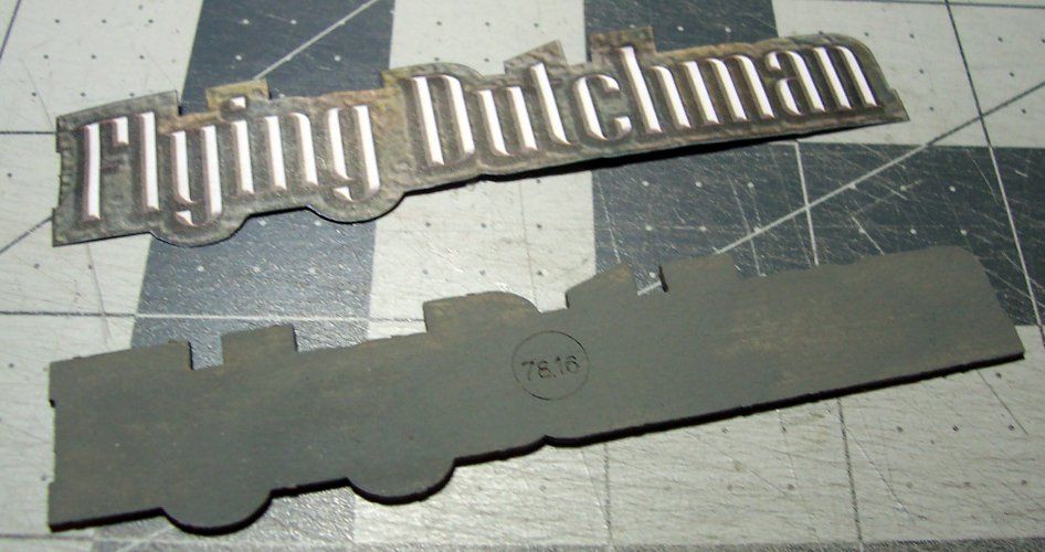
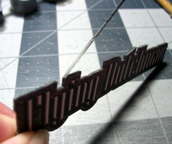
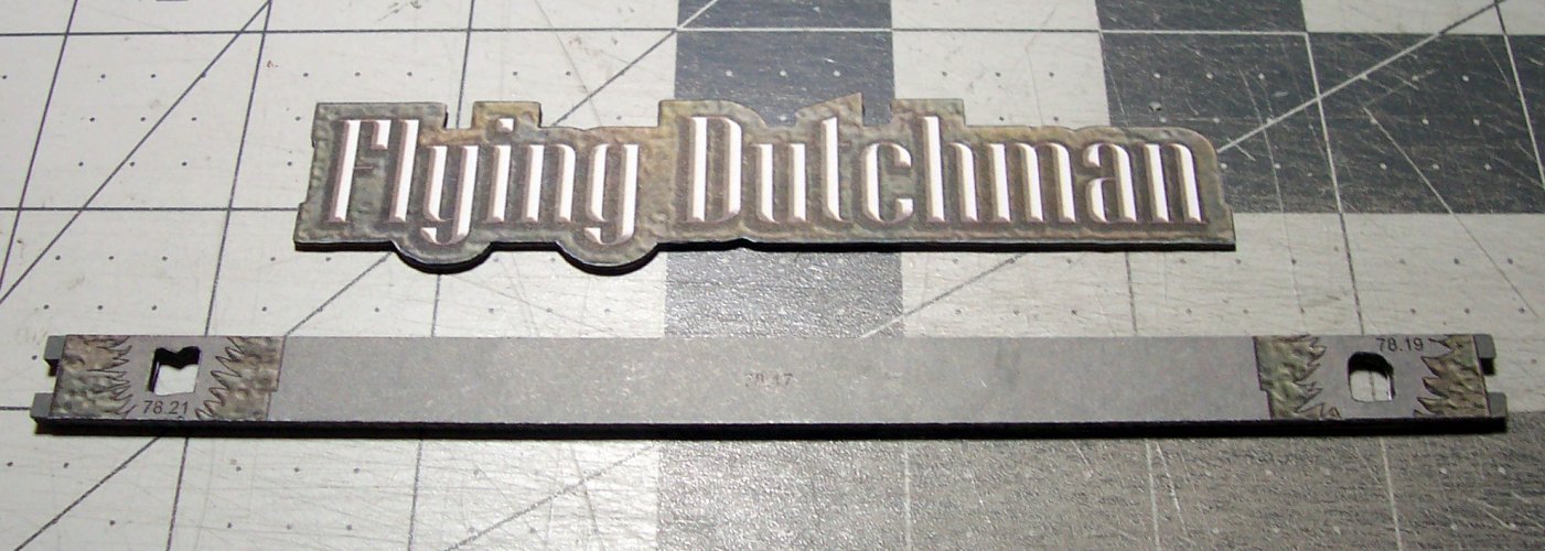
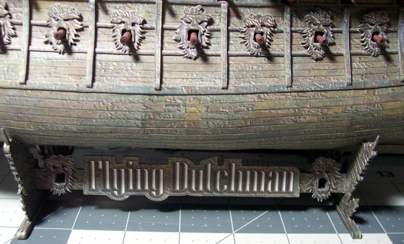
Next, the nameplates for each side of the stand (port and starboard).

013.JPG

Some delicate cutting of the name color veneer is required. This is a focal-point so spend some extra time with the nice sharp edges.

014.JPG


Next. completing the stand.
 

Rhaven Blaack

!!!THE MAN BEHIND THE CURTAIN!!!
Staff member
Administrator
Moderator
Jun 12, 2009
12,538
9,926
228
Oregon
www.deviantart.com
Yes, I have been enjoying this thread and seeing the work that you have been putting into this project! Thank you very much for sharing this with all of us! Like I had mentioned earlier, this thread is a perfect guide for anyone who is interested in trying their hand at this model!
 
  • Like
Reactions: mtrappett

mtrappett

Well-Known Member
Mar 3, 2013
373
812
75
Santa Clarita, California
My wife reminded me the other day that I work on my ship every day, for most of the day! :eek: When I wake up, I just have to start the day by working on the model. I work into the wee-hours of the morn' as well. I must be crazy, that's what she tells me anyway.

Any old way, lets continue with the stand. Its all about the detail, so here we are adding the "ribbon" that goes all around the edges of the nameplates. Kind of a challenge, but makes the things look better in the long run I feel?

015.JPG

There are 2 required of each of these plates per side of the stand.

016.JPG

Make sure there are no bubbles or places that show that you missed the glue!

017.JPG

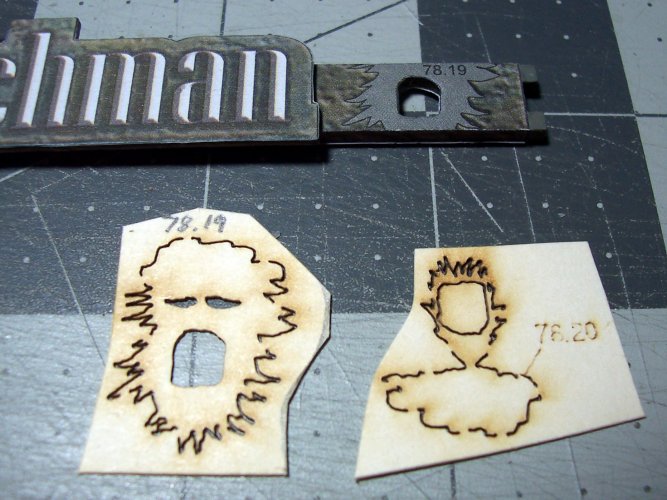
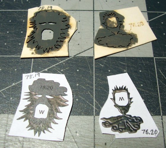
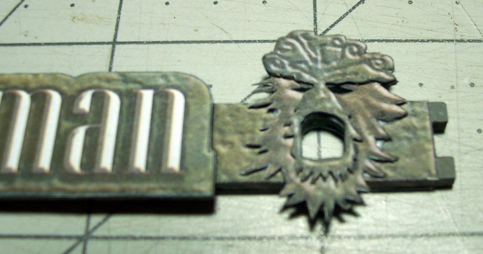
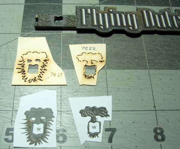
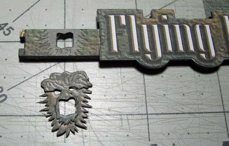
You may have thought, "I have some spares of these faces, so I will toss them out!" That would have been a terrible mistake! They are also used on the stand for decoration.

018.JPG

Start off by giving them a base-coat of gray, and remember how you built them way back when for the sides of the ship? Come on now, it wasn't that long ago, was it? :hammerhead:

019.JPG

They look good in place on the sides of the stand!

020.JPG

The other side is slightly different so be careful! Look at the mouths to see what I'm on about.

021.JPG

Now, the left side mouth installation.

022.JPG

The "feet" of the stand are next. These have a 4 layers each to give them a nice thick width.

023.JPG

The color veneer just encapsulates the foot.

024.JPG

Paint the completed card foot gray firstly.

025.JPG

Okay, now we can start putting all the pieces together :loudspeaker:

026.JPG

The feet are first on the ends.

027.JPG

Just ensure that they are nicely centered on the ends. I measured it all just to be sure. Now, test the ends for a nice, snug fit with the tabs before gluing the 2 sides to the end. Eyeball them to make sure they are true.

028.JPG

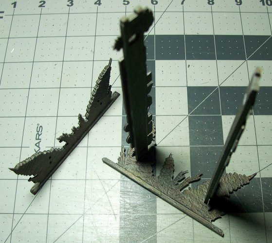
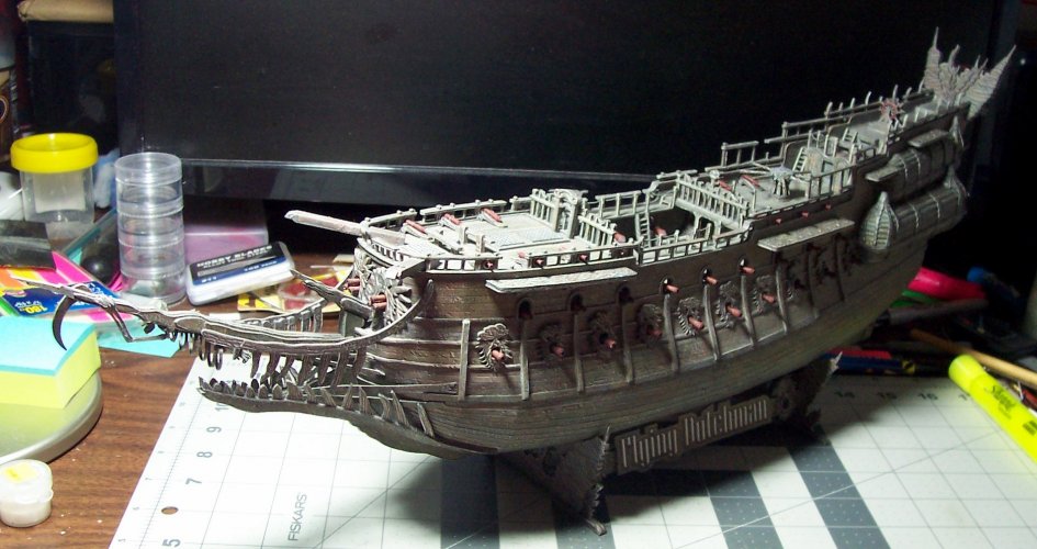
That's it! The stand is all nice, and ready for your ship!

029.JPG

I just had to make sure it fitted nicely.

030.JPG

It does seem to look pretty nice?

031.JPG


The Foremast Construction​


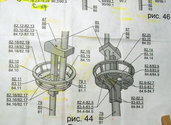
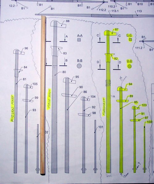
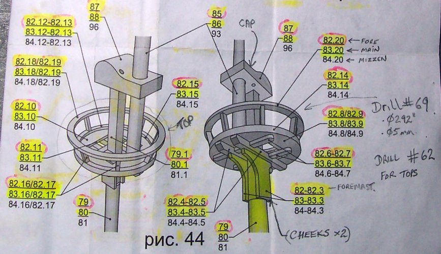
This is a milestone as we ow start on building the masts for the ship. This is the detail for building the tops, caps, cross-trees, trestle-trees, depicted in Pic 46 below. Wow. my plans are getting a bit worn at the edges!

032.JPG

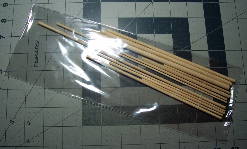
I bought the optional wooden parts kit for the Flying Dutchman ship.

033.JPG

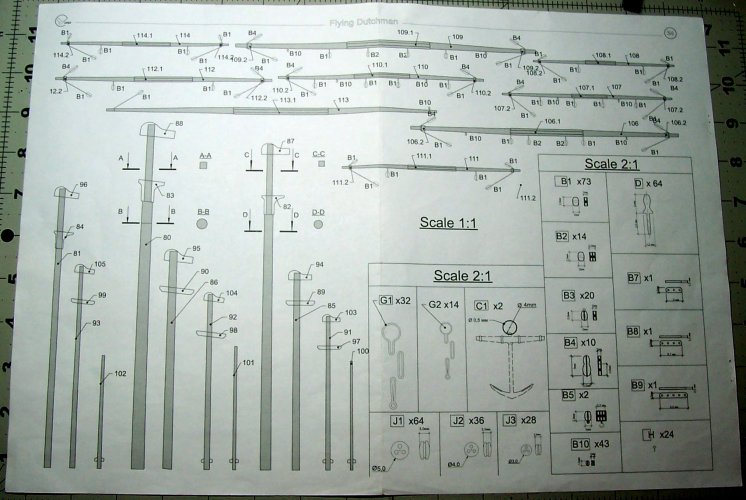
This is the plan for the masts amongst other things.

034.JPG

Next, continue to build the masts.
 

mijob

Tie designer
Staff member
Moderator
Jul 5, 2020
3,194
5,406
95
54
Netherlands
O boy a detailed ship with detauls in the details with some greeblings on the details.
I call this build trhead a nice history lesson. Thank you for building this model.
 
  • Like
Reactions: mtrappett

mtrappett

Well-Known Member
Mar 3, 2013
373
812
75
Santa Clarita, California
Ah, the weather's starting to get hot here again :realmad: It is California though, and used to be a desert. No air conditioning though making it nasty!

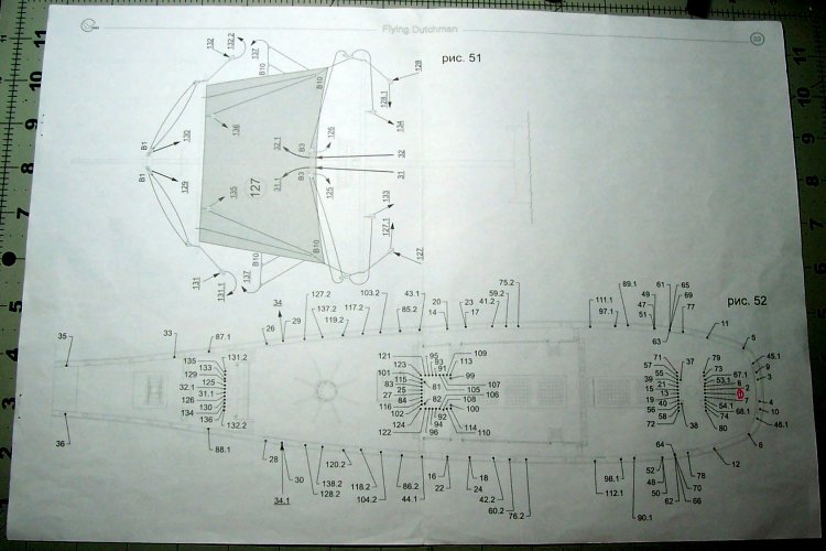
I have to say it! It looks like it was never anticipated that the build would progress to the yards, and the rigging! The plans are very hard to follow for these items. Pic 51 below shows the mizzen sail, and a plan view of the hull showing the running rigging layout for the fife rail and belaying pins. That's to come own the line :eek::biggrin:

035.JPG

There are a lot of mast pieces so organization is essential!

This is a man-o-war ship used to bring down the foes. There is a standard layout for the sails with the mizzen at the stern, main amidships, and fore forward. I have been looking forward to this part of the build! It looks like quite a challenge :yesyes:

The parts of the masts are made of very thin paper, and would not have enough strength alone. Therefore, its almost certain that a stronger base for them is needed. There is a kit for the Flying Dutchman paper model which I decided to get. The pieces of dowel are quite soft and appear to have been carved to shape in a rough fashion :sadno: I wouldn't recommend getting these! I looked at the online pic, and it appeared that they were stained, and machined to shape for each one. Sadly, I was told that they were no longer available when I ordered the model from the Ukraine. I think they must have cobbled together a bunch of dowel pieces to satisfy the order? I used a few of them, but I mostly just used my own dowel pieces left over from old projects. Live and learn I guess?

036.JPG

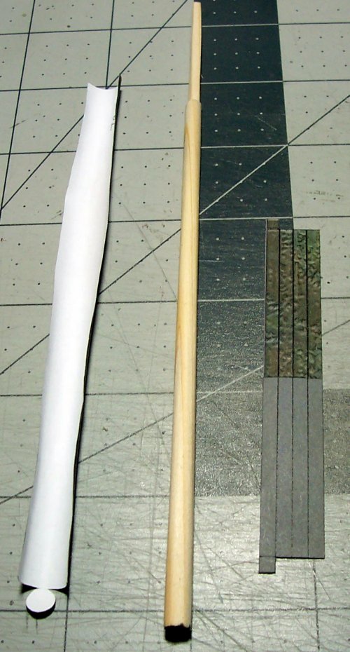
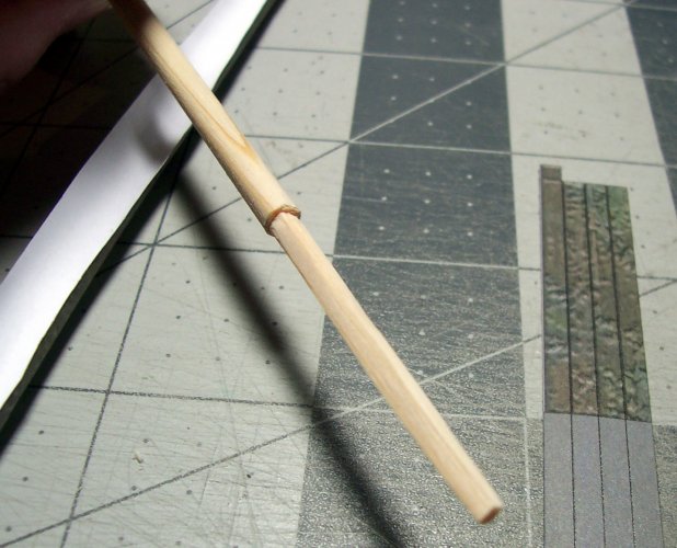
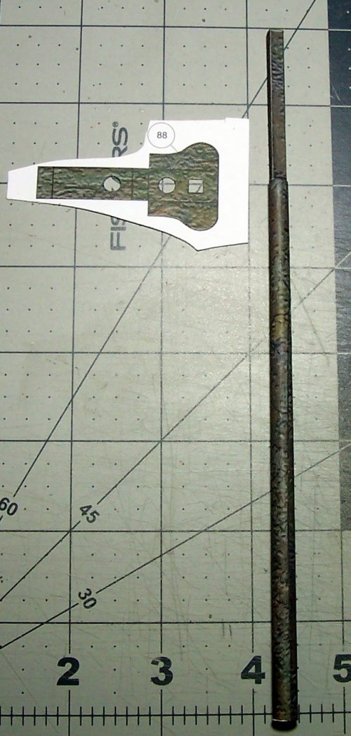
There is some shaping needed according to the plan. I use the paper parts as a guide for shape and size requirements. I cut the "ears" off the paper veneers for the top and bottom ends of the masts as they are not needed.

Notice the square section that protrudes at the top of this which is the foremast. This will provide a nice strong support. I also cut off the base piece of the card square insert for the masts, as they are also no longer required.

037.JPG

A little tricky! You have to practice your whittling skills here :yesyes:I recommend marking the wood continuously with pencil as a guide. Then needle files, and sandpaper.

038.JPG

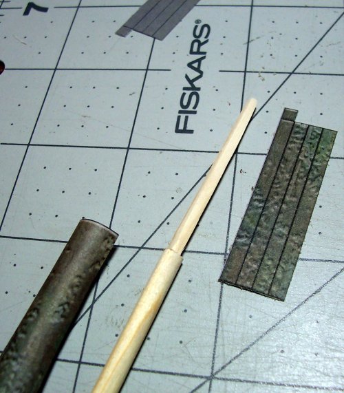
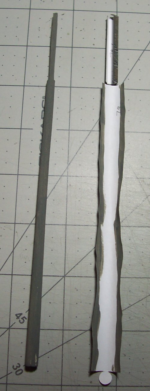
The wood gives the strength, and the paper the color.

039.JPG

I like to paint the mast parts to avoid any light peeping through the butt joints for the edges.

040.JPG

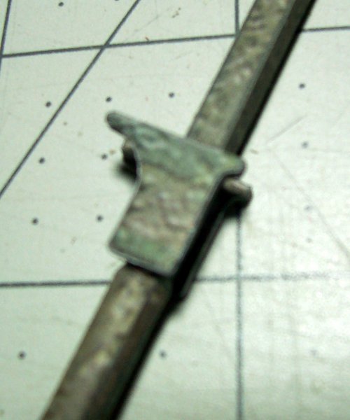
These are the cheeks :mooner: No, the other cheeks!

They will support the tops on the mast.

041.JPG

They go at the joint of the round and square sections.

042.JPG

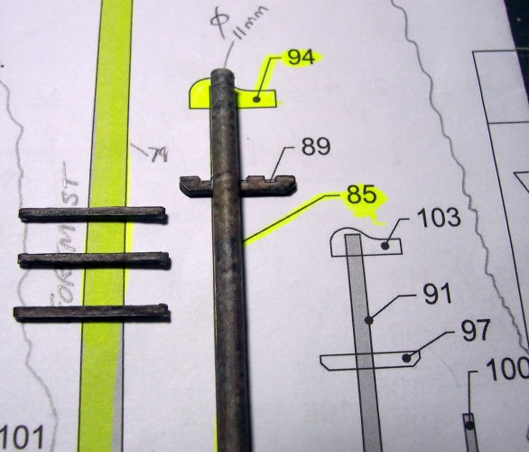
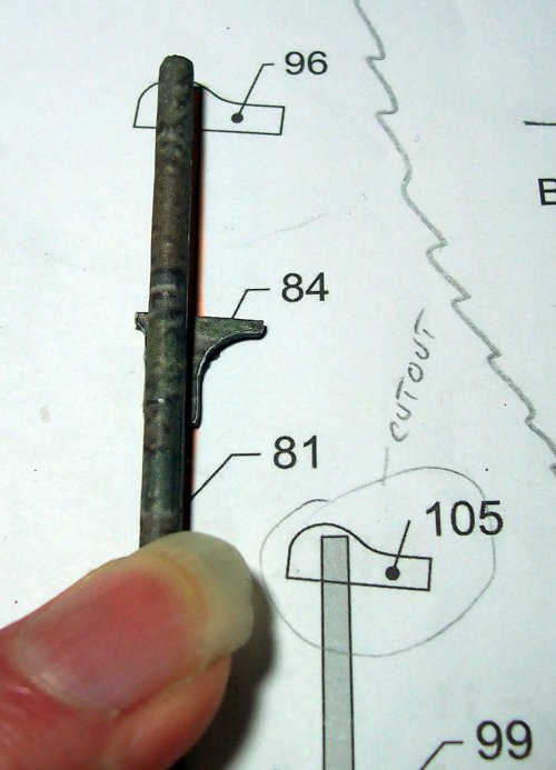
Part #87 is the cap. This goes on the top of the lower mast sections.

043.JPG

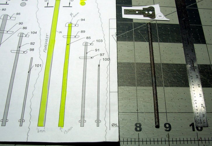
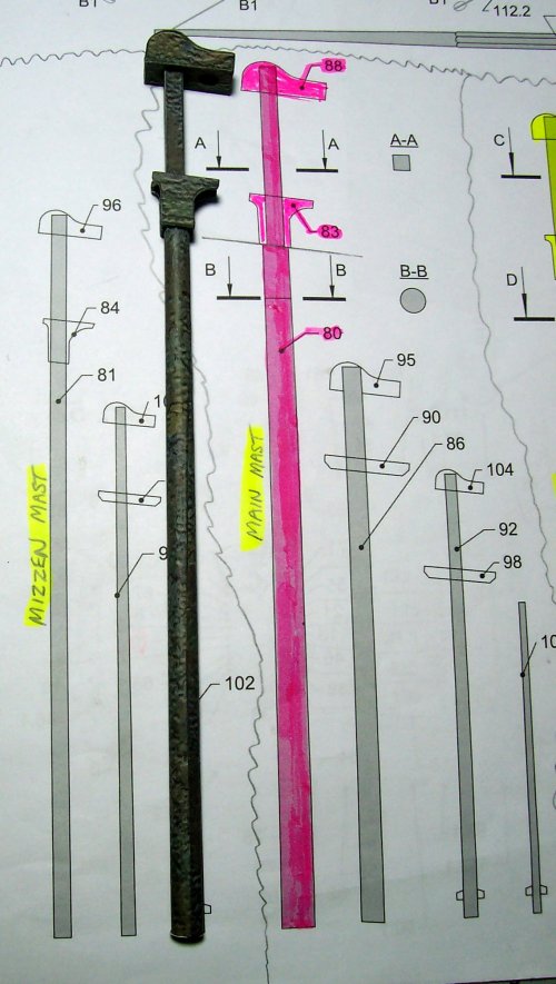
The plan is useful as it provides a 1:1 scale for the masts.

044.JPG

The lower foremast section completed.

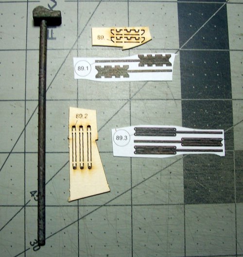
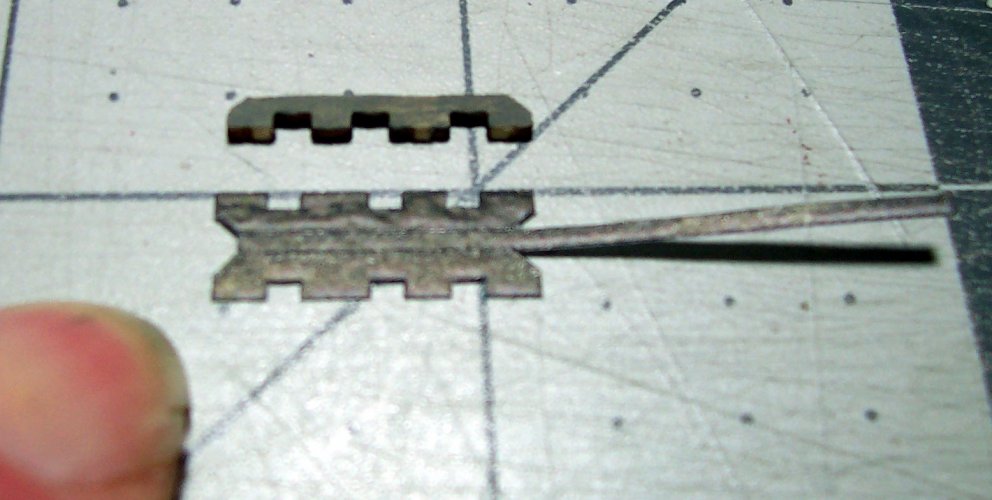
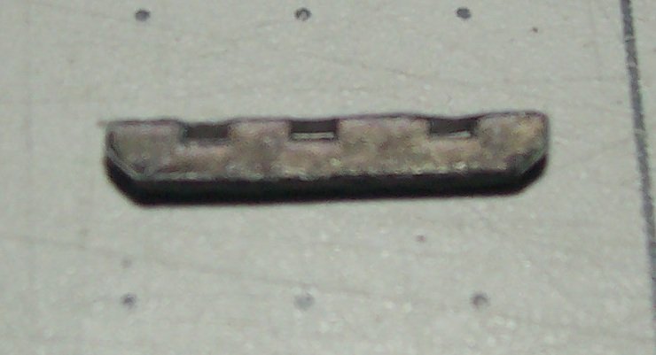
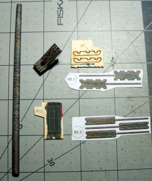
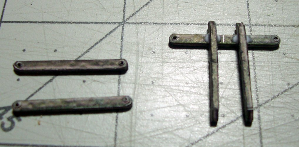
Parts #89.xx are for the cross-trees, and trestles shown below. Make sure to drill the holes for the rigging in the ends of the cross-trees afterwards. A hair-drill is needed.

045.JPG

These are the trestles. They are in pairs typically.

046.JPG

Just snip the paper veneers, at the upper surface of the cutouts.

047.JPG
 

zathros

*****SENIOR ADMINISTRATOR*****
Staff member
Administrator
Moderator
Apr 5, 2013
13,502
9,551
228
You'd better have this ship in a will to someone, family members will be fighting over it when you pass. ;)
 

mtrappett

Well-Known Member
Mar 3, 2013
373
812
75
Santa Clarita, California
Yes, I have been enjoying this thread and seeing the work that you have been putting into this project! Thank you very much for sharing this with all of us! Like I had mentioned earlier, this thread is a perfect guide for anyone who is interested in trying their hand at this model!
I'm very happy that it is of interest, and that is the driving force behind this thread for me. I'm find I am learning so much myself too from others, experimentation, books, videos and so on. Thank you again for taking the time to respond! :)
 
  • Like
Reactions: zathros

mtrappett

Well-Known Member
Mar 3, 2013
373
812
75
Santa Clarita, California
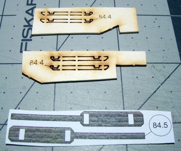
This is the continuation of building the masts, caps, tops, cross-trees, and trestles.

Currently, this is focused on the foremast at the stem (front) of the ship.

001.JPG

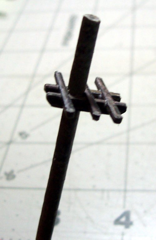
The cross-trees and the trestle-trees can be seen for the foremast in the picture below.

003.JPG

Next section of the foremast.

004.JPG

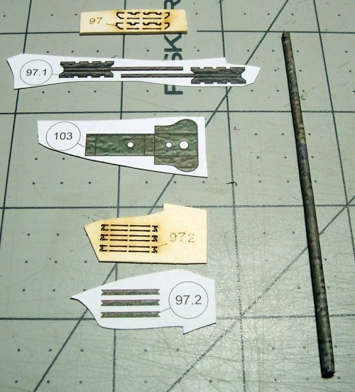
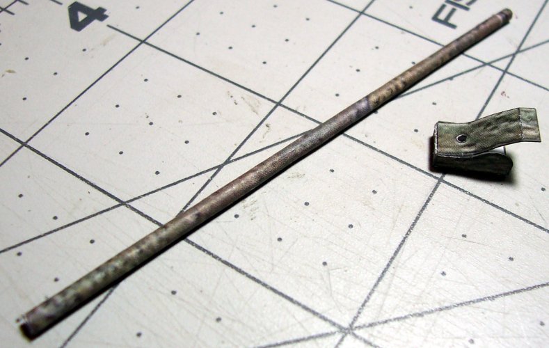
The cap part #103.

005.JPG

This is the mid-section of the foremast. The cap is almost complete just needing to glue the flap in place.

006.JPG

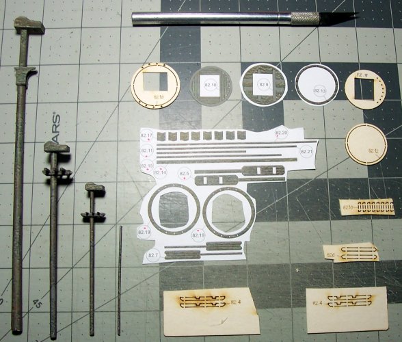
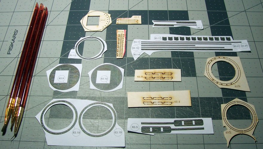
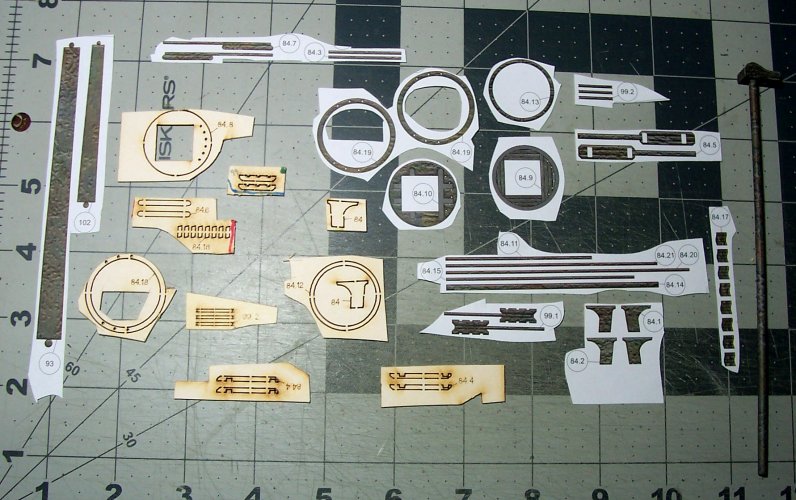
These are all the parts for the top, and cross-trees, and trestle-trees for the foremast. These will fit on the far left, lower section of the mast on top of the cheeks.

007.JPG

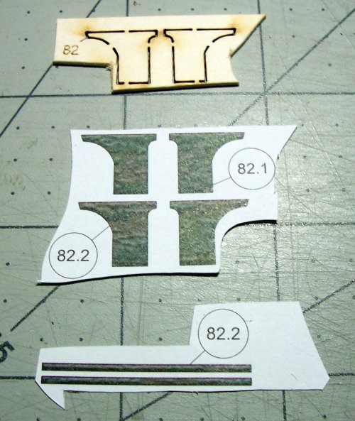
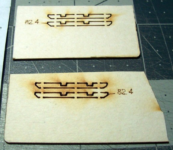
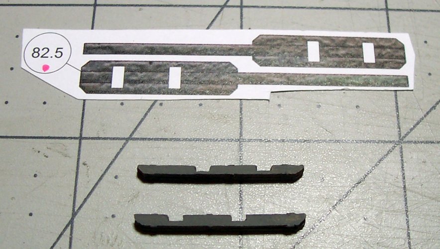
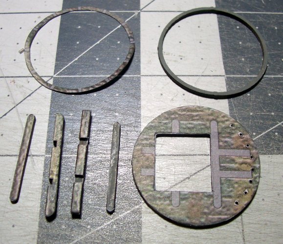
Starting with the trestles construction, parts 82.4. These are each laminated from 2 pieces (4 in total).

008.JPG

After painting them gray, then time to add the color veneers.

009.JPG

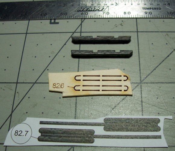
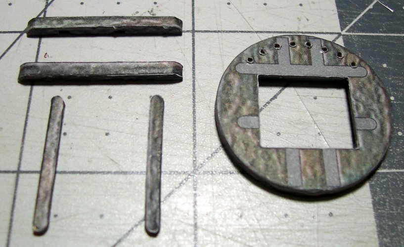
Next, the cross-trees, called cross-trees because they go across from side to side of the ship. Parts 82.6-82.7

010.JPG

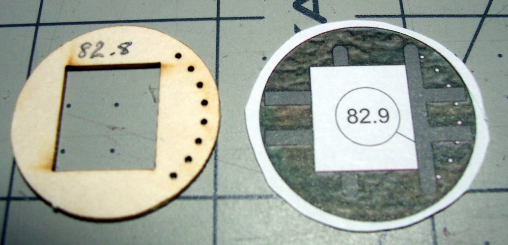
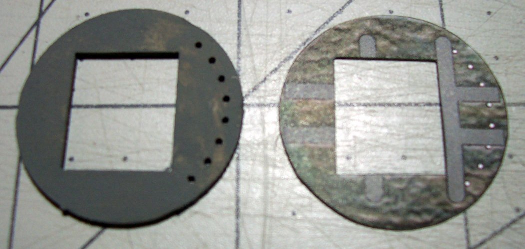
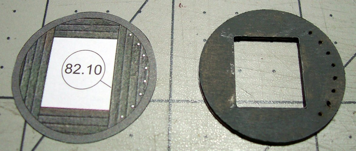
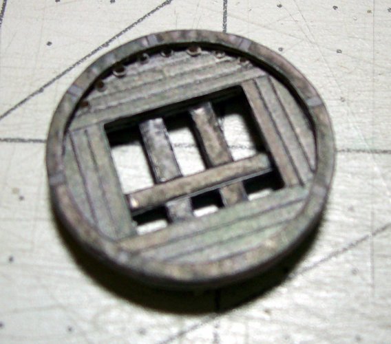
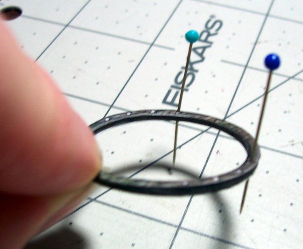
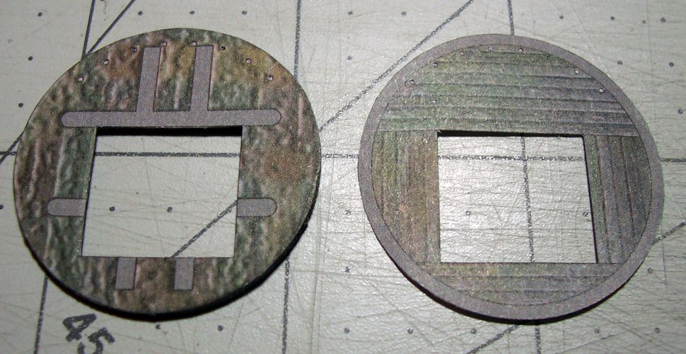
This is the base for the top. Cut out the square middle section marked in white. The trees are highlighted for correct orientation. Also, make sure to use a pin to mark each of the holes needed for the rigging. This makes it easier to make sure you have it aligned correctly. Parts 82.8-82.9

011.JPG

A quick brush over with gray paint to seal the card layers at the edges. The holes for the rigging are larger for the heavier rope.

013.JPG

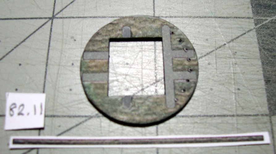
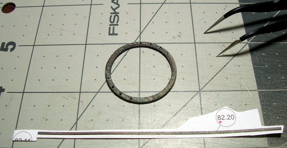
Glued as one. Also, drilled the holes through to enable easy passage of the rigging thread. 82.11 is the ribbon color veneer that goes around the edge of the top.

014.JPG

Now, flip the base over, and start work on the upper side.

015.JPG

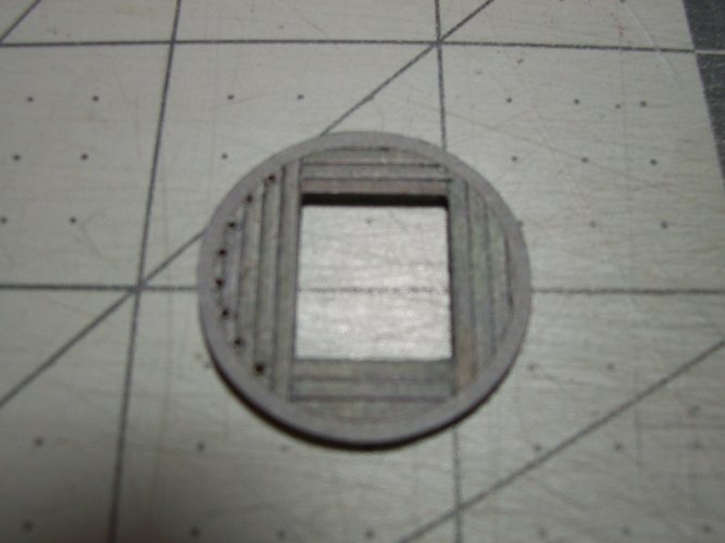
I scored the planking into the base to give a nice realistic effect even though it probably wont be seen unless you know what to look for!

016.JPG

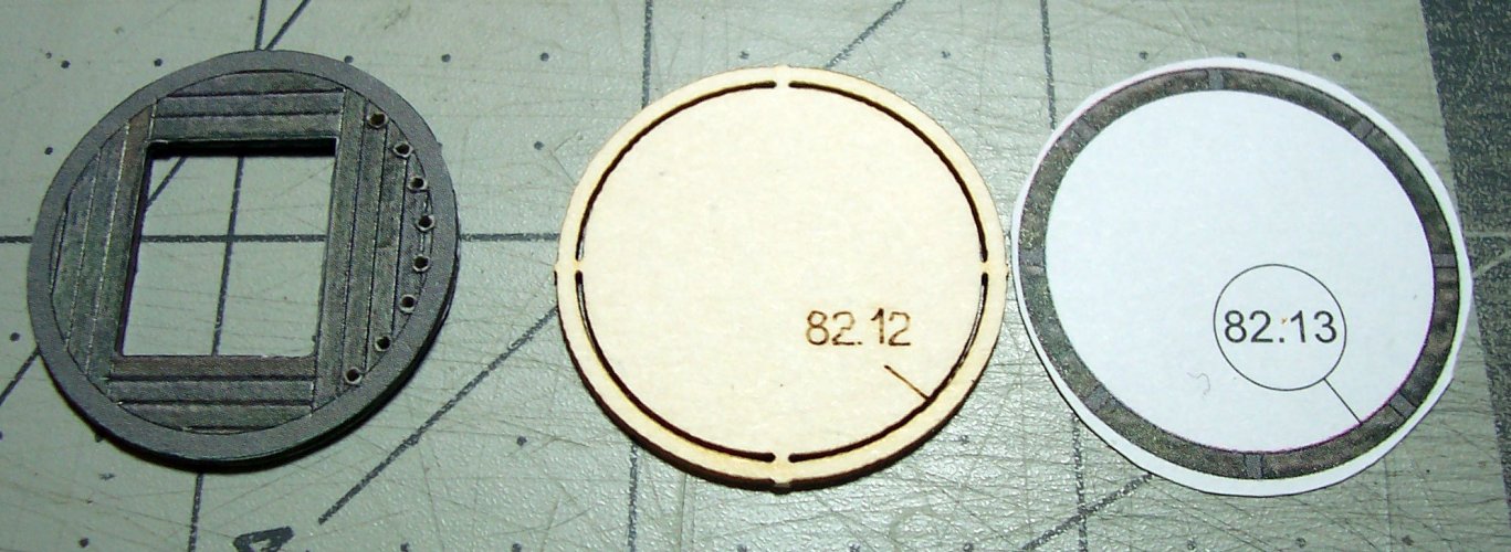
Time for he rim of the base. Parts 82.12-82.13

017.JPG

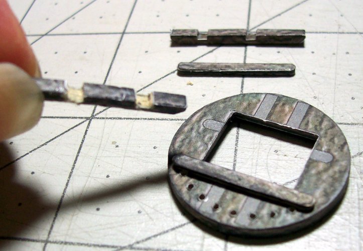
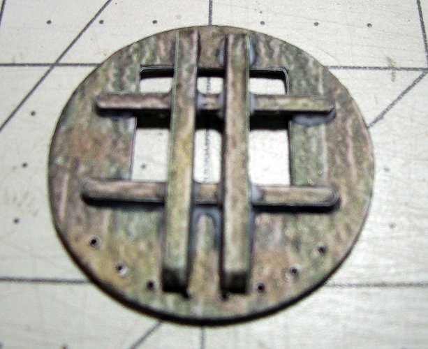
Glue in place the cross-trees and trestle-trees on the highlighted areas of the base.

018.JPG

I had to modify the trestle-trees cutout locations which go over the cross-trees. They were too small. Use of the scalpel, and needle files was required. If this is not done, the whole assembly will be wonky sitting on the cheeks of the mast eventually :sticktongue::headbange: Go easy though as the base of the cutouts will finish up paper thin!

019.JPG

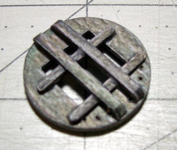
Cross-trees and trestle-trees in place. Note that the holes for the rigging are very close to the trees.

020.JPG

This is the flip side showing the rim in place. I use a darning needle with a little thinned white glue on the tip in each rigging hole, and twist it a little. This provides a nice smooth run for the thread.

021.JPG

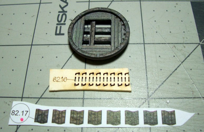
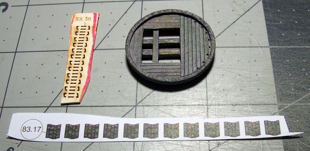
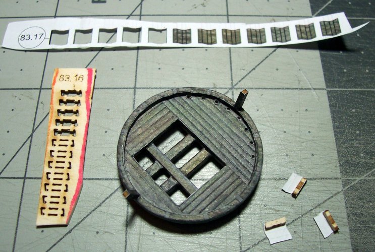
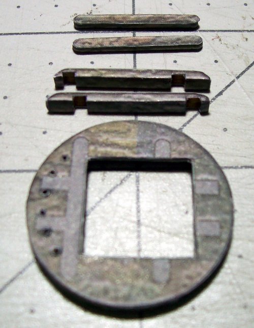
Parts 82.16-82.17 are the ribs that support the rail of the top. Again, the position for each of these are highlighted on the base rim.

022.JPG
 

mtrappett

Well-Known Member
Mar 3, 2013
373
812
75
Santa Clarita, California
Continuing with the foremast, caps, trees, and tops assembly.

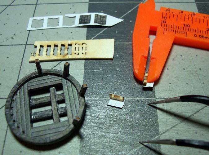
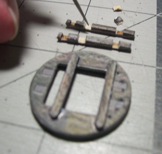
The ribs for the top are very tiny. They also have to be encapsulated inside the color veneer. This gives them additional strength too.

023.JPG

Get all the ribs just tacked in place on the top's base rim.

024.JPG

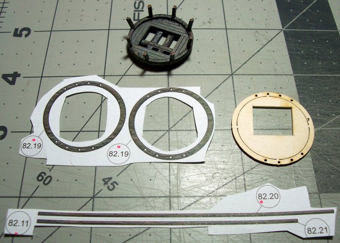
Now, build the top rail. I used a few pins to keep the parts aligned properly as the glue dries. Just go around a bit at a time with the glue to ensure its accurate.

025.JPG

Again, drill the holes through all the layers for the future rigging locations. Part 82.20 is the color veneer ribbon that goes around the edge of the top.

026.JPG

Here is the completed foremast. I suggest not gluing this to the ship or together as it will make it easier for the rigging later on.

027.JPG

Moving on to the mainmast.

028.JPG

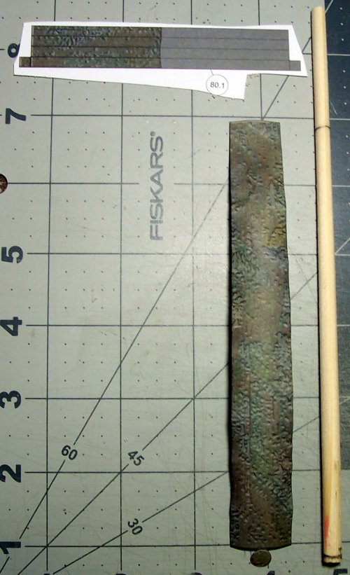
Trim off the not needed gray section of part 80.1. This is based on the use of wooden masts.

029.JPG

Note the hand-carved square-section of the mast to the right of the picture below. Part 88 is the mainmast cap.

030.JPG

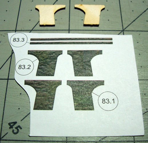
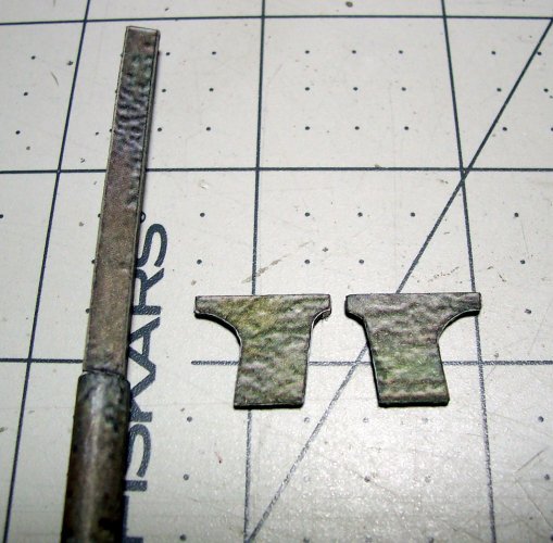
These are the lower mainmast cheeks.

031.JPG

The cheeks sit at the joint of the round and square sections of the mast. Also make sure they are angled according to the plan.

032.JPG

The parts laying next to the plan's layout for verification.

033.JPG

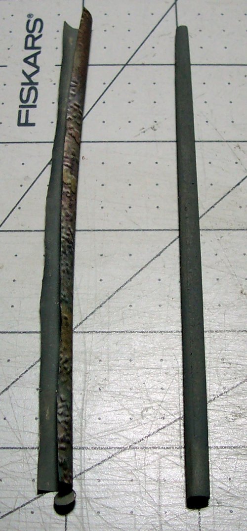
This is the mid-section of the mainmast. To the left is the veneer color "skin". Grind the dowel so the color veneer fits perfectly on the dowel. Then apply the glue to the dowel and wrap the color veneer around the dowel/mast. Next, roll the mast on a flat table to ensure it is smooth and there are zero wrinkles.

034.JPG

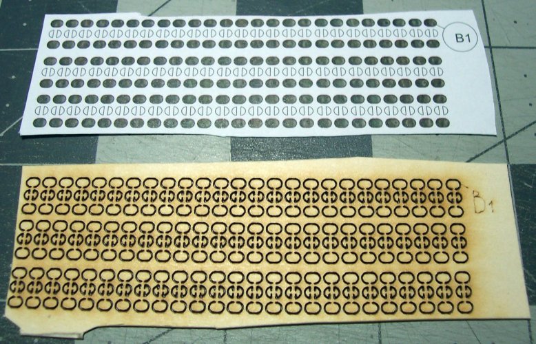
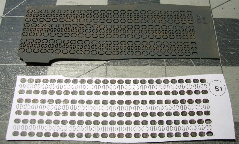
I decided to break-off for a bit to explore the fittings options for the model. Below are the single sheave blocks B1 for use all over the ship. I made 3 of these in an evening. They are EXTREMELY small, and quite delicate. Each block which is smaller than a bed-bug is comprised of 8 parts, and there are 73 of these needed :OOPS: Yep, 73 of these bad boys! That is only the B1's then there are the double blocks B2 which needs 14, B3 which needs 20, fiddle blocks 10 needed, triple sheave blocks with hooks B5 2 needed, and B10 even tinier single blocks which 43 are needed! The holes in these home-made blocks also need to be drilled a bit for allowing the finest thread to go through. There are also no grooves in the blocks for the thread to be tied around it! So, I decided that although these could be used in an emergency, I needed to get "real" blocks for the job!

035.JPG


036.JPG

Go very easy on drilling the holes through for the cross-trees! They are super-delicate!

037.JPG

Use a nice glue gusset with Elmer's Extreme thinned a bit to get it to flow into the joints.

038.JPG

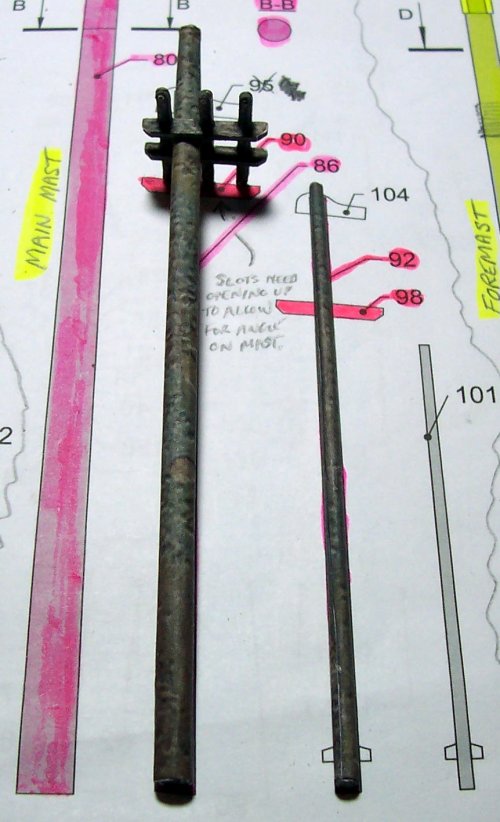
Use the plan to correctly place the trees assembly on the mast.

039.JPG

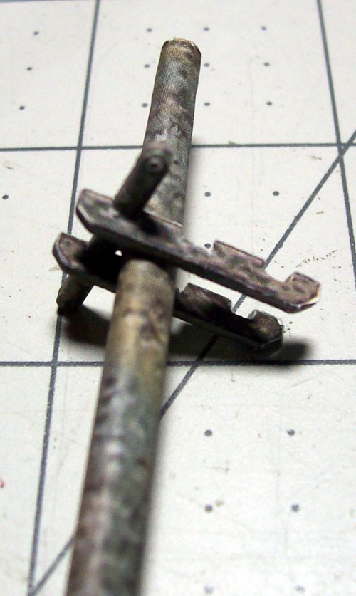
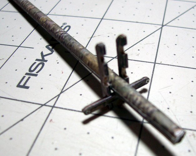
This is the assembly sequence that I found works the best for the trees. I did have to modify the slots for the cross-trees to get them to fit.

040.JPG

The plan is very useful for checking the location of items and is full scale so you can place the parts to verify anything if needed! Just like building my old model airplanes :drinksmile: There are so many parts too that its easy to get overwhelmed so I use different color marker pens to mark-off what I have worked on.

041.JPG

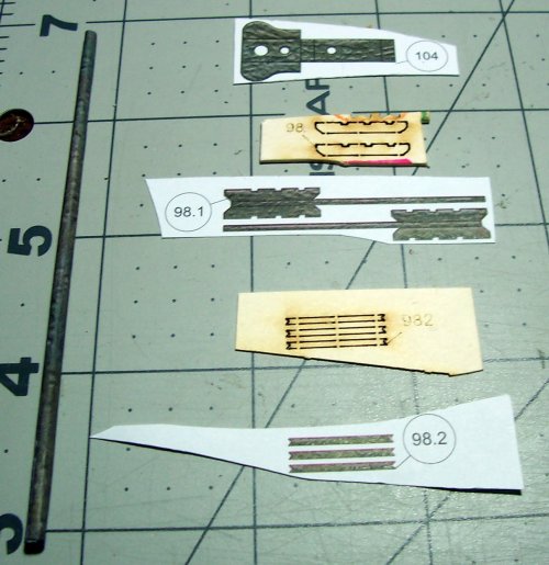
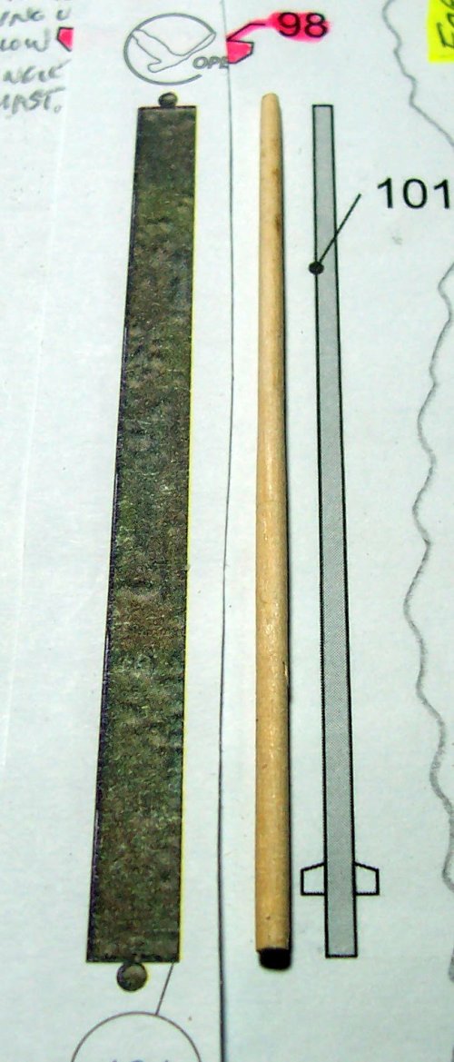
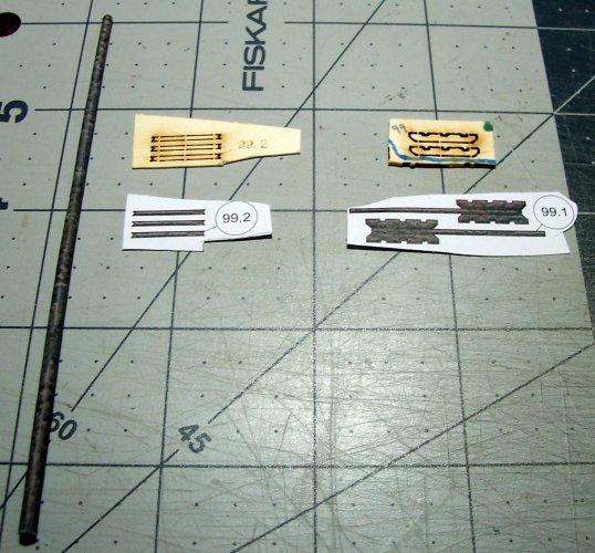
The fore topmast assembly. The cap 104, and trees. Note the grooved ends of the cross-trees parts 98.2. This is to enable the rigging to rest in the grooves.

042.JPG
 
Last edited:

zathros

*****SENIOR ADMINISTRATOR*****
Staff member
Administrator
Moderator
Apr 5, 2013
13,502
9,551
228
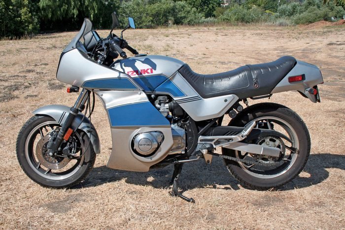
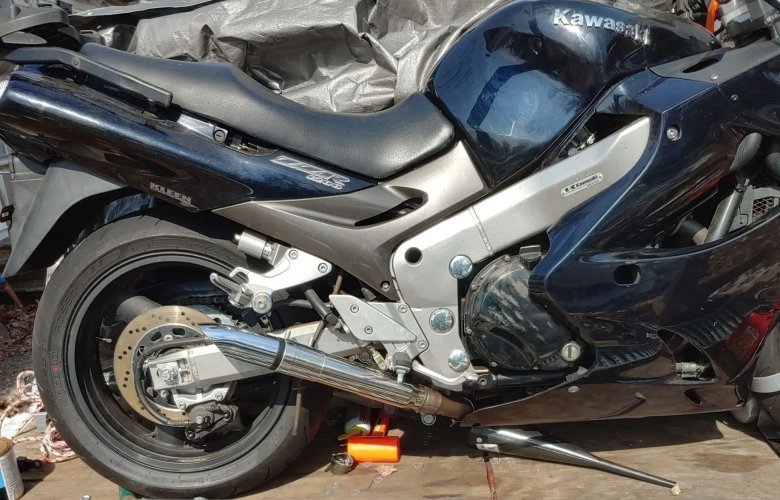
I'm posting a few pictures of my bikes to show "mtrappett", there was no other way to.

My GS750ES is the first pic the second is my ZZR1200 (my year Kawasaki only had the small ZZR 1200 decal on it, it's otherwise just dark blue, with the custom exhaust I made, the 3rd is the ZZR1200 with the stock nuclear reactor 54 lbs exhaust cans. My new pipes weigh around 8 lbs. each side. I have to touch up that clutch cover, the guy dropped brake fluid on it and never took it off. Like I stated, a Kaw 2004 ZZR1200 with only 4394 miles on it, crazy!! (It needs a good waxing). The exhaust I made is fully baffled on the inside with high temperature wadding, and a baffle system I welded in, it only looks like straight pipes, it sounds awesome!! :)

GS750ES w Lockhart Lowers.jpgzzr1200-exhaust mod.jpgKawasaki-ZZ-R1200c stock.jpg
 
  • Like
Reactions: mtrappett

mtrappett

Well-Known Member
Mar 3, 2013
373
812
75
Santa Clarita, California
I'm posting a few pictures of my bikes to show "mtrappett", there was no other way to.

My GS750ES is the first pic the second is my ZZR1200 (my year Kawasaki only had the small ZZR 1200 decal on it, it's otherwise just dark blue, with the custom exhaust I made, the 3rd is the ZZR1200 with the stock nuclear reactor 54 lbs exhaust cans. My new pipes weigh around 8 lbs. each side. I have to touch up that clutch cover, the guy dropped brake fluid on it and never took it off. Like I stated, a Kaw 2004 ZZR1200 with only 4394 miles on it, crazy!! (It needs a good waxing). The exhaust I made is fully baffled on the inside with high temperature wadding, and a baffle system I welded in, it only looks like straight pipes, it sounds awesome!! :)

View attachment 202845View attachment 202846View attachment 202847
Great looking machines Zathros! I always loved the Suzuki GS750ES. My friend where I worked in the UK had the English version of it.

The Kawasaki ZZR1200 is a real beauty for sure! It looks totally immaculate! I would love to hear the sound of those exhausts! I much prefer the pipes you designed and fitted as they seem to support the lines of the bike better. WOW, less than 5k miles on it too! These bring back some great memories from back in Birmingham riding my motorcycles. Thing I really love about these motorcycles, is that there are no cars that can touch them for performance. No Italian or otherwise sports cars. These will leave them in the dust. When you are riding one of these, you are like a eagle in flight.
 
  • Like
Reactions: zathros

mtrappett

Well-Known Member
Mar 3, 2013
373
812
75
Santa Clarita, California
Continuing on with the masts assemblies.


043.JPG

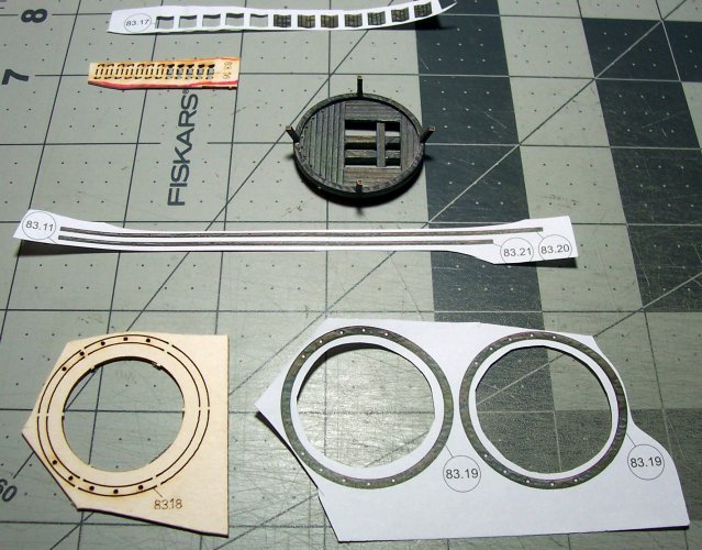
This is the lower main mast and top (all parts #83.xx is for main).

044.JPG


045.JPG


047.JPG


048.JPG


049.JPG


050.JPG


051.JPG


052.JPG


001.JPG

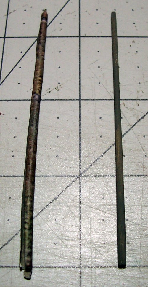
I found that my X-Acto razor-saw worked great for cutting the masts to length after rolling the dowel around on the work surface while scoring the position.

002.JPG

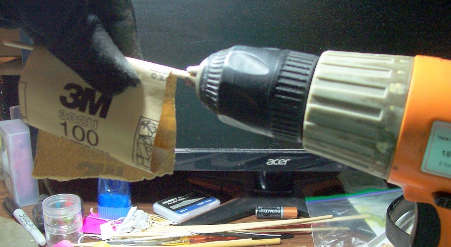
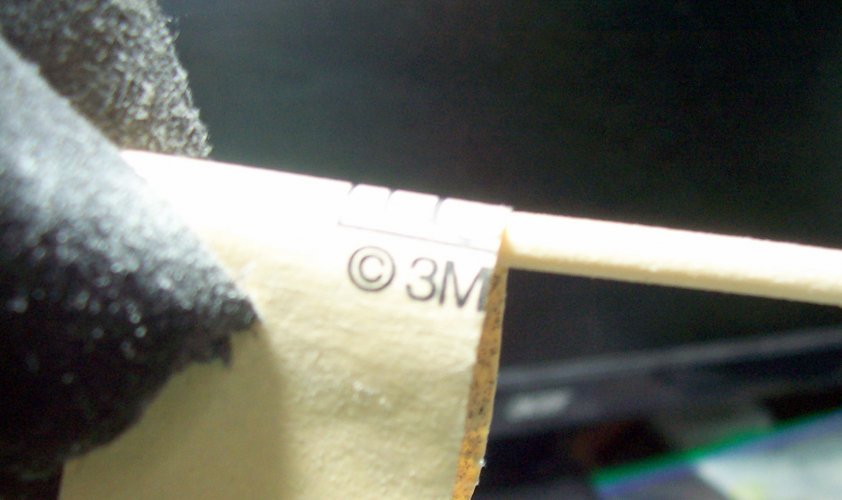
Some 100 grade sandpaper to get the desired taper on the masts. The drill makes it more accurate. The sandpaper gets super-hot so the gloves protect the fingers from getting burnt.

003.JPG


004.JPG

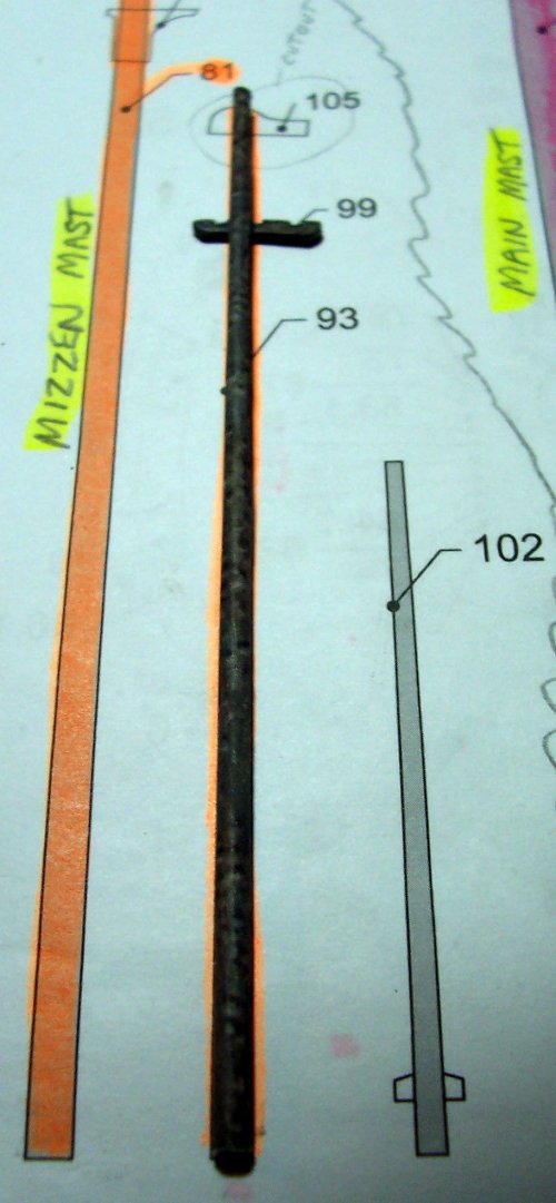
Next, the mizzen lower mast, parts 84.xx

005.JPG


006.JPG

The full scale plane helps for checking the position of components.

007.JPG


008.JPG


009.JPG


010.JPG


012.JPG
 

mtrappett

Well-Known Member
Mar 3, 2013
373
812
75
Santa Clarita, California
Continuing with the masts construction for the Flying Dutchman ship model.

The trestle trees cutouts had to be opened up a bit for the cross trees.


013.JPG

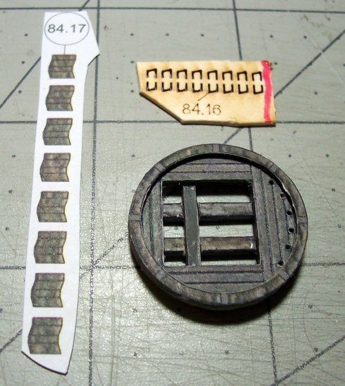
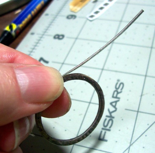
These are tiny to work with but they provide the railings/ribs for the tops.

014.JPG

Applying the ribbon edge color veneer to the top rim.

015.JPG

That concludes the basic masts construction. There are additional steps, but they will be included when the time comes.

The Ship's Yards​


The yards or spars also need to be ground from wood to enable greater strength for adding anything else desired such as the rigging or sails. The similar procedure as used for the masts is required.

016.JPG

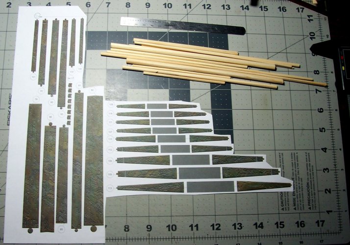
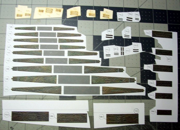
These are all of the paper and card parts provided in the kit for the yards. There is a LOT of work with these! Take some time to get familiar with the plans and fitting of parts for each assembly. Without using a wooden base for each of these, they would be very weak, and would bend and damage easily. Its interesting that the written instructions really provide zero coverage for building these at all? There's also only about one line for the masts? It honestly seems like they don't expect the builder to continue with completing the full ship? That's a little sad!

017.JPG

I used what was left over for the masts for the yards in terms of the wood stock. In most cases though, I just used my own dowel that was of a harder wood. Even though it took longer to grind the spars to shape, the extra strength with be beneficial down the line. The process of using the wood with the paper color veneer over the top, provides for a very strong piece. There is a great deal of information that is not provided (or none at all) for the masts and yards. It seems they really left it up to the builder.

018.JPG

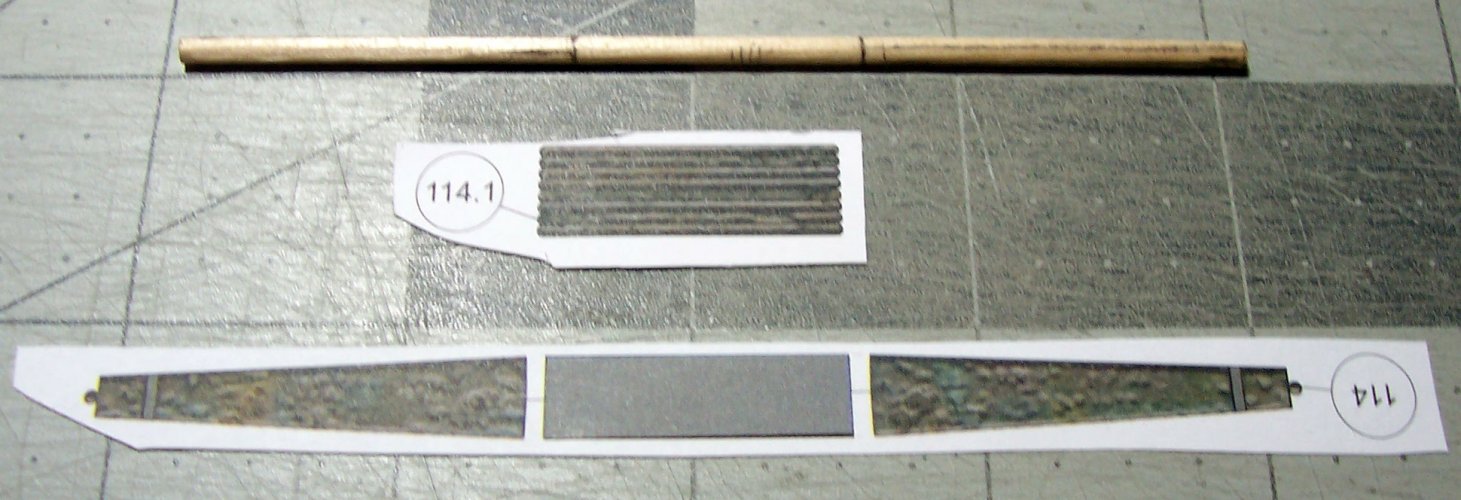
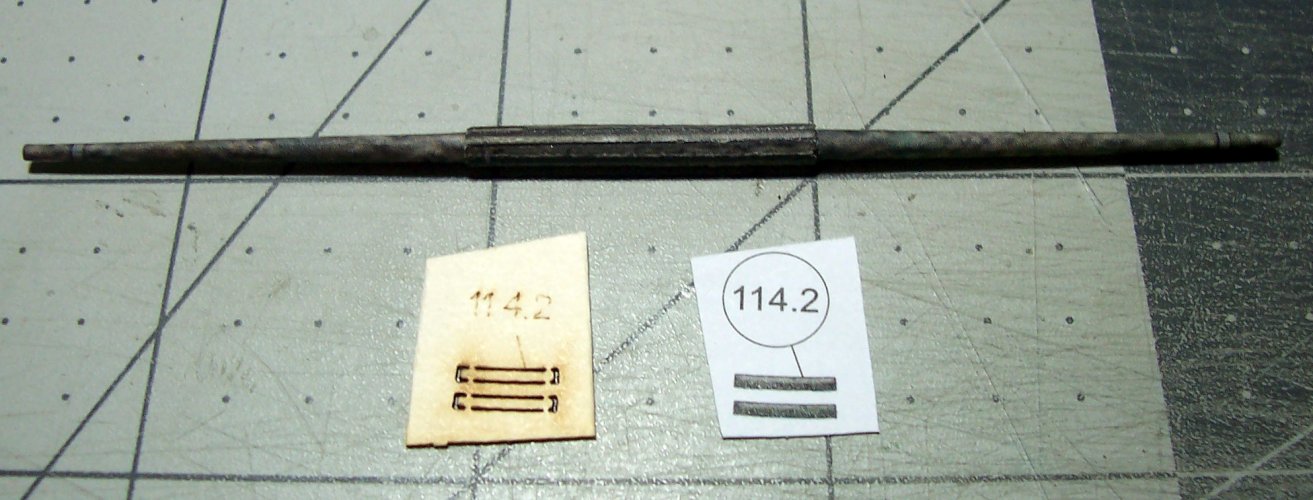
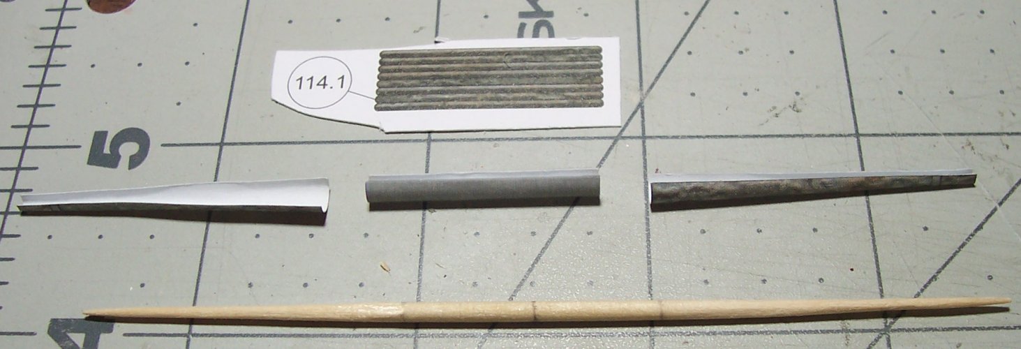
The part 114.1 is the polygon shaped wooden center section of the yard. I scored each of the plank lines to enable it to be folded to shape. This looks like they included a nice detail!

019.JPG

Here's the yard almost complete.

020.JPG


021.JPG

It now has the "polygon wooden section' in place.

022.JPG


023.JPG


024.JPG


025.JPG


026.JPG


027.JPG


028.JPG


029.JPG

These are the blocks B1 provided with the kit. Each block is comprised of 8 parts. Each is EXTREMELY tiny, and has to provide a path for the rigging thread through the middle, and around the block itself. This is very time-consuming, and doesn't give a very satisfactory result.

031.JPG


032.JPG


033.JPG
 

mtrappett

Well-Known Member
Mar 3, 2013
373
812
75
Santa Clarita, California

Rigging of the Yards​


Here is where the "rigging" of the ship really starts. It is best to complete as much as possible off the ship. The more that an be completed as separate components, the better / easier it will be to get the job done!

I found myself that I needed to get a good understanding of what each part of the rigging was called, as well as other ship naming conventions in general. This is absolutely essential to be able to follow any descriptions out there in books or online. Its a vast ocean of names, like jeers, forecastle, belaying pins, fife rails, lanyards, seizing's, futtocks, shrouds, dead-eyes, fiddle blocks, and so on. You need to get these into your head first. There is also an order to doing the rigging. You need to make sure you don't box yourself in to an area that you can't complete. Its going to be a fun-drive maties :eek::skull:hammerhead::wave:

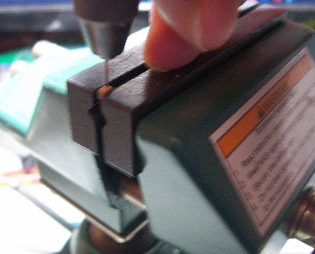
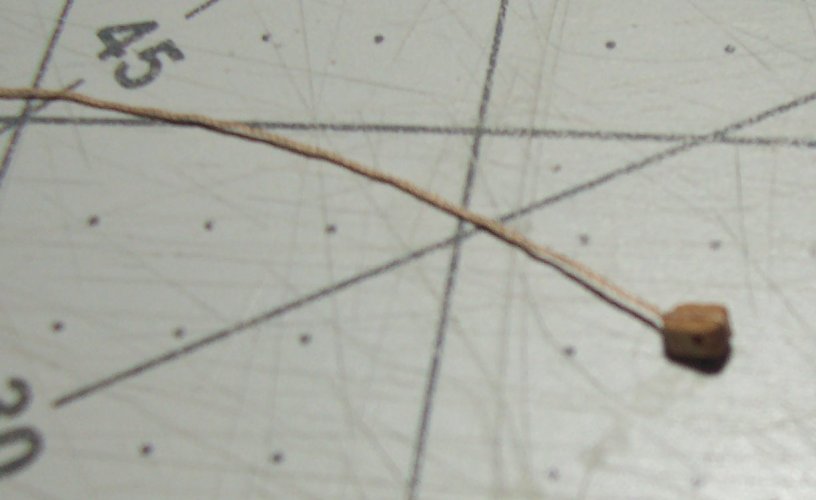
So, here I am chilling, and drilling out one of the blocks ready for rigging. This is a very tiny, oak, single block of 2.5mm long. Honestly, the paper ones provided to build with the kit are not good :sadno: They are okay as a last resort, but they have too many problems such as weakness, accuracy of shape, functionality, and so on. You have to choose your challenges well, and my advice is to buy some third-party blocks! Its totally worth it!
034.JPG

Here's one of the single blocks ready to be installed on a yard.
035.JPG

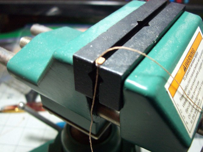
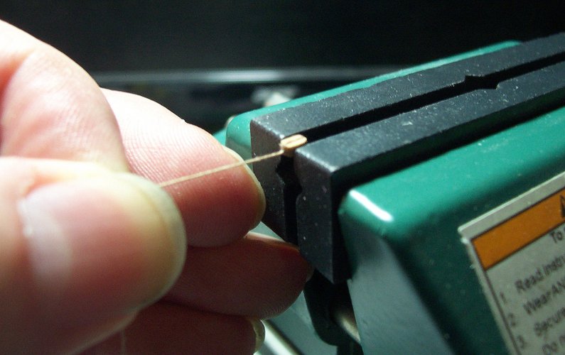
I found that gently holding the block in my ship vice works well for threading it. I always drill through the hole to make sure its clear of any wood shavings that makes it hard to thread the line. This is how I tie the line around the block. I pull it tight and use some CA glue to dap the joint. Then I trim off the one end.
036.JPG

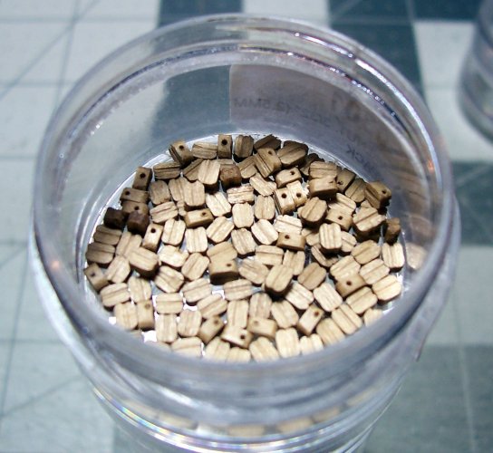
Here's my 2.5mm single oak wooden blocks to use on the yards according to the plans.
037.JPG

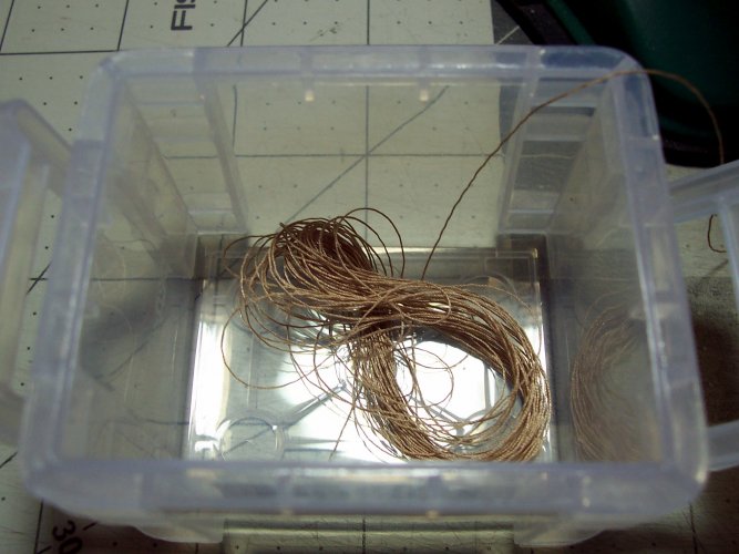
This is the rigging thread for the blocks. This is running rigging. In other words, it will not have been painted with the tar compound used on the standing rigging for other areas of the ship. It will be just bare rope, natural colored.
038.JPG

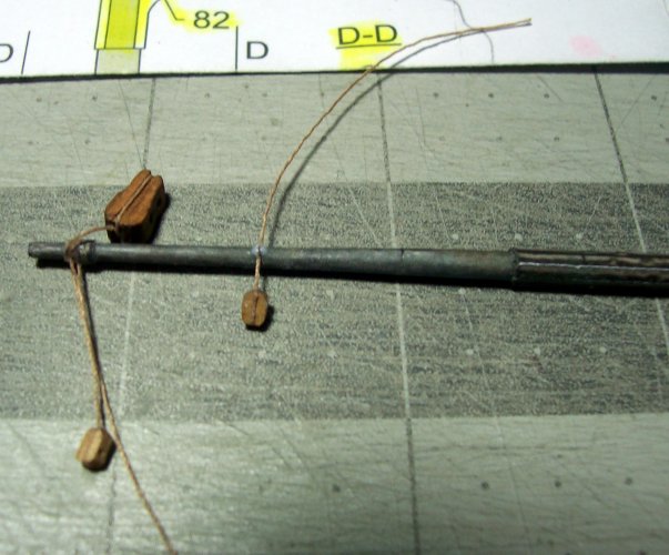
The plans indicate the correct sizes of the rigging needed.
039.JPG

On the far left of the yard, is a fiddle-block.
040.JPG

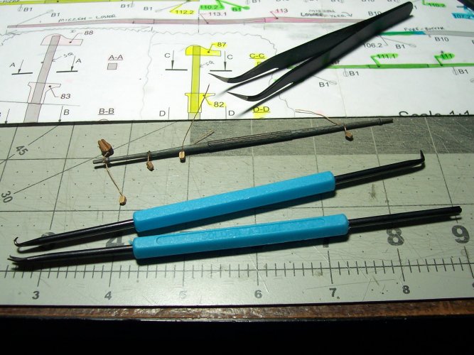
I bought a couple of ships model belaying tools (blue handles) to assist with the rigging process.
041.JPG

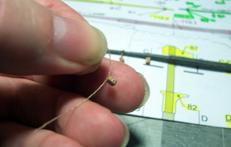
I used white glue for all the blocks on the yards. Sometimes the CA glue makes the thread too stiff to be natural.

042.JPG


043.JPG

These are the fiddle-blocks ready for usage.
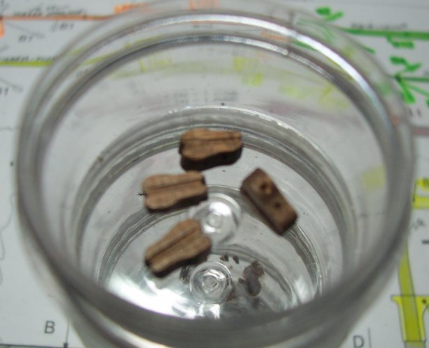
044.JPG

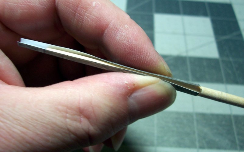
I found that rolling the spar on a flat surface is good for making sure it is nice and true.

048.JPG

The color veneer parts help making sure that the correct shape has been ground into the dowel.
049.JPG

I paint the inside of the paper veneers, and the wooden spar to disguise any slight gaps that may show.

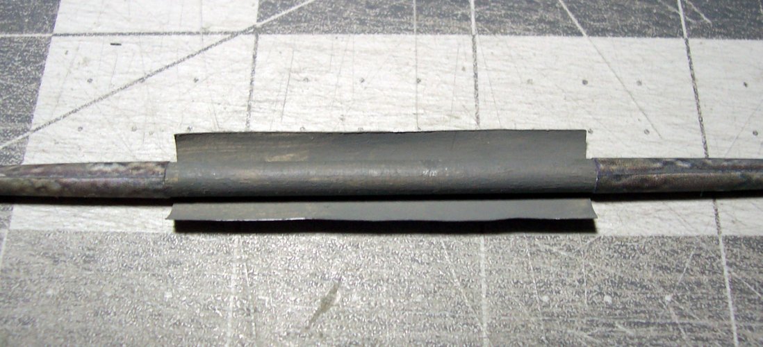
050.JPG


051.JPG


052.JPG


053.JPG


054.JPG

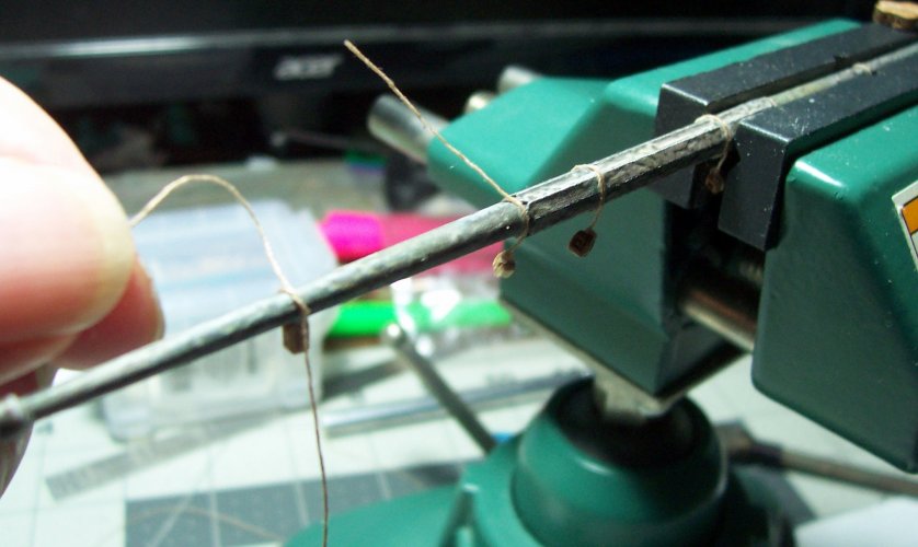
This here is a double-block. The block as it is, represents the real pulley block used on a ship. The rotating pulley inside the block is called a sheave. The blocks can either have a single, double, triple or so on set of sheaves depending on the application.
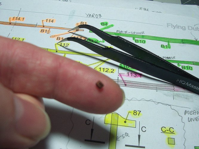
056.JPG


057.JPG
 

zathros

*****SENIOR ADMINISTRATOR*****
Staff member
Administrator
Moderator
Apr 5, 2013
13,502
9,551
228
Wow!! Real blocks. I have some wooden blocks with Brass pulleys from a 150 year old sailing ship I salvaged. I took many Bronze parts off of that ship, like pulleys, braided steel lines to wooden pulleys, one with a oval hoop, on the end of a three foot steel cable, that someone did with a Marlin Spike, then leaded. I've never seen anything like it, and the parts for a Fo'c'sle that wood was rotted on, but the Bronze fittings had a perfect patina on them. My wife asked what I was going to do with it, I told her "I don't know, but you just can't get castings like that anywhere". I would donate it to the right person making a sailboat.
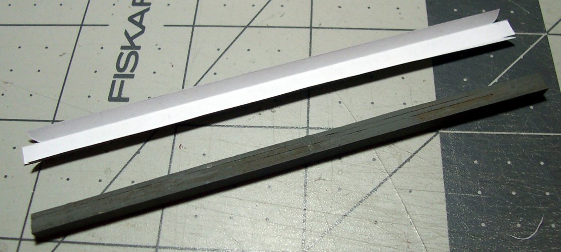
You use your electric drill like a small lathe, very cool!!
My ZZR1200 is quite a ridiculous motorcycle. New Pirelli's on it. I am putting a set of NISSIN ZX9R calipers to the front, far superior brakes. It does 80 mph in first gear, and it's a six speed. I knocked about 45 lbs. of weight modifying the bike, so now it doesn't weight too much more the my GS750ES, which is one of the finest handling bikes, almost a bit too fine, with the 16" front wheel, it seems to anticipate what you're going to do, but gets you out of trouble just as fast as you got yourself into it. I purchased that new in 1983.