time to get started on a new layout

N

nachoman

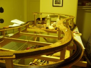
I havent gotten much new work done lately (weather turned nice and I've been doing yardwork). But, I ran across this site that shows a few photos of my prototype:

HikeArizona.COM :: Morenci Southern Railroad Photo #1 by Preston Sands on 2008-02-01

As you can see, having lots of tunnels and loops is appropriate! these photos also give me good scenery ideas. Looks like my vegetiation is going to be prickly pear cactus, century plant, creosote bush, mesquite trees, and grasses. I have made century plants and prickly pears before - the creosote bushes and the mesquite trees may be a challenge.

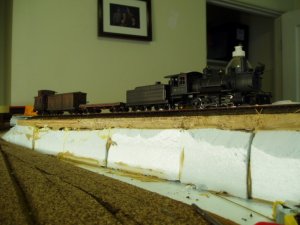
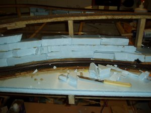
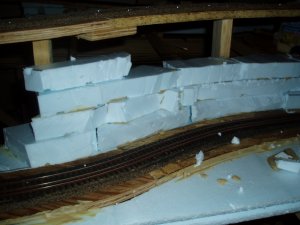
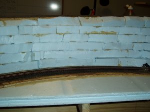
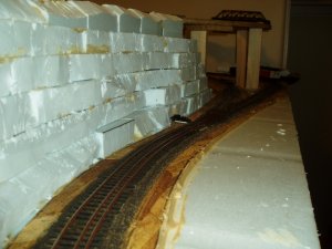
The terrain is semi-consolidated congomerate. I have made hard rock and sedimentary rock before, but this conglomerate may require a new technique. I was thinking of using layered foam for the basic landform, and coating it with some kind of sand/glue mix to give it texture.

I wish I had enough room to show the bridge across the river:)

Kevin
 

pgandw

Active Member
Jul 9, 2005
1,002
0
36
Kevin

Very much appreciate the photos.

Do you have approximate dates for the 1st two photos? Is the loco a 2-6-0? Do you know if the Morenci originally used tie plates? Weight of rail? It's hard to tell in that 1st photo.

I ask because I'm trying to get information on 1900-era practices of various narrow gauge lines.
 
N

nachoman

Fred,

The first photo is of a funeral train, and my guess is around 1910-1920. It is an outside-frame 2-8-0 built by baldwin. A similar (if not the same) locomotive was sold to the US Potash railroad in New Mexico, and then donated to a historical society in California (I think it is currently in Pomona). The flat cars with passengers are cars the railroad used to transport workers to the mines and smelters. Eventually, rooves were placed on the cars and they resembled the open cars on the Durango and Silverton train.

The second photo is probably from about 1905-1910. At some date, that trestle was replaced by a switchback. It is an ex D&RG C-16 on the trestle.

I have no idea about the tie plates or rail size. The David Myrick book "railroads of Arizona, Volume 3" covers this railroad extensively. Unfortunately, the book is rare, and I have to go to the library to see it. Because it is rare, it is housed in special collections and they won't let you check it out. Next time I go to the library, I will see if I can find that info for you.

Edit: here is a webshots album with lots of old morenci photos. Looks like no tie plates. A lot of the track you see is 20" railroad.

http://news.webshots.com/album/302498159AnqPtT?start=0

Kevin
 

pgandw

Active Member
Jul 9, 2005
1,002
0
36
Some great photographs in the collection. I love the shot of the "milk wagon". Thanks again.
 
N

nachoman

not for the weak of stomach

Here's the 3.5% grade coming together! Boy, it looks steep, but keep in mind, this is narrow gauge. I keep wondering why it needs to be so steep, but I need to gain a whole bunch of elevation as the narrow gauge line climbs over itself twice to reach it's terminus. The overall elevation gain will be about 10"!!

Kevin
 

Attachments

  • grade1.jpg
    grade1.jpg
    201.8 KB · Views: 4
  • grade2.jpg
    grade2.jpg
    210.6 KB · Views: 4

TrainNut

Ditat Deus
Sep 15, 2004
1,731
0
36
54
AZ
Neat stuffs. I look forward to more pictures. The dual gauge track looks neat. Lessee... how do I ask this... In your pictures, from left to right, you have three rails. The left rail carries both standard guage and narrow guage. The second rail carries narrow gauge only and the third rail carries standard gauge only. With that reference of the rails set up, why did you choose to put the "extra rail/the standard gauge only rail" on the outside? If you reversed the order, when running trains of either type, (from a picture point of view) you would not see any extra rails. This way, when running narrow gauge, you can always see the standard gauge rail. Was there a reason for that or a preference? I'm not criticizing your choice, just interested why you chose to do it that way.
 
N

nachoman

Take a look at the custom switch I made in the photo above. The narrow gauge diverges from the dual-gauge. If the narrow gauge was on the opposite side of the dual-gauge, the switch would have been much more complicated to build!

Kevin
 
N

nachoman

For those who havent seen it yet, I have written a short article about my layout construction for the current edition of the E-mag. Just follow the link to the e-mag from the The Gauge home page.

Kevin
 
N

nachoman

A long time with little progress -

How come it seems with everything you cross off your "to do" list, it seems like the list keeps getting longer? sign1

Anyway, between 3 weeks of fieldwork for my job and some household projects, I havent gotten much done on the layout in a month or two :curse:

I have started building a dual gauge turnout, and these things are complicated! I have a total of three to build, and I am hoping the second two will go smoother. I have also started roughing in some blue foam scenery, mainly because I need something to lay my tools on when I do trackwork :)

I will try to post some photos of the turnout construction soon, and some of the miniscule amount of roughed-in scenery i have - but my "to do" list is quite full right now :) Maybe I just need someone to come by can give me a little kick in the rear-end sign1. One of my stumbling blocks has been solved since Micro Engineering may have the micro spikes available again :):mrgreen:

Anyway, if I get two more turnouts built, I can at least run trains in a circle, and I am really looking forward to that.

Kevin
 
N

nachoman

It's been awhile since I posted new pictures. That's because I have been busy with other things, and a litttle burnt out, and havent gotten much done.

I encountered a major setback when laying the code 55 HOn3 line. After laying the first few feet, I noticed the flanges on my wheels were hitting the spikes. The micro-engineering micro sized spiked were unavailable at the time, and making my own spikes out of wire did not work that well, because the homemade spikes were too smooth and worked their way out of the ties too easily. Eventually, I had to wait until micro engineering micro spikes became available.

I have about the first 8 feet of the narrow gauge branch laid now, and have just tested it for the first time tonight. If it looks steep; it is. The grade is 4%, and 2-8-0 #3 seems to be able to pull about 3 cars and a caboose.

You can also see the start of my blue-foam scenery, and notice that the dual-gauge rail yard at the bottom of the hill still lacks track.

Kevin
 

Attachments

  • layoutgrade.jpg
    layoutgrade.jpg
    137 KB · Views: 6
  • layoutgrade2.jpg
    layoutgrade2.jpg
    182.3 KB · Views: 3
N

nachoman

Thanks for that little fact, Triplex. Most records I read say the a typical Morenci Southern train was 3-4 cars head ing up grade, so it seems I am spot-on with the prototype.

Here are a few photos to show the vertical separation between the lower level and the grade leading to the upper town of Joy's Camp. Because I am handlaying the track, I want to get the track laid and tested before I put any other tracks above it. This means that I can't construct all the subroadbed and then lay all the rail; I have to do both concurrently.

Kevin
 

Attachments

  • layoutgrade10.jpg
    layoutgrade10.jpg
    140.8 KB · Views: 3
  • layoutgrade11.jpg
    layoutgrade11.jpg
    141.9 KB · Views: 3
N

nachoman

I also like to construct a few landforms as I go along. Part of my reasoning is that the landforms give me places to lay my track-laying tools. It also lets me see how things are going to look and fit so that I can find any conflicts with my riser and subroadbed locations prior to laying rail.
 

Attachments

  • layoutgrade3.jpg
    layoutgrade3.jpg
    147.3 KB · Views: 3
  • layoutgrade4.jpg
    layoutgrade4.jpg
    164.5 KB · Views: 4
N

nachoman

My "high line" of sorts is an area where the narrow gauge will be on a narrow ledge above the dual-gauge track. At this point, the vertical separation between tracks is 6-7 inches. I started building the scenery by cutting 1" thick blue foam into blocks and stacking them up and gluing them together.
 

Attachments

  • layoutgrade6.jpg
    layoutgrade6.jpg
    194.3 KB · Views: 3
  • layoutgrade7.jpg
    layoutgrade7.jpg
    135.4 KB · Views: 4
N

nachoman

Once I get all the rough scenery in place, I will carve this wall to look more like a cliff face. As you can see, I am going to need a bridge for where the "high line" track crosses over the diverging narow gauge track down below. I have some old atlas plate girder bridges, and I was goingg to cut the girders from the sides, and make a deck-plate-girder bridge. I really want to make sure I do this scene right, because I can already see it being a focal point of the layout.

Kevin
 

Attachments

  • layoutgrade8.jpg
    layoutgrade8.jpg
    167.4 KB · Views: 3
  • layoutgrade9.jpg
    layoutgrade9.jpg
    185.5 KB · Views: 4

TrainNut

Ditat Deus
Sep 15, 2004
1,731
0
36
54
AZ
Hey Nachoman, how goes the battle? Any progress pictures or did you get carried away with the G scale in the backyard idea?