Staging Help Needed

MasonJar

It's not rocket surgery
Oct 31, 2002
5,362
0
36
Ottawa, Canada
Visit site
Clark,

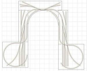
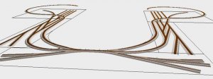
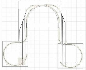
I am just throwing out these ideas as they come to me... Sounds like you have already thought of most of them... I agree that planning is very important, as well as the track laying. A friend of mine (Mike Hamer - see his layout by going to "Member Layouts" at www.ovar.ca) has much of his staging under a major city - almost completely inaccessible. He laid the track and then ran trains for months before covering it up to make sure that nothing could derail in an awkward spot. If he does get a derailment, he will have to rmove a good part of the city to get it. Now it is made to be removable, but not frequently!

In any case, I hope that my thoughts are still useful and might trigger some ideas on your part, but it sounds as if you've thought this through a million times...! :D

Andrew
 

Pitchwife

Dreamer
Apr 23, 2001
1,728
0
36
71
The middle of nowhere Oregon
Visit site
Andrew, Triplex, Jeff and everyone else who have made suggestions, I truely appreciate your input. :thumb: :thumb: You have all given me much to think about. I have taken a little from all of your suggestions and am in the process of redesigning the staging and think I might be on to something. I'll post it once I fine tune it a little.
Thanks again for all of your help. :wave: :thumb: :wave: :thumb:
 

Pitchwife

Dreamer
Apr 23, 2001
1,728
0
36
71
The middle of nowhere Oregon
Visit site
OK. Here is the latest version of my staging area based on all of your points and ideas. The one thing that I'm not sure of is on the left side where the mainline (red) goes through a series of turnouts. It runs through the "switched" section of all of them and they are all #4s. I have seen some layouts in MR where the mainline runs through turnouts like that, but not as many in a row. On paper it looks good, like a smooth curve, but I don't know what it will be like in reality. Am I just looking for trouble? I suppose that I could set up a series of them on a test track and see what happens.
The other area is on the right side where the sidings exceed the 1' limit, but they are straight and dead ends. So far it is the best utilization of space that I've come up with. Let me know what you think.

Layout%20help_4.jpg
 

tillsbury

Member
Jul 18, 2004
252
0
16
56
NZ
That does look a little like asking for trouble, to me. Especially coming out of a curve the other way on the helix. Any slight dodginess will lead to pain.

On the other hand, can you make it such that most trains will be going the other way (i.e. approaching the helix on the left). That way, that string of points won't be an issue. And you don't have the same issues on the other side. What's your normal direction of travel, again? If it's from the right-hand helix to the left-hand one then it looks good to me...

Charles
 

Pitchwife

Dreamer
Apr 23, 2001
1,728
0
36
71
The middle of nowhere Oregon
Visit site
I had planned on having two way traffic. If I wanted to just let something run around in one direction that would work. I plan on going with DCC eventually with the possability of having more than one train on that track. I suppose that if I wanted traffic to go in the other direction it could come out of the yard on the right, make a loop, and then enter the yard again from the other direction so it doesn't have to go through all of the turnouts. I'll keep kicking it around some more and see if I can't come up with something better.
 

TrainClown

Member
Apr 17, 2003
861
0
16
66
Saskatchewan, Canada
Visit site
Hi Clark, So I did some thinkin' on yer perdicament and came up with something different. Now the first thing I want you to notice is that I have rounded out the bench work. This gives the tracks more room, and shouldn't be a problem in practice, meaning, this shouldn't be a problem accessing the top tracks.

Now the track descends down the helix,and then keeps descending down to the double three way switches. I'll call this level, "level A". Now the tracks that come off the top of the tree way switches are level with the three way switches and level A. The center track of both three way switches descends again at 2% grade down to "level B" On level B is where your main switching yards are. This extra drop down to level B is what was needed to give your trains clearance on the track as it comes off the helix. I checked this by putting an engine on the track and running it under to check the clearance.


You probably won't use this plan, but perhaps it will give you an idea of how to gain more usable bench work out of what you have to work with.

TrainClown ;)

Pic 1................the plan

Pic 2................3D view of the plan

pic 3.................3D view of left side

pic 4..................This view shows the elevations of the track and how they drop.

pic 5..................This shows the clearance of the track above the engine. The cab is directly below the track.
 

Attachments

  • U shape N plan.jpg
    U shape N plan.jpg
    39.5 KB · Views: 42
  • U shape N pic 3.jpg
    U shape N pic 3.jpg
    27.4 KB · Views: 19
  • U shape N pic 4.jpg
    U shape N pic 4.jpg
    23.3 KB · Views: 19
  • U shape N pic 2.jpg
    U shape N pic 2.jpg
    19.1 KB · Views: 21
  • U shape N pic 1.jpg
    U shape N pic 1.jpg
    29.5 KB · Views: 21

kchronister

Member
Nov 1, 2004
353
0
16
54
Boiling Springs, PA
I think trainclown has hit upon your best possible solution, which is to manage the grades so that your staging can run under the helix.

I would, myself, de-complicate the actual suggestion for a staging environment, though. Get rid of what appear to be runaround, loco storage, etc. tracks in favor of maximizing long tracks in which to stage trains. I think you can easily get 4 long tracks going each direction as shown in my attached (rough) drawing. (Sorry, I don't have 3rd planit here to do this nicely).

Kris
 

Attachments

  • staging.jpg
    staging.jpg
    21.7 KB · Views: 20

kchronister

Member
Nov 1, 2004
353
0
16
54
Boiling Springs, PA
I forgot to mention, one other change I made. I would push the "top" curve as far back as possible - your limiting factor there seems to be the track leading to staging on the right which must clear the wall you've indicated... So I actually proposed two changes to what Trainclown suggested. Decomplicate the yard layout, and push the top up to maximize track length.
 

Pitchwife

Dreamer
Apr 23, 2001
1,728
0
36
71
The middle of nowhere Oregon
Visit site
TC, you never cease to amaze me! :eek: I had never thought of using two different levels in the staging area, but am going to look at it more seriously now. :thumb: :thumb: It won't be difficult because of the way I built my helix's. I originally had three loops, but when it was together I decided I could put another loop in, decreasing the grade while keeping sufficient clearance. I'm trying to put some pics together to show how it was done. I don't have a digital camera yet so it's taking a little longer.

kchronister, I like your simplified version and agree that long staging tracks are desireable. Kudos to both of you. :thumb: :thumb: :thumb: :thumb:

While reading through tillsbury's reply about going through multiple sets of points I got an idea of how to eliminate the points from the mainline by using a Peco Double Curve turnout. Since I'm using RTS there is no such critter in their library so I am having to manufacture one using flex track. When I get something put together I'll post it. I like the idea of a through yard. Not having to back up a long train would eliminate a lot of potential problems, but if it will increase the capacity then so be it.

Many thanks to all who have contributed. All of your comments have helped, and I'm sure that whatever I end up with will be better because of them. :thumb: :thumb: .......
 

TrainClown

Member
Apr 17, 2003
861
0
16
66
Saskatchewan, Canada
Visit site
Hi Clark. Well........after a good scratch, ai came up with this plan. I couldn't help put a run-around track up top. If yer gonna stage yer trains, you should have a way to line them up without havin' the giant pink crane swing into action. :rolleyes:

The rest is self explanatory. Run around at the bottom lets you drive the trains into the storage yard. But I couldn't help put the spur on the inside. I had to make use of that space too. Maybe this is where you would put the trains/cars on the track to enter the system.

TrainClown ;)
 

Attachments

  • U shape N plan A.jpg
    U shape N plan A.jpg
    41.7 KB · Views: 19
  • U shape N pic A.jpg
    U shape N pic A.jpg
    25.8 KB · Views: 19
  • U shape N pic B.jpg
    U shape N pic B.jpg
    21.4 KB · Views: 20

Pitchwife

Dreamer
Apr 23, 2001
1,728
0
36
71
The middle of nowhere Oregon
Visit site
That's a good plan TC. The only problems I see are the two turns at the bottom that I've marked in red. By my calculations I make their radius at about 11", a mighty tight corner, especially for longer trains. Also the area at the top can't be rounded out too much. While the staging level is only 1' deep, the top level is 27" deep and I still need to be able to get at a large part of that. I still like your dual layered staging idea. :thumb:
 

Attachments

  • U shape N plan A1.jpg
    U shape N plan A1.jpg
    39.1 KB · Views: 24

TrainClown

Member
Apr 17, 2003
861
0
16
66
Saskatchewan, Canada
Visit site
Hi Clark. You might want to run a test, because a 11 inch curve in N gauge would be a 22 inch curve in HO gauge and from what I understand, this isn't to sharp a curve for long trains. I could be wrong about this. What do you other N gaugers think? Is an 11 inch curve to tight for a long train in N gauge?:confused:

Always seeking perfection. :rolleyes:

TrainClown ;)
 

tillsbury

Member
Jul 18, 2004
252
0
16
56
NZ
11" is absolutely no problem reliability-wise in N. It looks daft when you have long (85') cars, and you need to make sure you don't have problems with overhangs touching things nearby, but neither of those is an issue here.

With very long trains (e.g. inside helices), you can improve resistance to stringlining by putting a negative superelevation on the track. Coo there were a lot of long words there for a Thursday... :)

Charles
 

Pitchwife

Dreamer
Apr 23, 2001
1,728
0
36
71
The middle of nowhere Oregon
Visit site
I came here to the Gurus for advice and I'm going to take it. TC, I think your plan is great and tillsbury says that 11" curves will work with no problems and that's good enough for me. This is much better than anything that I'd have come up on my own. I will probably move the top end up a little, maybe flatten out the "Grin" to make sure that I can get at the top level easily, but otherwise I see no reason to change anything else. I'll try to get some pictures to post to keep you up on my progress. Thanks much guys. :thumb: :thumb: :thumb: :thumb:
 

Pitchwife

Dreamer
Apr 23, 2001
1,728
0
36
71
The middle of nowhere Oregon
Visit site
I thought that 11" did sound tight, but Atlas offers a snap track at 9 3/4". I plan on testing, or fiddling with it to see if I can't stretch it out another inch or so, or even counter-hyperelevating it, but as long as it handles the rolling stock it's fine. The longest cars that is will be required to handle will be 85' passenger cars. No 2-8-8-0 Bigboys on this line, at least this time around. Also it will be hidden so aesthetics isn't important, preformance is all that matters.
 

TrainClown

Member
Apr 17, 2003
861
0
16
66
Saskatchewan, Canada
Visit site
Ok Clark, here are the specs.

It's called a MC Three-way

Angle is 24.3

Frog mumber is 2.322

normal length = 7 13/32"
Routing Length = 7 1/4"
Entry to intersection = 4 11/32"
Rail closure radius = 11 13/16"
Centerline to routing exit = 1 21/32"

If it was me, I would go to the LHS and see what they have, and then work with that. I'm sure there is room for artistic interpretation.

All the other switches are Atlas No. 4

TrainClown ;)
 

Pitchwife

Dreamer
Apr 23, 2001
1,728
0
36
71
The middle of nowhere Oregon
Visit site
Thanks TC. I've been converting your design into RTS to see how it's going to fit in with the rest of my plans. I came up with a way to increase the radius of the lower loops, not much but every little bit helps. :thumb: RTS doesn't have anything like the 3way so what I did was overlap 4 #6s. :rolleyes: Not everything is directly connected but will be in the long run. I figured out pretty soon that the other switches were #4s. It's been a chalenge to duplicate your design but I think it'll be worthwhile. On the right hand Y at the top, the tail only came out to about 7". I know you had it lower with longer tails, but I think it's enough to handle a single engine. I might even leave that part off just to simplify the layout. So far so good. Will keep updating the progress. :wave: