

It is cool when these old threads resurface. Hope it can be of interest and a help to somebody. As of now, my layout is nowhere near in running order yet, but I have used the bridge on several occasions and so far it works great. I still need to build the buttresses that it will rest on, I will devise an adjustable mounting means so I can keep the tracks in alignment, allowing for minor changes in the layout due to environmental conditions.
My Bridge Project
- Thread starter Gary S.
- Start date
You are using an out of date browser. It may not display this or other websites correctly.
You should upgrade or use an alternative browser.
You should upgrade or use an alternative browser.
it looks great!! I do have one question. Call me a rivet counter but wouldn't a bridge like that have supports under each side of the truss section?
Maybe you could affix a couple blocks of wood to the bridge painted like cement piers
Maybe you could affix a couple blocks of wood to the bridge painted like cement piers
VERY NICE ,the only problem is...you left no room for criticism let alone "constructive" criticism.LOL
b28_82 said:wouldn't a bridge like that have supports under each side of the truss section?
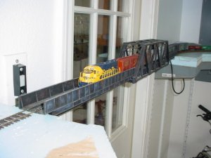
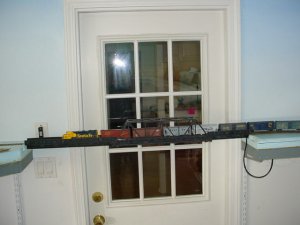
You're absolutely correct. But I need to explain what this bridge does. It spans across a 3 foot doorway, and is completely removable. It will only be on the layout when the layout is in use, otherwise it will be stored under the layout shelving. so, I'm not shooting for total realism in this spot, just a way to get the trains across the doorway.
I had considered building the river and the supports and all that under the bridge, and maybe someday I will, but for now I will just keep it simple and easy to install/remove.
If I do put some scenery underneath, I would attach some 1/4 plywood to form the terrain underneath, install the supports, and then do a river and the river banks.
Great looking bridge...!!!
I just finished setting up a truss bridge on my layout
http://www.the-gauge.com/showthread.php?t=26281
and had lightly weathered it, but once installed it's very hard to actually see the weathering. I had thought to dry paint some additional weathering. I see that this is a good solution. Your bridge looks awesome...!!!:thumb:
A good idea for your bridge, Gary. :thumb: I used a simple 3/4" plywood lift-out section at the layout room doorway, then mounted a 5-pin female plug on the layout facia on one side of the opening. The male connection is on a short wire hanging from that end of the lift-out, while power for the layout on the other side of the gap is provided by wires running above the suspended ceiling.
Wayne
Wayne
I realised that this thread is almost a year old, but somehow I never saw it before. That bridge is fantastic and an awesome way to make lift out for an entry into the layout. As I was reading through, I saw a method to handle the electrical connections that I think is so simple that I have to share it in case someone else is going to make something similar.
You would need two electrical junction boxes for household plugs, two 2 outlet recepticles, four plugs to fit the recepticles, and some 18/2 lamp zip cord. Use grounded type plugs and recepticles so that the ground pins become alignment pins & polarity protectors.
First thing you do is cut gaps in all four rails about 3 feet back from each end ofthe door, and insulatre the rails. Now with the bridge removed there is no power on the last three feet of the tracks leading to the bridge on either side. Put a 110 volt type 3 prong male plug on the end of each track to the side of the bridge wired to the tracks on the positive and negative poles of the plug. The ground pin is left unconnected to act as an alignment guide and polarity protector. The other 2 male plugs are installed at each end of the bridge also wired to the rails. Make the distance between the plugs when the bridge is installed such that a standard two receptile gang will connect both plugs at the end of the bridge with the plugs at the end of track leading to the bridge. Install the recepticles into the two junction boxes, and run enough zip cord to the recepticles to make a connection to the buss wires beyond the gaps. The plugs are wired to the two rails on the bridge and the two insulated rails on each side of the bridge. When the bridge is set in place, the two junction boxes plug into the plugs at each end and feed power from the main buss to the rails from gap across the bridge to the other gap, and lock and align the bridge with the tracks on either side. To remove the bridge, pull the two junction boxes off the plugs, and remove the bridge.
Russ that's quite a good idea- that way your layout can be either a point to point for when you operate or continuous when you just want to sit back with a cold one and admire that new loco, train or just what you've done on the layout.
BRAVO!! This looks (and obviously works) FANTASTIC!!! I was waiting a long time to actually see it work! Lookin' SWEET! :thumb:
 :thumb: :thumb:
Great job of engineering a solution to a problem that comes up quite frequently here on The Gauge. That is, how to get past that darn door with the layout. Nice job.
Hey Russ:
I sort of used your idea for powering the bridge. I have an appliance cord connected to the bridge wiring, and I installed a receptacle under the layout, so when the bridge is in place, I just plug it in. Now, I really need to do something to take power off the track by the bridge when the bridge is not in place. Otherwise, the inevitable will happen, and a loco will "take the big drop" with very little chance of survival.
I sort of used your idea for powering the bridge. I have an appliance cord connected to the bridge wiring, and I installed a receptacle under the layout, so when the bridge is in place, I just plug it in. Now, I really need to do something to take power off the track by the bridge when the bridge is not in place. Otherwise, the inevitable will happen, and a loco will "take the big drop" with very little chance of survival.
Gary, if you gap a length of track on either side of the bridge, then pick-up power for the plug from back of that, you can use the plug to power both the bridge and the approach track. I used a 5-conductor plug from Radio Shack to do this on a previous layout: two of the prongs connected to the power source, with the wire feeding power to the bridge, then another pair of wires fed that power back, through another pair of prongs, to power the approach rails. I ran another pair of wires from there, over the doorway, to feed the approach tack on the opposite side. When the plug is disengaged, the bridge and both approach tracks, back to the gaps, are dead. The 5th prong on the plug ensured that things could only be connected one way.
Wayne
Wayne