"The Great Undertaking" -- GPM's Leopold Rail Gun

sakrison

Banned
"The Great Undertaking" -- GPM's Leopold Rail Gun -- Post #1

Ten days ago, I displayed some paper models at an IPMS meet in Milwaukee, Wisconsin (see my "Milwaukee IPMS Contest Report" under "NEWS.") One of the things that attracted the most attention was an unbuilt copy of GPM's "Leopold" Rail Gun in 1/25 scale. All that attention inspired me to build that kit for next year's IPMS meet. This is the first report on the project. I'll add more posts as the Great Undertaking progresses.

I've never built a paper model this large. But looking at the kit, it appears that it will require no skills or techniques I haven't already used on smaller (saner) models. So here goes.

I've started with one of the two rail cars--specially-built flat cars--that carry the cannon. The first step is to assemble the leaf springs. Choose your card thickness carefully here and do some test fitting and experimenting. Part 1c is the vertical band that fits over each spring. It should reach just to the bottom of the leaf spring. If it doesn't, your springs are too thick. I'm not sure what thickness card I used and I don't have a way to accurately measure it, so you'll have to work it out by experimenting.

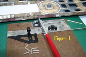
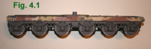
The two side frames (Fig 1) go together fairly easily. You'll need extra-heavy card for the side frames and brake frames, and for the car body when you get that far. Picture framing matte board seems to be about right--somewhere around 1.5 mm or a little less than a 1/16" thick. (See below: A Note about Heavy Card.") The first side frame took me about a week of evenings. The second is going a bit faster. They're big; that's a six-inch ruler. I made a few modifications:

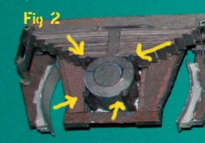
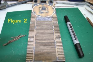
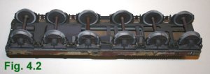
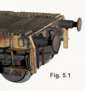
Four bolts secure each of the wheel bearing cases. The ones supplied in the kit (parts 1k) are too short. They should be as tall as the side of the bearing case. Scan a strip of 12 parts 1k, enlarge them to 190%, and print them on good quality inkjet paper or matte photo paper (20-24 lb). Then roll them and attach them according to the instructions. (Fig 2)

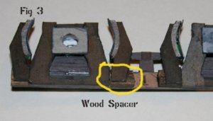
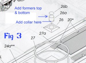
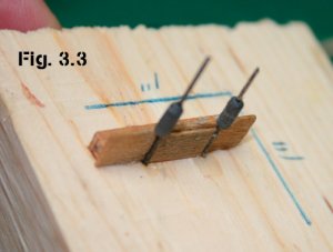
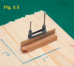
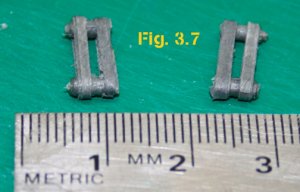
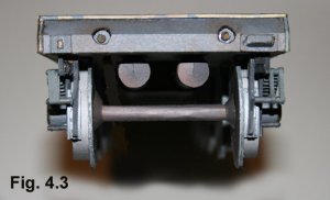
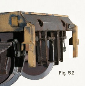
The kit instructions show the brake brackets (parts 2aP & 2aL) attaching directly to the back of the side frame. But if you mount them that way, they won't line up with the wheel treads--they'll be too far outboard. I made spacer blocks from 1/8-inch thick basswood. (Fig 3) Then I built up one wheel and axle and used that as a guide to position the brake brackets.

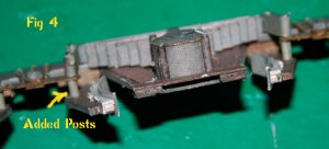
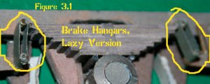
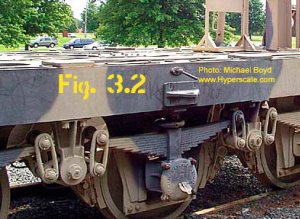
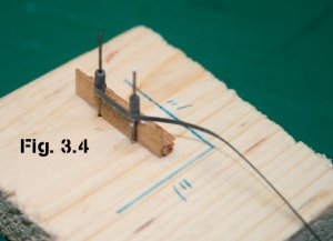
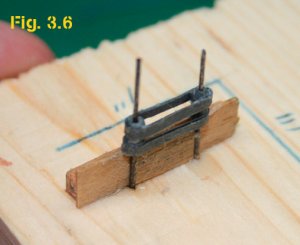
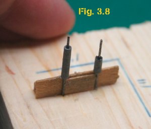
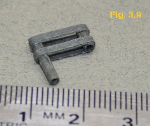
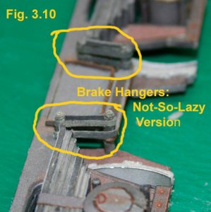
With the brakes positioned farther inboard, you'll have to add extra posts to the brake pivots (see Fig 4). I don't have any good photos, drawings, or models of a 1940s European rail bogie, but this looks about right and it makes sense. If you have better information on what this prototype assembly SHOULD look like, please post it here.

Once I've finished the other sideframe, I'll move on to building the flatcar.
I expect (I hope) my model photo skills will improve as well.
Stay tuned.

No worries,
--David

A Note about Heavy Card:
The ideal card stock for the laminated parts marked "**" seems to be about 1.3-1.5 mm thick. I built the first rail car with a sheet of heavy (about 1.4 mm) card I bought from Lighthouse Model Art. I think Ralf got it from Fly Model. (Lighthouse is, sad to say, no longer in busiess. We miss you, Ralf.) For the underframe on the second rail car, I used picture matte board and found it just a hair thicker but much more dense and much harder to work with. For the rest of the kit, I'll snitch heavy card from some of my unbuilt Fly Model kits. For those kits, I can substitute scrap and scrounged material (for fuselage formers and wing spars). Live and learn.
 

Attachments

  • Leopold Fig1.jpg
    Leopold Fig1.jpg
    44.1 KB · Views: 693
  • Leopold Fig 2.jpg
    Leopold Fig 2.jpg
    40.3 KB · Views: 1,101
  • Leopold Fig 3.jpg
    Leopold Fig 3.jpg
    50 KB · Views: 374
  • Leopold Fig 4.jpg
    Leopold Fig 4.jpg
    53.4 KB · Views: 494
C

cgutzmer

David - looking good from what you have done already! Excellent attention to detail. Looking forward to more!
Chris
 

sakrison

Banned
Post #2: Working on the deck

This is the flatcar that carries the rear of the gun carriage. Assembly of the car body is very straightforward. I used a leather punch to cut and "nibble" out the curved openings. I sanded the openings a little but, with the weathering around the openings, you don't have to be exact.
I colored the inside surfaces with a dark blue-gray artist's marker--too blue for my taste but it's what I had on hand and it will just look dark once the model is completed.

I had to add an extra layer of heavy card between the inner (parts 5a) and outer (parts 15) side frames, to match the width of the top deck (part 24a), and I trimmed the end block (part 5i) a little to get the side frame to fit flush with the deck. Other than that, the car body main assembly went together very well.

Parts 5d and 5h--end frames--look interchangeable, but they aren't. Study the drawings carefully to make sure you're putting the right one where it belongs.

There is some wood decking on each railcar. The kit provides paper parts--a LOT of paper parts--for the wood. I do a lot of scratchbuilding for my model railroad and I've always believed that nothing else looks as much like wood, as wood. I used HO-scale dimensional lumber for the decking--6"x8" for the short blocks on each side (parts 25), and 2"x8" for the planking in the middle (part 24b). I applied the planking directly to the deck after coloring the white area under the planking with a gray watercolor marker, in case there were any gaps between the planks.

I stained the wood using a "weathering goop" of shoe dye mixed with rubbing alcohol. (I'm not sure of the ratio--I mix it myself in several different strengths.) Wood stain and alcohol works, too. I cut the wood on a Northwest Shortline "Chopper," (Fig 1) stained the cut ends, and glued the blocks and planking down with tacky glue. You can see the results in Fig 2.

The round post in the middle of the flat car (parts 26a and 26b) has no reinforcement--it's just a tube with a paper cap (Fig 3). It could get some abuse if I haul the model around to shows, so I laminated the top cap to 1mm card and made a 1mm former for the bottom of the tube. There is a printed ring around the bottom end of the tube that lines up with the edge of the base (part 26). I used a strip of scrap to create a collar around the base of the tube to support the top of part 26, glued the tube into the base, then glued the whole assembly down. The whole assembly is much sturdier this way.

So far, I have about 3 weeks of evenings invested in this project and I'm very pleased with the kit and the results. Wheels are next. Stay tuned.

No worries,
--David
 

Attachments

  • Leopold-2- 032-small.jpg
    Leopold-2- 032-small.jpg
    102.3 KB · Views: 313
  • Leopold-2- 033-small.psd.jpg
    Leopold-2- 033-small.psd.jpg
    97.2 KB · Views: 308
  • part 26001.jpg
    part 26001.jpg
    136.6 KB · Views: 305
J

Jim Nunn

David,


I’ll be keeping an eye on this build this is a challenging model both in size and detail.

I have this model and found that the kit was missing some parts as I remember they were the very first parts something like 1d. If you are missing the parts drop GPM a note it will take a while but they did send me the missing parts in a cdr file. I would send them to you but I lost them when my last hard drive crashed.

Jim Nunn
 

Gearz

Member
Very Interesting build David, looking forward to its progress..

Odd... I would have thought an Arty weapon of that calibre, would have had a greater range than 20,000 m. ?? Even the old M2A2's (105 mm) had 11,000 ...
:confused:
 

charliec

Active Member
Gearz said:
Very Interesting build David, looking forward to its progress..

Odd... I would have thought an Arty weapon of that calibre, would have had a greater range than 20,000 m. ?? Even the old M2A2's (105 mm) had 11,000 ...
:confused:

That doesn't sound right - Wikipedia says 61,000 m and the site
http://www.e94114.de/Eisenbahngeschuetze/K5_Leopold.htm#Daten says 62,200 m. The barrel was 76 calibres long with a muzzle velocity of around 1100 m/s - the longer range sounds plausible. I think you've got to be careful about comparing modern with older artillery - the much longer ranges of modern artillery are mostly due to better shaped projectiles (after the work of Gerald Bull) rather than major improvements in the gun itself.

Regards,

Charlie
 

sakrison

Banned
The Leopold's Range

Here's what the US Army Ordinance Museum says:

"Called 'Anzio Annie" by Allied forces during the Italian Campaign of WW II. This railroad gun evolved from the large siege guns of WW I. It can accurately fire about 31 miles. A rail crew would curve the track to provide a wide angle of fire. Twenty-five of the K5 280 mm series were made. This gun was captured in Italy after it and a second gun ('Robert') had been firing on the Anzio beach head. The guns were hidden in mountain tunnels when not firing."

That 31 miles of accurate range equals about 50,000 yards. Absolute range (With a shell that size, what does a little inaccuracy matter between friends?) might be 20% farther or more.

No worries,
--David
 

Gearz

Member
Of course.. Point taken gentlemen.. Those ranges sound a lot more credible, I'll have to put it down to comment without thought, and lazy reading. The blurb on the strategyplanet page (linked above) quotes

The Leopold had an unconfirmed range of 11 miles and fired a pre-engraved projectile....

Typo ?

Projectile shape yes.. I'd imagine improvements in propellants would have to be considered as well = No more old<>new comparisons for me!!

Now.. I'll just slip quietly to the back of the hall, and enjoy the rest of the build -

8)
 

sakrison

Banned
Post #3: Brake Hangers Revisited

When I first looked at the brake hangers (Parts 1, 1a, & 1b), I didn’t especially like what I saw: a bunch of tiny parts that would require a lot of very fussy labor. So I cut a corner. I used the posts (Part 1), tossed the caps (Part 1a), and made my own straps (replacing Part 1b). See Figure 3.1. As I noted in an earlier entry, I didn’t know what these looked like on the prototype, and they looked about right to me on the workbench.

Then CharlieC’s post to this thread led me to some very good prototype photos (Fig. 3.2), and I knew I had to do better. I still didn’t like the kit parts. I found some dark brownish-gray paper in my daughters' craft cabinet, and tinted it with a watercolor marker to get a close match with the kit parts. Then I built a jig using a small pine block for a base, two pieces of piano wire (superglued into the wood), and basswood scrap for spacers. (Fig 3.3). I cut long strips of my tinted paper the same width as the height of the posts, and used my NWSL “Chopper” to cut them to length (after experimenting to determine the right length). Then I rolled the posts on another piece of wire and slid them onto the wires on the jig.

I cut another long strip for the bands and glued one end to the base of one post, (Fig. 3.4), then wrapped it twice around both posts, gluing as I went (Fig. 3.5) and trimming to length on the jig.

[Continued on the next post]
 

Attachments

  • Review 3-1.jpg
    Review 3-1.jpg
    84.5 KB · Views: 208
  • Review 3-2.jpg
    Review 3-2.jpg
    88.3 KB · Views: 899
  • Review 3-3.jpg
    Review 3-3.jpg
    53.9 KB · Views: 180
  • Review 3-4.JPG
    Review 3-4.JPG
    52.5 KB · Views: 181
  • Review 3-5.jpg
    Review 3-5.jpg
    62.5 KB · Views: 227

sakrison

Banned
Construction Post #3 - Continued

I attached the second band the same way (Fig. 3.6), gave the glue a few minutes to set up, and carefully slid the assembly off the jig (Fig. 3.7). Once I got the hang of it, the process of building a dozen of these little rascals went pretty quickly.

The posts look like they have nuts on their ends. That's a happy accident that comes from the fact that my fingers are too fat to roll these small parts perfectly straight. Clumsiness can sometimes pass for talent when everything turns out right.

Earlier, (see Post #1) I recessed the brake shoes, so they would line up with the tires. As a result, each of the two brake hangers at each end of the side frame needs one longer post. The prototype photos don’t show this detail, so it’s a SWAG* on my part, but it will probably be hidden behind other sideframe details, anyway. So it goes.

I measured to find the length of the long post, cut strips from the tinted paper, and rolled the posts. I used the same jig (Fig.3.8 ) and assembled the hangers the same way (Fig 3.9). You can see the results in Fig 3.10.

When I build the car at the other end of the gun, I’ll probably make the brake hangar straps about half as wide as I did here. On the prototype, they look more, well, “delicate” isn’t the right word, but you can see for yourself.

What about the Lazy Version of the brake hangers on the first sideframe I built (Fig. 3.1)? I haven’t replaced them—yet. For now, they are on what will be, from most viewers' perspective, the back side of the model. If they seem too conspicuous later on, I’ll replace them.

No worries,
--David

*"Scientific Wild-Assed Guess"
 

Attachments

  • Review 3-6.jpg
    Review 3-6.jpg
    58.7 KB · Views: 143
  • review 3-7.JPG
    review 3-7.JPG
    63.7 KB · Views: 161
  • review 3-8.JPG
    review 3-8.JPG
    54.8 KB · Views: 116
  • Review 3-9.JPG
    Review 3-9.JPG
    71 KB · Views: 135
  • Review 3-10.JPG
    Review 3-10.JPG
    97.5 KB · Views: 157
C

cgutzmer

That is awesome detail! I am really enjoying watching how you are doing things. I really appreciate the picture of the way you set up that jig!
Thanks!
Chris
 

sakrison

Banned
Construction Post #4: Wheels

There are twelve wheels and each one has 3 disks. I got dizzy cutting them all out. (Put the wheel on the jig, grab the curved scissors, and walk around the jig, cutting as you go.)

Right.

I cut out and assembled the wheels, rolled the axles, and stuck the former loosely onto the latter.

I glued one sideframe (a) to the body and left that overnight to cure. The wood spacer blocks for the brake shoes were mounted level with the tops of the sideframes and really helped square everything up here.

The next evening I stuck the axles/wheels into sideframe a, stuck the other ends into sideframe b, and carefully glued down the second side frame. I gave that about an hour to cure, then slid each wheel into position and glued it to its axle and to the back of its bearing case.

A purist might say, "But the wheels can't roll." Well, I don't really want this monster rolling away from me, and gluing the wheels, axles, and sideframes together makes for a much sturdier assembly all around.

Each axle has a tapered collar (part 5a) that fits against the back of each wheel. I installed these collars only on the axles on each end of the car, where they can be seen. I see no point in spending time adding details that no one will ever see. You'd need a mirror, a flashlight, and an attitude to see those inside axles and their missing parts.

You can see the results in the photos. It's big--about 375 mm long. (That's a couple hairs short of 15 inches.) Fig. 4.3 is of the inside end of the car (no coupler). The two round things above the axle are the ends of two air tanks. Note the different brake hangars and the correct alignment of the brake shoes on the right side. I think I'm going to have to replace those Lazy Version Brake Hangers after all--eventually.
 

Attachments

  • Leopold 4-1.jpg
    Leopold 4-1.jpg
    40.7 KB · Views: 223
  • Leopold 4.2.jpg
    Leopold 4.2.jpg
    46.8 KB · Views: 152
  • Leopold 4-3.jpg
    Leopold 4-3.jpg
    55.5 KB · Views: 168

rlwhitt

Active Member
VERY cool project, David!

How large were all those disks? I just got a hobbico circle cutter and it does a pretty decent job, all the way down to 2 cm diameter. And it only cost about $8-9. Too late for this project, but it sounds like it'd be a big help with something like this.

Lookin' good!
Rick
 

sakrison

Banned
Looking for a German Soldier in 1/25 (75-80mm) scale

To provide scale for the finished model, I want to put a single German soldier (a sentry) on the Leopold when it's finished. Does anyone know where I can find a metal or preferably plastic figure in 1/25 scale or 75-80mm size?

I know Tamiya makes a few metal figures and one of them (see photo) would work with some modification. I'm looking for other possibilities, especially in plastic or resin.

Thanks,
--David
 

Attachments

  • Tamiya1.jpg
    Tamiya1.jpg
    21 KB · Views: 1,025

sakrison

Banned
Circle Cutter

rlwhitt said:
VERY cool project, David!

How large were all those disks? I just got a hobbico circle cutter and it does a pretty decent job, all the way down to 2 cm diameter. And it only cost about $8-9. Too late for this project, but it sounds like it'd be a big help with something like this.

Lookin' good!
Rick

I have an Olfa Circle cutter that would do the trick, but I haven't used it much at all before this, and I need more practice with it. I have two issues: For wheels and other disks for which the center is not marked, I need to figure out some way of accurately finding the center. And on thick card (0.5 mm or more), the best method seems to be to use circle cutter to make a shallow starting cut, which then guides my scissors.

If anyone has tips for using the circle cutters, I'm all ears.

No worries,
--David
 

charliec

Active Member
Look in the Parts Bin - there are a couple of circle centre finders - print them on transparency. If you are cutting lots of disks all the same size - another way is to cut out a disk of plain card as a pattern with same diameter with your circle cutter - overlay the disk on the circle to be cut and use a needle to prick the center position. You'll probably get advice on using geometry to find the circle centres - that's o.k. for a few circles - not really feasible for a whole page of circles.

You're right about making multiple passes with the circle cutter - if you try to force it you'll find it will go out of adjustment and not cut the desired diameter.

Regards,

Charlie
 

sakrison

Banned
#5 Car End Details

A couple of evenings finished off the car ends. This is where I learned about unintended consequences.

The wood spacer blocks and repositioned brake frames (see Post #1) interfere with the framework that hangs down below the end beam of the car. I solved that by leaving off the outer parts of that assembly (7P/L & 7G). No one will miss the detail.

The frames on both ends use heavy piano wire for horizontal braces. I painted those after assembly with Model Master "Burnt Umber," which looks like a slightly rustier version of the kit's underframe color. There might be a better match, but this was what I had on hand and it looks good.

The other unintended consequence has more to do with my impatience. As I described earlier, I mounted one side-frame assembly to the car body and let that assembly aside to cure overnight. The next evening, I mounted the wheels, axles, and second side-frame, let them cure a half hour or so, and then spent a lot of time handling the car as I photographed it. One result is that the second frame is canted inward just a bit on the coupler end of the car. It's not obvious but it's annoying and it was avoidable. I'll fix it later; I've got a deadline to meet--an IPMS meeting this week.

Back to the endframe details: I added internal formers (disks) to the buffers (those piston-like things on the corners of the car--parts 14-14f) to make them stronger. I cut the side steps about a 3/8" narrower to stagger them a bit and to ensure that the bottom step would clear the brake hangers. I put the steps and frames together, mounted the assembly onto the sideframes, and painted the step hangers liberally with brush-on super glue. The glue I'm using dries flat and makes the steps strong and rigid.

Next up is the gun loading platform that fits onto this car.

No worries,
--David
 

Attachments

  • Leopold-5-1.jpg
    Leopold-5-1.jpg
    73.3 KB · Views: 143
  • Leopold-5-2.jpg
    Leopold-5-2.jpg
    74.6 KB · Views: 158
Top