NASA Voyager 1/48 John Jogerst
- Thread starter Tesco4
- Start date
You are using an out of date browser. It may not display this or other websites correctly.
You should upgrade or use an alternative browser.
You should upgrade or use an alternative browser.
Nooooooooooo!I feel your pain!
When I built the under-construction ring of UHU02s 2001 ASO Station V, (twice!), it was literally; Blood, Sweat & Tears!
Your truss turned out great!
Next up for both of us....UHU02s Tokyo Tower!!
https://www.zealot.com/threads/uhu02-tokyo-tower.179143/
...
...
...
Well ... maybe one day!
I had been eyeing up the 2001 space station as well over the last few weeks but have decided my skills aren't there yet, but again, perhaps one day. It does look amazing!
Thank you! Thinking of having a go at one of your TIE variations next maybe, but must stay disciplined and finish this first before making a final decision on what's nextThis looks amazing great work.
Yes, a nice discovery. It does stick to parts eventually if you leave them on it for long, but if the glue on the greaseproof paper is wet, it's fairly forgiving for a while.Great work, and the idea of grease proof paper to spread the CA on is a keeper! Hope the Vallejo Matt Varnish works good for you.
And yes, the Vallejo Matt Varnish works great, thanks
Last edited:
Need to keep the thread up to date with progress ...
RTG Truss:
I'm back trying to solve/interpret the instructions for the RTG truss. I'm going to show a fair bit of detail and explanation in case anyone else is building this model. However, I must say that although I think I've found a solution that works, it might still be wrong! I would love to hear from anyone who has built this before to find out what their experience of this aspect was like.
Here's the part of the printed sheet for reference. The one on the right is the large (inner) mounting truss and is glued to the side of the bus/main unit. The one on the left is the smaller outer mounting truss and connects to the RTG. I've shown which is which with the blue arrows.
Also note where it says the bottom of each one is. Each part is basically folded together, so "bottom" helps to know which half of each is facing up and which half is facing down.
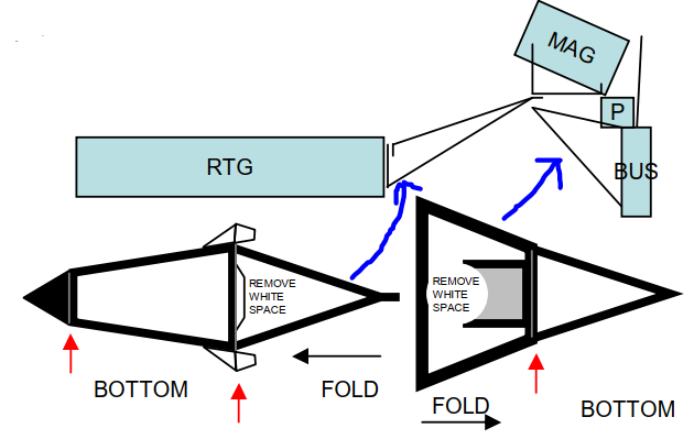
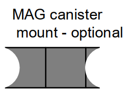
The difficulty arise in working out how to glue to two of these together once they're folded. The upper diagram is a side-on view of how these bits go together. It's a bit ambiguous because the large truss also includes that inner folding up half-circle piece which on the photos in the instructions shows the MAG sitting on that. But you'll discover that there's an optional MAG canister mount which is shown in the diagram. The side view also shows you what angle you should be aiming for when gluing the trusses together, so that the RTG ends up horizontal.
After having failed in my first attempt, I printed up a double size version to experiment with. It's much easier being this large. On the left is the smaller/outer truss (it's actually upside down), on the right is the larger/inner one. I coloured the underside of the outer one red to make it easier to see when they're joined together, which bits are connected.
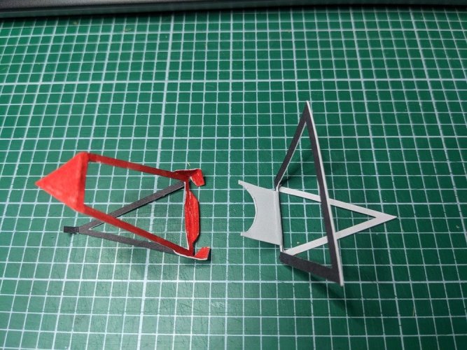
The photo below shows the two pieces folded roughly into their final angles-ish. The outer one on the left has been turned over from the photo above, so it's now the right way up. Also I glued the triangle together which you wouldn't do until you glue the RTG onto it, but I had to do it to make it stay folded at that angle for this illustration.
The small bent up flap on the left piece is going underneath the MAG canister mount on the right one.
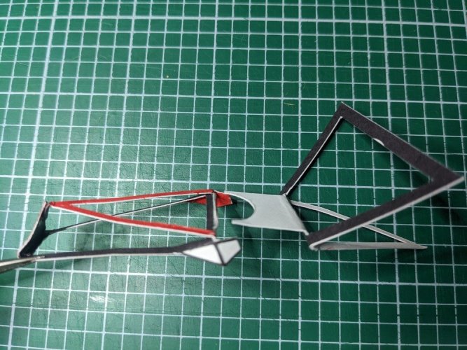
Here it is after gluing the two together. My confusion lay in the instructions where it says "Glue the centre tab over the fold on the inner truss". This is consistent with the diagram at the top of this post, where you can see the tab on the left hand side of the outer truss horizontal and overlapping the left hand edge of the inner truss, with the optional MAG mount on top of that.
In mine below, you can see that the MAG mount blocks you from gluing the tab over the fold. It's in the way. So I glued the tab underneath the MAG mount instead. If that MAG canister mount wasn't there, you could fold it over the top instead. When I've done it all properly and been able to work out how the optional MAG canister mount goes, it may be clearer. Perhaps the instructions were for if you've removed the MAG mount in preparation for using the optional one, but in all the photos in the instructions pdf (and the diagram at the top of this post), this MAG mount is still there and the optional one isn't used. Perhaps it was an improvement made after finishing the design.
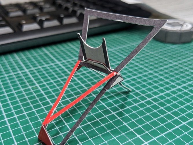
Anyway, onwards! Here's the other side to show those flaps at the sides being folded inside the lower arms of the inner truss - the angle of the flaps will help the assembly sit at the right angle.
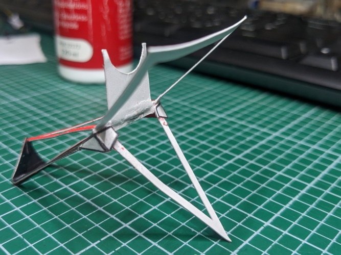
So onto having a go for real, at the smaller scale of the actual model ... Here are the two pieces folded, coloured black and cut. Here's the larger/inner truss in detail. The needle points to the tab surface that will be glued (the "hairy" bits will be cleaned off before being glued. It's amazing how many flaws a phone camera picks up that you almost can't see with the naked eye!)
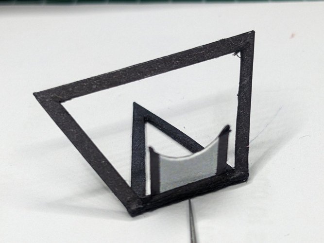
And the smaller/outer one.
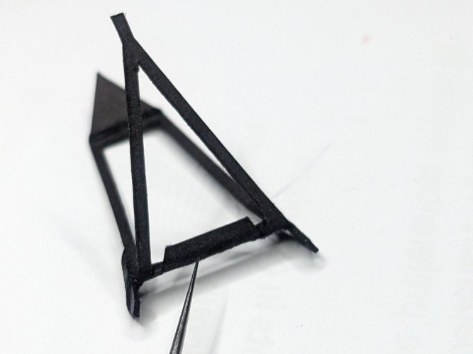
Before going any further, I put superglue on the 8 legs (4 on each truss) to strengthen them, being careful not to encroach anywhere where there will be folding to do. After finishing the gluing of this assembly I will coat the other side and anywhere I can reach, and then paint matt varnish over the lot for maximum rigidity.
First the inner truss is secured to the main bus at 3 points.
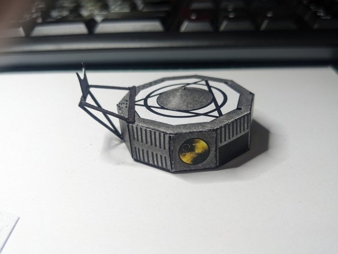
The angle is close enough to the side on illustration.

When gluing the two trusses together, the diagram can be used to help get the angle of the outer one right. The aim is that when the far ends of that (the big triangle to the little tab), the surface will be vertical so when the RTG is glued to it, the RTG sits horizontally. There's a bit of flexibility here because you can alter the final angle depending on how much of the upper tab you fold and glue to the big triangle folded up from the lower side.

As worked out with the double size version previously, the outer truss centre tab is glued to the mid-frame cross piece on the outside underside of the MAG cannister mount. After the tab is glued, then fold the side tabs down and round the inner truss lower legs to form the angle and glued them into place. This locks in the final angle of the two trusses together somewhat.
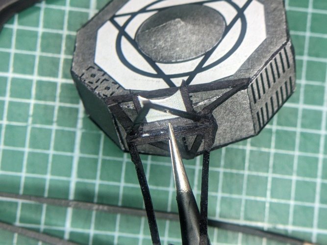
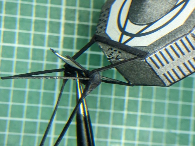
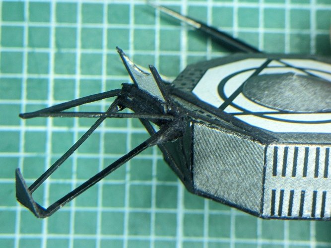
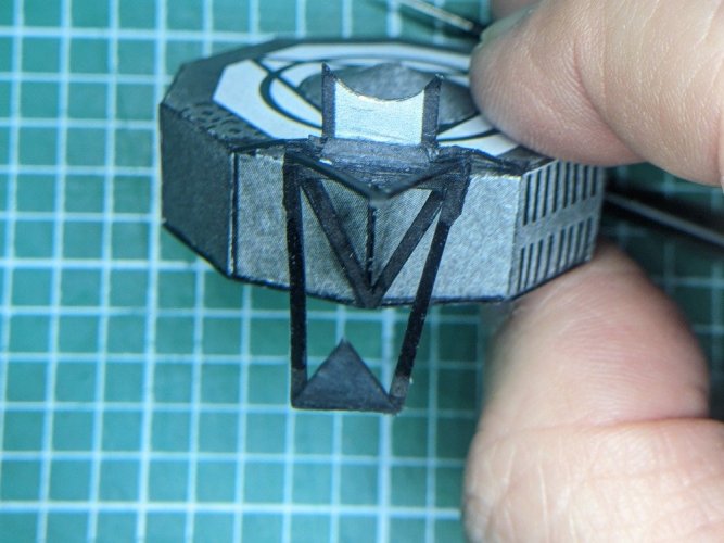
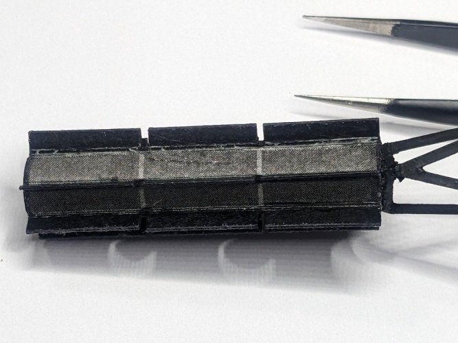
Both trusses in place. I glued the RTG to the triangle first, and then glued the triangle and upper tab together. It seemed easier to get the final angle correct looking at the RTG and what angle it's sitting at, rather trying to get the small vertical surface of the triangle on the end of the truss. The weight of the RTG caused a bit of sag on the whole truss, so best to take that weight into account before gluing it all up together. I got the angle a bit wrong and my triangle piece delaminated, so I just filled it in with PVA glue in the right position until I built it up to the surface. That's why the triangle section looks a little thick and wedge-shaped side on. Did the job though.
Once all the pieces were together I coated the remainder of the truss parts, including all the angles with EM-02 superglue which absorbs into the card really well, forming a strong and sturdy structure. Applied a coat of Flat Black paint (still trying on one of the struts) and if needed, a coat of the Matt Varnish to fully remove the CA glue's shine.
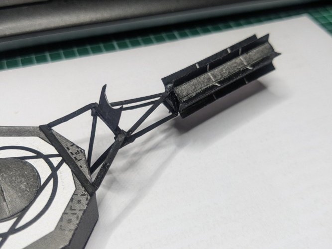
Phew, another section completed
RTG Truss:
I'm back trying to solve/interpret the instructions for the RTG truss. I'm going to show a fair bit of detail and explanation in case anyone else is building this model. However, I must say that although I think I've found a solution that works, it might still be wrong! I would love to hear from anyone who has built this before to find out what their experience of this aspect was like.
Here's the part of the printed sheet for reference. The one on the right is the large (inner) mounting truss and is glued to the side of the bus/main unit. The one on the left is the smaller outer mounting truss and connects to the RTG. I've shown which is which with the blue arrows.
Also note where it says the bottom of each one is. Each part is basically folded together, so "bottom" helps to know which half of each is facing up and which half is facing down.

The difficulty arise in working out how to glue to two of these together once they're folded. The upper diagram is a side-on view of how these bits go together. It's a bit ambiguous because the large truss also includes that inner folding up half-circle piece which on the photos in the instructions shows the MAG sitting on that. But you'll discover that there's an optional MAG canister mount which is shown in the diagram. The side view also shows you what angle you should be aiming for when gluing the trusses together, so that the RTG ends up horizontal.

After having failed in my first attempt, I printed up a double size version to experiment with. It's much easier being this large. On the left is the smaller/outer truss (it's actually upside down), on the right is the larger/inner one. I coloured the underside of the outer one red to make it easier to see when they're joined together, which bits are connected.

The photo below shows the two pieces folded roughly into their final angles-ish. The outer one on the left has been turned over from the photo above, so it's now the right way up. Also I glued the triangle together which you wouldn't do until you glue the RTG onto it, but I had to do it to make it stay folded at that angle for this illustration.
The small bent up flap on the left piece is going underneath the MAG canister mount on the right one.

Here it is after gluing the two together. My confusion lay in the instructions where it says "Glue the centre tab over the fold on the inner truss". This is consistent with the diagram at the top of this post, where you can see the tab on the left hand side of the outer truss horizontal and overlapping the left hand edge of the inner truss, with the optional MAG mount on top of that.
In mine below, you can see that the MAG mount blocks you from gluing the tab over the fold. It's in the way. So I glued the tab underneath the MAG mount instead. If that MAG canister mount wasn't there, you could fold it over the top instead. When I've done it all properly and been able to work out how the optional MAG canister mount goes, it may be clearer. Perhaps the instructions were for if you've removed the MAG mount in preparation for using the optional one, but in all the photos in the instructions pdf (and the diagram at the top of this post), this MAG mount is still there and the optional one isn't used. Perhaps it was an improvement made after finishing the design.

Anyway, onwards! Here's the other side to show those flaps at the sides being folded inside the lower arms of the inner truss - the angle of the flaps will help the assembly sit at the right angle.

So onto having a go for real, at the smaller scale of the actual model ... Here are the two pieces folded, coloured black and cut. Here's the larger/inner truss in detail. The needle points to the tab surface that will be glued (the "hairy" bits will be cleaned off before being glued. It's amazing how many flaws a phone camera picks up that you almost can't see with the naked eye!)

And the smaller/outer one.

Before going any further, I put superglue on the 8 legs (4 on each truss) to strengthen them, being careful not to encroach anywhere where there will be folding to do. After finishing the gluing of this assembly I will coat the other side and anywhere I can reach, and then paint matt varnish over the lot for maximum rigidity.
First the inner truss is secured to the main bus at 3 points.

The angle is close enough to the side on illustration.

When gluing the two trusses together, the diagram can be used to help get the angle of the outer one right. The aim is that when the far ends of that (the big triangle to the little tab), the surface will be vertical so when the RTG is glued to it, the RTG sits horizontally. There's a bit of flexibility here because you can alter the final angle depending on how much of the upper tab you fold and glue to the big triangle folded up from the lower side.

As worked out with the double size version previously, the outer truss centre tab is glued to the mid-frame cross piece on the outside underside of the MAG cannister mount. After the tab is glued, then fold the side tabs down and round the inner truss lower legs to form the angle and glued them into place. This locks in the final angle of the two trusses together somewhat.


Both trusses in place. I glued the RTG to the triangle first, and then glued the triangle and upper tab together. It seemed easier to get the final angle correct looking at the RTG and what angle it's sitting at, rather trying to get the small vertical surface of the triangle on the end of the truss. The weight of the RTG caused a bit of sag on the whole truss, so best to take that weight into account before gluing it all up together. I got the angle a bit wrong and my triangle piece delaminated, so I just filled it in with PVA glue in the right position until I built it up to the surface. That's why the triangle section looks a little thick and wedge-shaped side on. Did the job though.
Once all the pieces were together I coated the remainder of the truss parts, including all the angles with EM-02 superglue which absorbs into the card really well, forming a strong and sturdy structure. Applied a coat of Flat Black paint (still trying on one of the struts) and if needed, a coat of the Matt Varnish to fully remove the CA glue's shine.

Phew, another section completed
To be honest, I'm surprising myself, having not done much modelling in either card or plastic for a very long time. Perhaps having done a couple of decades of DIY around the house has been preparing me!I'm totally blown away by your craftsmanship.
Everything looks clear, clean and crisp. Your attention to detail is AMAZING!
Here's a taster of what's coming up ...
Greebling: Having never heard this term before and having learned what it means on this forum when I joined recently, I thought I could have a go at changing a few details ...
Greebling: Having never heard this term before and having learned what it means on this forum when I joined recently, I thought I could have a go at changing a few details ...
Yes please we love greebies....Here's a taster of what's coming up ...
Greebling: Having never heard this term before and having learned what it means on this forum when I joined recently, I thought I could have a go at changing a few details ...
Greebling is a fun thing to experiment with (especially if you have a model that allows you to augment the components in a way that enhances the overall look of the model).Here's a taster of what's coming up ...
Greebling: Having never heard this term before and having learned what it means on this forum when I joined recently, I thought I could have a go at changing a few details ...
Aren't greeblies the leftovers of Gremlins? 

Greebling 2: Instruments: I want to add a few details to some of the instruments, especially the photopolarimeter and the imaging gear beyond just the clear glue applied to the lens areas.
Researching 70s technology you realise just how few photographs exist of the original working spacecraft as they were intended to function in space. Most photos are from during construction, where sensitive equipment was often covered to protect from dust ingress until close to launch "packaging up", or from tests, or from display versions which again, sometimes have coverings etc. Or there are lots of diagrams which aren't quite true to the originals. I've based a few upgrades on these 2 photos.
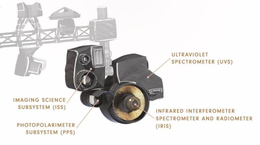
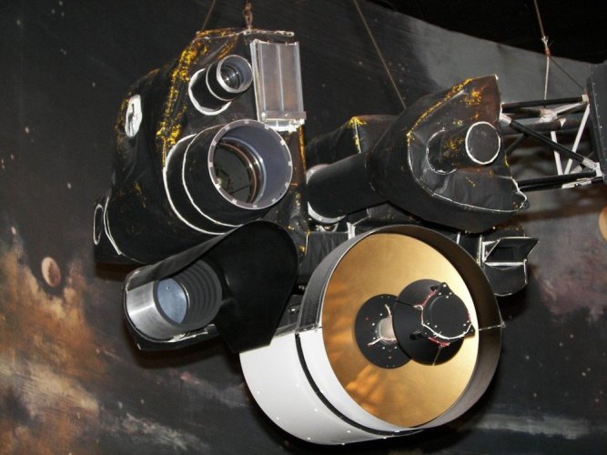
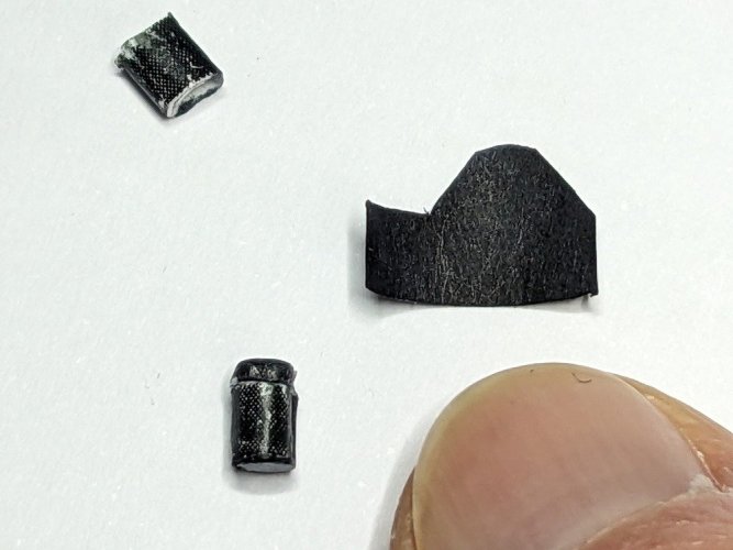
Greebling 2a: Photopolarimeter: This is a lot shorter than the model's version and has a shroud around about half of it. A few tries with some freehand cutting of paper, blackened with a Sharpie, cut some of the length of the original tube and we're in business. The finger for scale here is not a thumb, it's my first finger. I'll try to use a rule sometimes to show the scale of this, it's small!
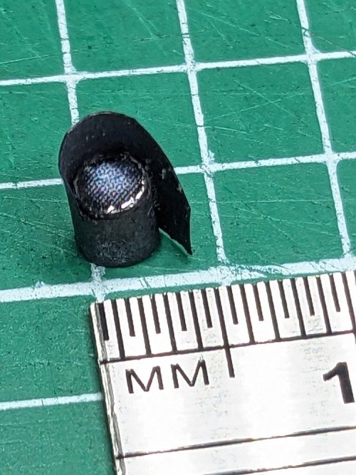
Wrap it around and it's not bad, especially at this scale. Once again, the modern phone camera shows all flaws in forensic detail. It looks nicer than this to the naked eye!

Researching 70s technology you realise just how few photographs exist of the original working spacecraft as they were intended to function in space. Most photos are from during construction, where sensitive equipment was often covered to protect from dust ingress until close to launch "packaging up", or from tests, or from display versions which again, sometimes have coverings etc. Or there are lots of diagrams which aren't quite true to the originals. I've based a few upgrades on these 2 photos.


Greebling 2a: Photopolarimeter: This is a lot shorter than the model's version and has a shroud around about half of it. A few tries with some freehand cutting of paper, blackened with a Sharpie, cut some of the length of the original tube and we're in business. The finger for scale here is not a thumb, it's my first finger. I'll try to use a rule sometimes to show the scale of this, it's small!

Wrap it around and it's not bad, especially at this scale. Once again, the modern phone camera shows all flaws in forensic detail. It looks nicer than this to the naked eye!

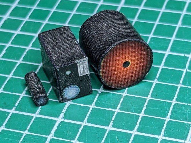
Greebling 2b: Imaging camera: This was asking for some lens hoods to make it more realistic. Cut, coloured and rolled a couple of rings from normal 80gsm paper, the smaller one is only 1.5mm diameter, rolled round a needle.
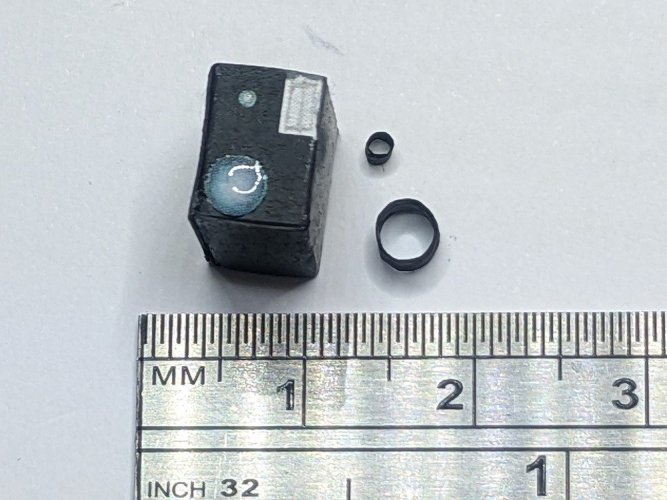
A quick dip on a smear of CA glue and they're on, really helps to make it look more like a camera with a couple of lenses.
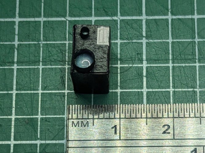

A quick dip on a smear of CA glue and they're on, really helps to make it look more like a camera with a couple of lenses.

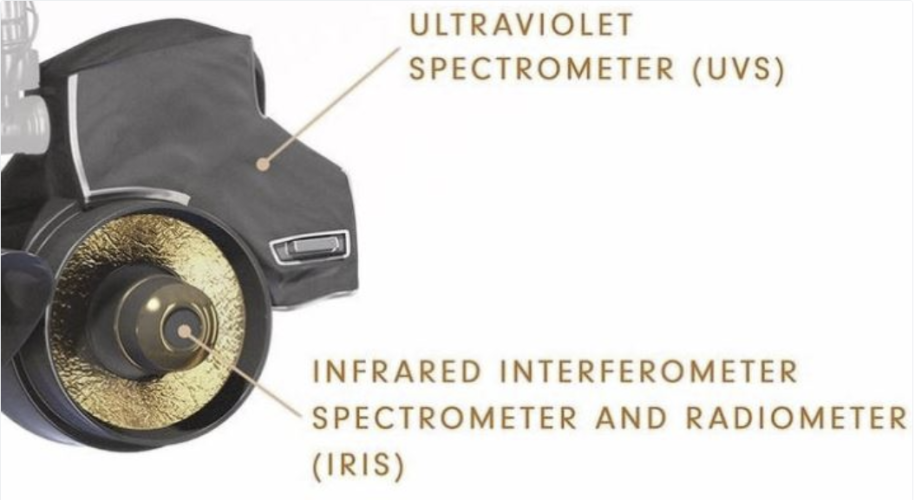
Greebling 2c: Spectrometer Assembly. From the photographs earlier and from the line drawing of Voyager in the model's instructions, it's clear that there are lots of interpretations. I chose to go for the general shape and connection to the instrument boom of this:
With the IRIS looking something like this (this is from an excellent set of photographs here (https://historicspacecraft.com/Probes_Outer_Planets.html):
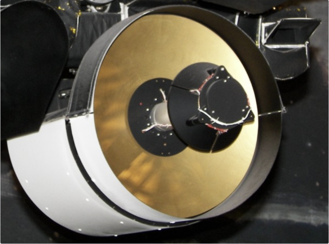
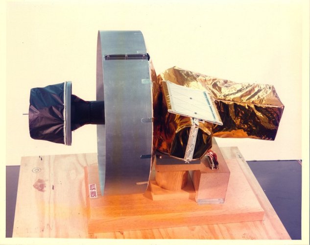
So ... modifying the basic shape of the piece holding the instrument from above, addition of a piece to the right, including the little wedge shaped addition to the UVS, and the construction on the front of the large mirror. It's possible that the back section of the white cowling behind the primary mirror is part of a protective shroud ejected a few days into the missions, as some photographs and illustrations are missing this, having the narrower ring in front of the mirror, but revealing more of the rest of the instrument's mechanism behind it like this (from https://www.ninfinger.org/models/vault2008/Voyager IRIS Instrument/index.html):
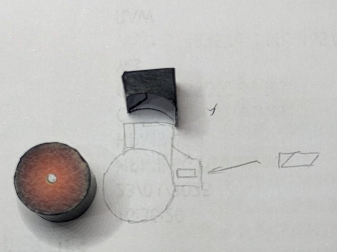
Too ambition for me at the moment, especially at this scale, so for simplicity here, I've gone with the shrouded version. A quick sketch of what I'm aiming for (the holding section above the sketch has already been doctored from the original which fully covered the whole width of the mirror and instrument assembly).
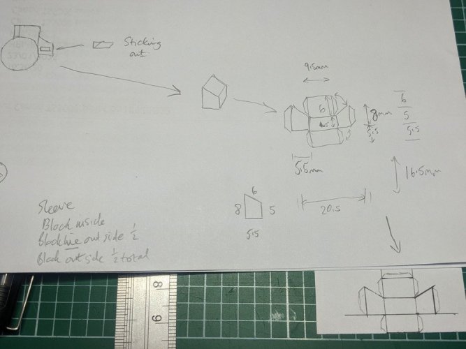
And then some more details and figuring out the shape of the side addition.
The top holder narrowed and the UVS body cut and assembled.
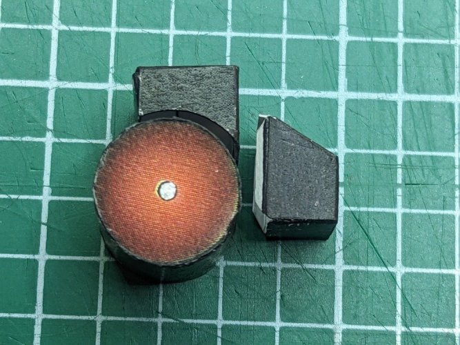
The Cosmic Ray instrument was handily the same shape as the front piece for the UVS, so with an additional piece to fill in the missing face, it could be persuaded to look the part.
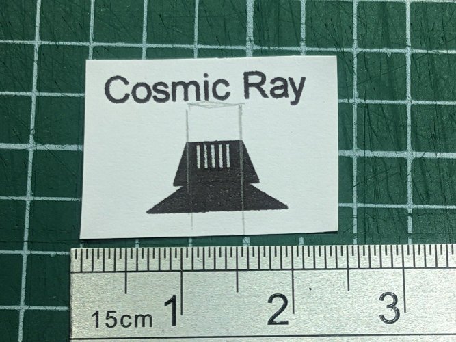
And here it is roughly assembled. In the picture there is white round a lot of the edges of this (I think it's a cover of some sort), so I've left it similarly in my version.
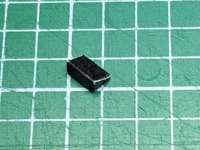
My cutting mat looks well worn! ️️

With the IRIS looking something like this (this is from an excellent set of photographs here (https://historicspacecraft.com/Probes_Outer_Planets.html):

So ... modifying the basic shape of the piece holding the instrument from above, addition of a piece to the right, including the little wedge shaped addition to the UVS, and the construction on the front of the large mirror. It's possible that the back section of the white cowling behind the primary mirror is part of a protective shroud ejected a few days into the missions, as some photographs and illustrations are missing this, having the narrower ring in front of the mirror, but revealing more of the rest of the instrument's mechanism behind it like this (from https://www.ninfinger.org/models/vault2008/Voyager IRIS Instrument/index.html):

Too ambition for me at the moment, especially at this scale, so for simplicity here, I've gone with the shrouded version. A quick sketch of what I'm aiming for (the holding section above the sketch has already been doctored from the original which fully covered the whole width of the mirror and instrument assembly).

And then some more details and figuring out the shape of the side addition.

The top holder narrowed and the UVS body cut and assembled.

The Cosmic Ray instrument was handily the same shape as the front piece for the UVS, so with an additional piece to fill in the missing face, it could be persuaded to look the part.

And here it is roughly assembled. In the picture there is white round a lot of the edges of this (I think it's a cover of some sort), so I've left it similarly in my version.

My cutting mat looks well worn! ️️
Greebling 2d: IRIS instrument itself: Adding the collector in front of the mirror and the shroud around it all.
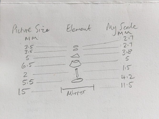
I planned to build the collector from a circle of card on the mirror, the mount column, an inverted cone, then a curved triangle and 2 more circular layers to build at least something like what I can see in the photo. Then I'd wrap a white/black paper shroud around the entire cylinder and then glue all the pieces together.
I did some calculations measuring the various parts from the image on my computer screen, then factored them for the size of my parts. All numbers are in mm.
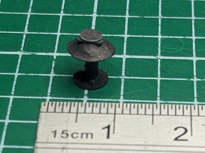
The mount was a sanded down cocktail stick painted with silver paint originally from my reference photo but the more I thought about it and having seen the photo without the shroud, I reverted it to black (probably partly to avoid reflected waves polluting images. All the rest was the 160gsm card I've used for the rest of the model. The collector assembly is a bit difficult to see as it's so small, but the triangular bit is there behind the top circles, sat on top of the inverted cone. Not the best, but better than nothing I think.

The full collector section assembly. It looks like a miniature table lamp
Worked out how to create the IRIS shroud with all the bits of black and white. Ended up creating a little Word document with the required part in for printing. Here's the shroud wrapped round the IRIS. I used 140gsm matte photo paper for this because running the Sharpie over the paper edges doesn't bleed compared to the normal card stock I've used elsewhere, and for this part it's important not to have that bleed onto the white lower section.
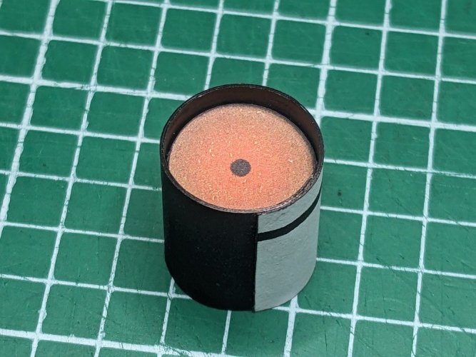
And with the collector assembly added.
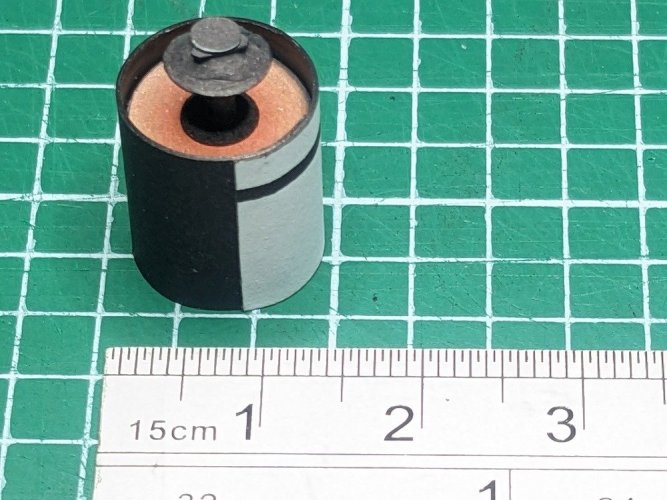
All the pieces of the IRIS and UVS assembled together with a before shot for comparison. Not looking bad, given the scale of this thing!
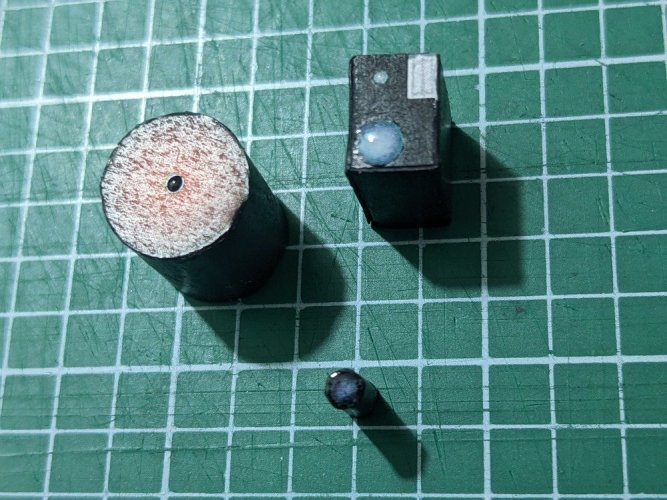
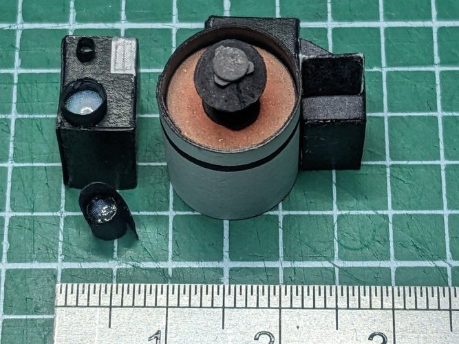
That'll do for now. A few nice enhancements so far. I can already see potential improvements to some of the other small instruments, but I might need to resist the urge to do much more greebling or I may never finish this model! Plus I still have to decide what I'm doing with that 25cm Magnetometer arm - seems a shame not to see if there's any potential to improve that.
I planned to build the collector from a circle of card on the mirror, the mount column, an inverted cone, then a curved triangle and 2 more circular layers to build at least something like what I can see in the photo. Then I'd wrap a white/black paper shroud around the entire cylinder and then glue all the pieces together.
I did some calculations measuring the various parts from the image on my computer screen, then factored them for the size of my parts. All numbers are in mm.

The mount was a sanded down cocktail stick painted with silver paint originally from my reference photo but the more I thought about it and having seen the photo without the shroud, I reverted it to black (probably partly to avoid reflected waves polluting images. All the rest was the 160gsm card I've used for the rest of the model. The collector assembly is a bit difficult to see as it's so small, but the triangular bit is there behind the top circles, sat on top of the inverted cone. Not the best, but better than nothing I think.

The full collector section assembly. It looks like a miniature table lamp

Worked out how to create the IRIS shroud with all the bits of black and white. Ended up creating a little Word document with the required part in for printing. Here's the shroud wrapped round the IRIS. I used 140gsm matte photo paper for this because running the Sharpie over the paper edges doesn't bleed compared to the normal card stock I've used elsewhere, and for this part it's important not to have that bleed onto the white lower section.

And with the collector assembly added.

All the pieces of the IRIS and UVS assembled together with a before shot for comparison. Not looking bad, given the scale of this thing!


That'll do for now. A few nice enhancements so far. I can already see potential improvements to some of the other small instruments, but I might need to resist the urge to do much more greebling or I may never finish this model! Plus I still have to decide what I'm doing with that 25cm Magnetometer arm - seems a shame not to see if there's any potential to improve that.
Last edited:


