Liebherr R-954 Excavator by nosports and Retunga
- Thread starter Boris
- Start date
You are using an out of date browser. It may not display this or other websites correctly.
You should upgrade or use an alternative browser.
You should upgrade or use an alternative browser.
Hi all
I am back with only small update. I am in process of making hinges.
Hinges are the parts that connect to the arms and allow arms to move relatively
The build method is, again, interesting. Each hinge (except Hinge 4 which is actually a connection rod cover) is made of two small tubes that will hold the pins, external and internal parts. The idea is to partially make the external part, create tubes around defined radius (I used my wife's knitting needles which I think every builder should have. I mean knitting needles
 ), then need to install the internal part. Afterwards, need to align and install the tubes. And then need to close external part, trying to align everything. This process is very time consuming for me. There are another ways to make these, (for example the one proposed by Yoav Hozmi, my good buddy, where no holes and tubes should be made and cardboard laminated side cheeks should be connected with thin wires hidden afterwards) but I will stick to a originally proposed system
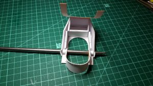
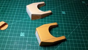
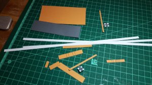
I tried to show the build process of one of the hinges, I hope it is seen well.
4 hinges gone, 3 to go


I am back with only small update. I am in process of making hinges.
Hinges are the parts that connect to the arms and allow arms to move relatively
The build method is, again, interesting. Each hinge (except Hinge 4 which is actually a connection rod cover) is made of two small tubes that will hold the pins, external and internal parts. The idea is to partially make the external part, create tubes around defined radius (I used my wife's knitting needles which I think every builder should have. I mean knitting needles

I tried to show the build process of one of the hinges, I hope it is seen well.
4 hinges gone, 3 to go


Hinges are fun!!! but I take the rolled ones and roll a length of printer paper around a wire I am going to use as the pin... then cut the rolled tube around the wire into 3 or 4 equal parts assemble the parts to be hinged and place the rolled sections with the wire in place in the proper location and a drop of superglue under each section of tube...just have to be careful!!! I think after typing this a tutorial would be handy...will see what I can do...as I have made all sorts and types of hinges..and pictures are better than words!!
Hi
I know this method.
In this case the gluing tabs serve not only as internal reinforcement of narrow paper strips around the holes thru which the tube goes, but also act as a spacer that helps in positioning of side cheeks. This is a very good idea. I thought of other ways also but the proposed way looks reasonable
Hello everybody
Alrighty, finished the hinges. All parts that their edge is seen were laminated onto cereal box cardboard and edge colored to make it look in scale .
Then I switched to bucket, i.e. the main feature of any digger.
No special trouble here, instructions are pretty clear. One thing that went badly,
was incorrectly installed teeth, which I managed to fix later. Here I also laminated the side cheeks and the side cheeks reinforcements. Just to make it look in-scale
Some pictures...


Hello everybody
I realized that I did not write anything for almost 2 and a half months
Partly because we moved to other house and it took some time to recover, partly because the digger was damaged during the moving.
So, new update.
Had to remake the hinge number 1 again because of previous one was damaged
The damage is seen on the picture below
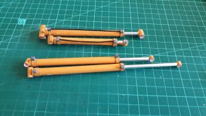
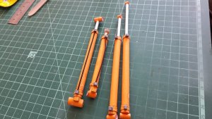
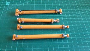
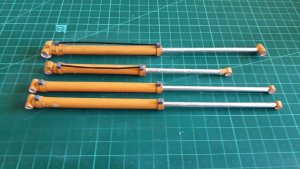
And then I continued to hydraulic actuators (pistons)
Each actuator is constructed from
Front small tube
Aluminum cover for the front tube
Rear large tube
Three stopping rings that allow internal tube move into external one
Two end connectors
Two rings that sit on the external tube
Front and rear hydro line connectors
A stop block (only on two actuators)
Hydraulics tube made from PVC covered paper clip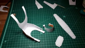


Top work.
Tubes! Arghhhh!
You've really done a splendid job of those.
Getting uniform cylinder shapes is so much harder than you would expect. (Well it is for me.)
Great work. Claphands
Tubes! Arghhhh!
You've really done a splendid job of those.
Getting uniform cylinder shapes is so much harder than you would expect. (Well it is for me.)
Great work. Claphands
Thanks!!!Top work.
Tubes! Arghhhh!
You've really done a splendid job of those.
Getting uniform cylinder shapes is so much harder than you would expect. (Well it is for me.)
Great work. Claphands
The biggest trick here was to use knitting needle
It really simplifies this tube making process
I already mentioned that I constantly raid my wife's knitting supplies. But, if these supplies are not available, a good set of aluminium knitting needles costs close to nothing on Ebay, Aliexpress, wish or any other platform. This is the best thing to buy for building paper models
Hi all
More update.
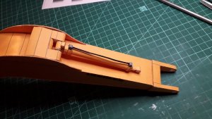
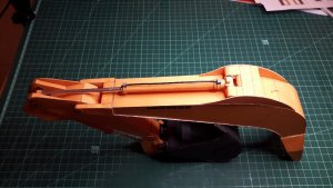
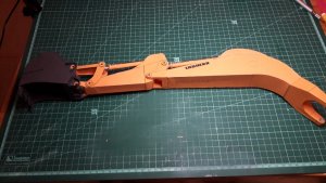
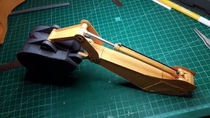
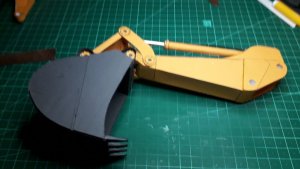
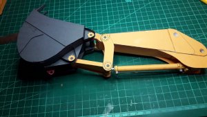
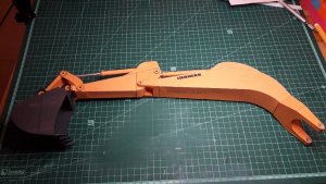
Started with digging arms assembly
First I joined the Arm 1 (I.e. the boom) with its hinges. Then I glued in the hinge and the axle for the boom to stick hydro actuator with the actuator
Then came the Arm 2 (I.e. the stick) with its hinges.
Afterwards the hinges and the side cheeks for stick to bucket actuator with the actuator were installed.
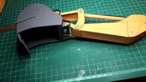
Then the bucket was installed on its axle, followed by connecting arms for the bucket.
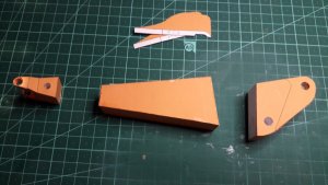
I must mention that almost all axles had to be remade from scratch. As I noticed earlier, I used thicker paper than suggested by designers. I also laminated some parts with 0.6-0.8 mm cardboard to make them look in scale. This brought to some axles being too short or too long. Also hinges 2 and 7 became too wide and had to be cut in two and narrowed by removing 2 mm strip from the middle.
Then i tried to dry-fit the parts only to realise that the hydraulic actuators were mixed between. The actuator 3, the long one should be on the boom moving the stick and the actuator 4 should be mounted on the stick moving the bucket.
Removed the hinges 2 and 7, axles, actuators and reinstalled everything in the right way.
Finished assembly by connecting all the bucket linkages, axles and hinges and then mounted the stick on the boom.
Then I connected the main actuators numbered 1 and 2 to their upper hinges
I must say that although the instructions are really clear explaining the sequence of assembly, need to be careful with numbering of the parts and axles. Need to understand exactly what is done now. Nothing too hard for builder with some experience
Sme pictures below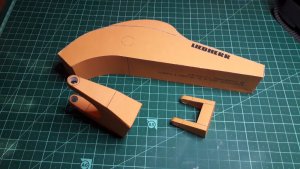
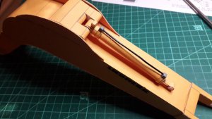
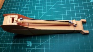
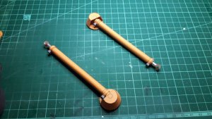


ThanksThat's looking real good! Big too!
Nice work.
Looking forward to seeing this get put together.
The model is really big.

