So...its all in the hips (so they say

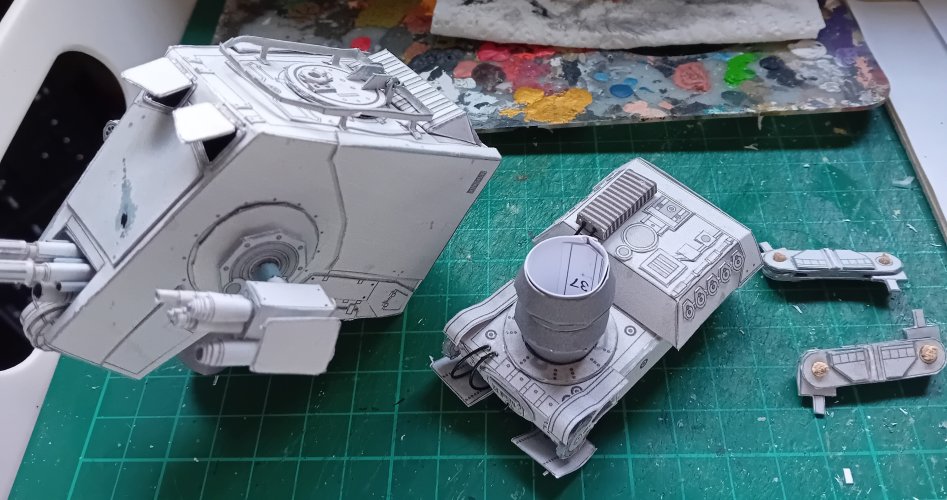
) The hips, having dried well enough, were ready for fitting to the torso. Here is where i had an interesting 'oh!' moment *for the record, this conversation has been pre approved by the almighty designer and occasional host of the shrinkray, Mr Revell Fan, designer of this very kit) So get comfy, get a coffee, and listen ye to a tale
....dragons....knights.....oh, err, wrong narrative lol

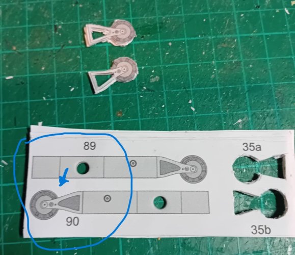
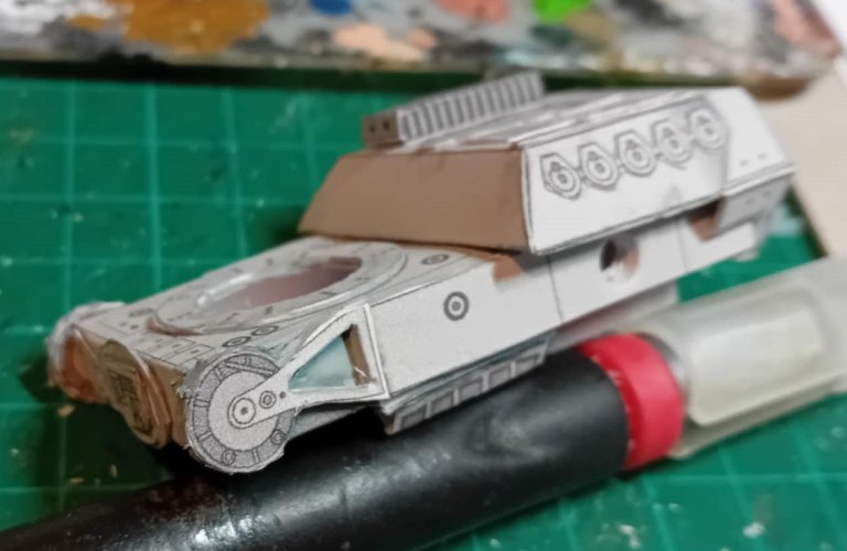
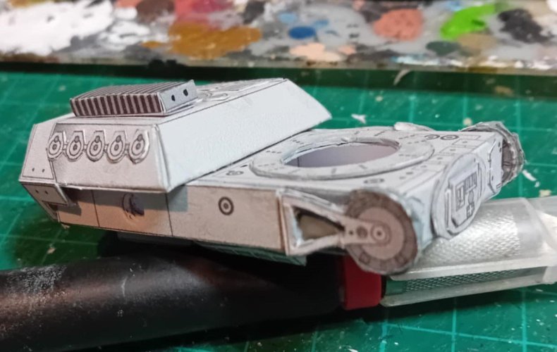
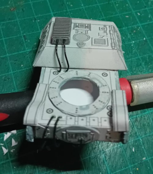
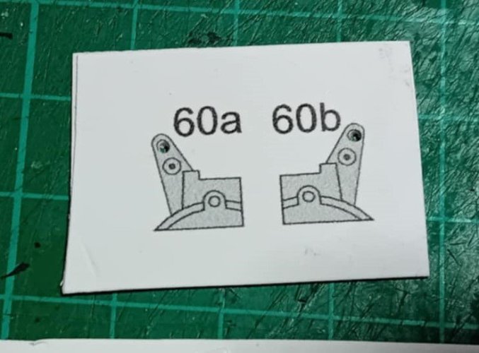
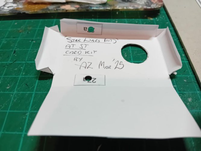
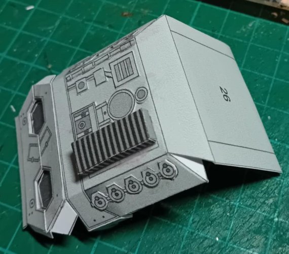
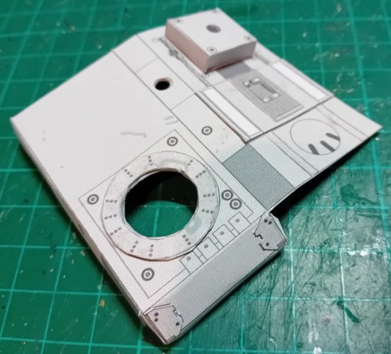
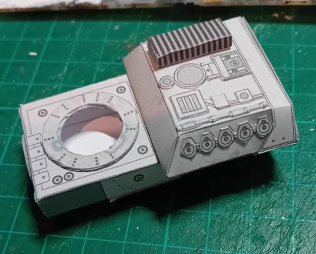
So back when we are putting the torso section together (part 27) we are directed to punch a hole in the sides (via adding strengthening part 27a on the inside 'side') ready for when the hip brackets will be added later - we then do the same again to the secondary outer 'sides' 89 & 90 which fit over the previously cut holes (see pics) Then once the torso is all finished we move on to the hip brackets - parts 45, 46, 48, 49 and parts 47 x 4 for the small bracket/hinge - one of these will fit to the torso on either side, the other to the top of the legs. As youll see in the pictures part 47 has a small flat tab on the end, which is attached to either the torso or leg (
here was my OH! moment) looking at the hole i had punched into the torso previously - then the tab on the hinge (47) i realised this was a
flat tab fitting to a
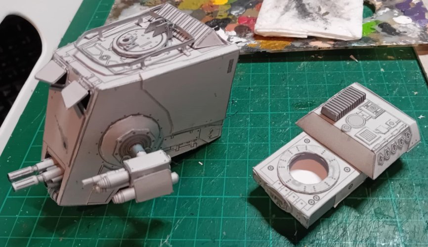
round hole. Hmm. My worry was that (knowing me) i would fix the flat tab into the round hole, put the legs together, and the whole thing would crumple. (quickly
messages to our very own Revell Fan to see if this was just me being mental or a design thingy)
Having had a chat and bounced some ideas about, i came up with a way that (may) help resolve this issue for future builds, if anyone needs it.
So........on to the MacGyver moment...
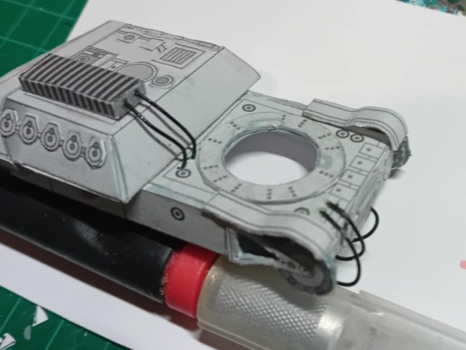
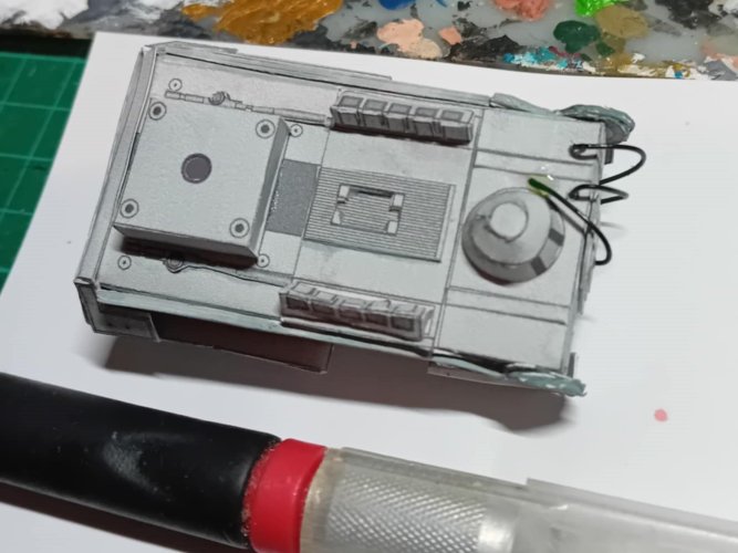
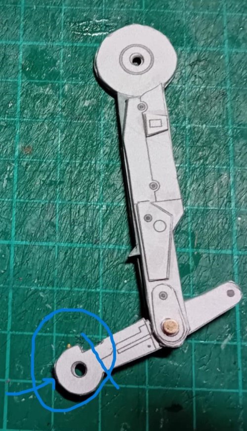
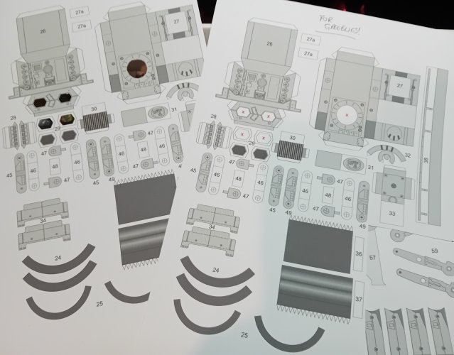
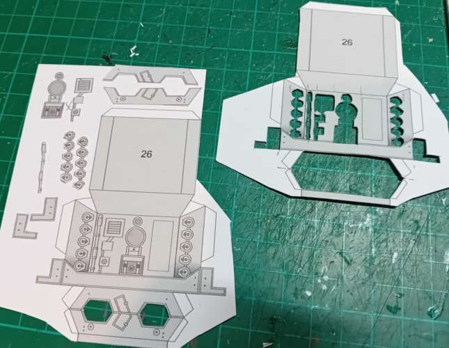
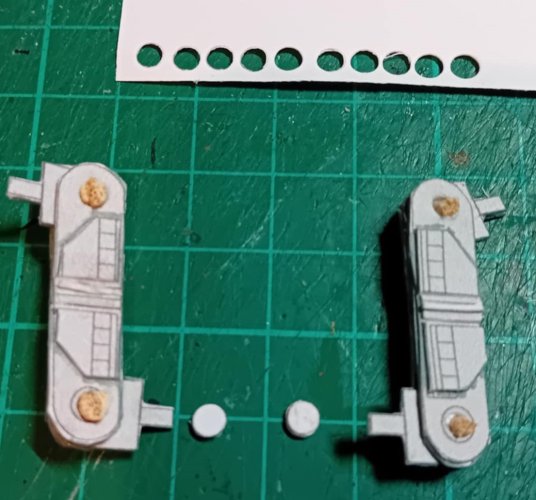
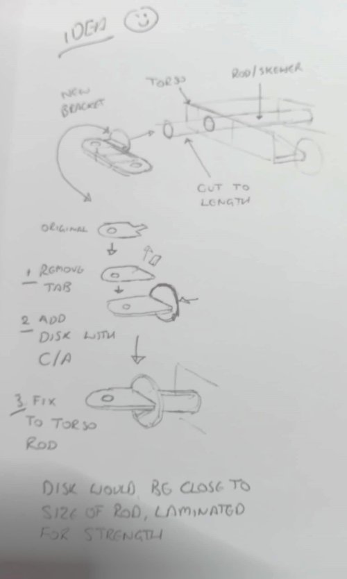
The holes through the torso line up - so (one) idea is to push an appropriate size rod through and cut to size (almost flush/flat) to the torso - cut the small tab off part 47 where it fits to the torso, and fix this instead to the rod with a strong adhesive like C/A. Another is using card, punch the same size hole used for the one in the torso - but using the
discs created, laminate about 4/5 together so it forms like a 'plug' once dry, cut the tab from part 47 and attach them at a 90 degree right angle with a strong adhesive like C/A - once dry again using C/A fit the 'plug' into the hole at the desired angle/pose and let dry well. (you can also just cut a small length of rod for the same purpose)
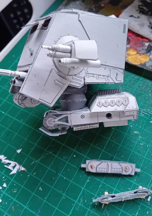
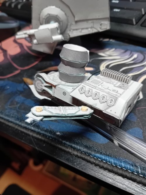
As you can see from the pics i used the laminated card method, which seemed to work pretty well for my purpose. Im sure there are plenty of other easier methods that could be used, but in a pinch this is what i thought of lol

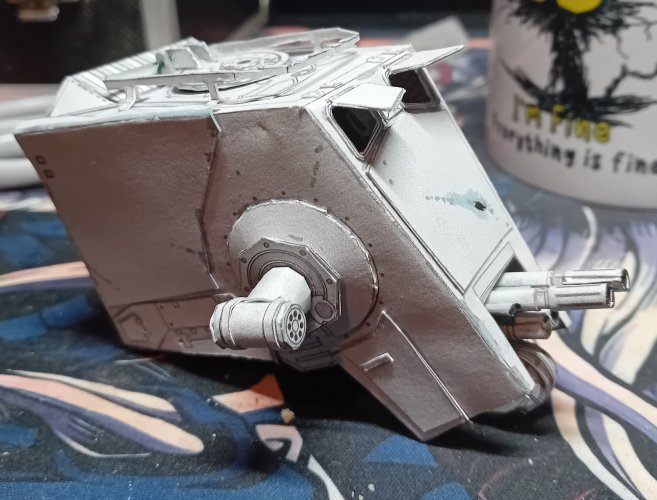
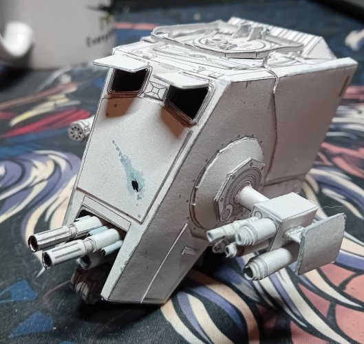
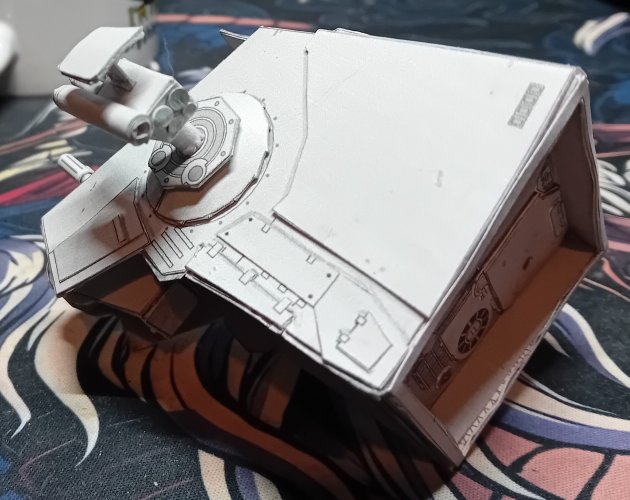
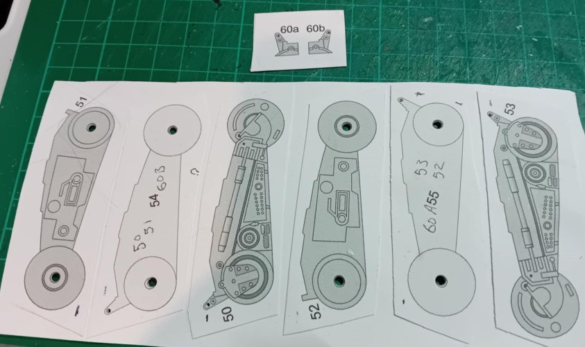
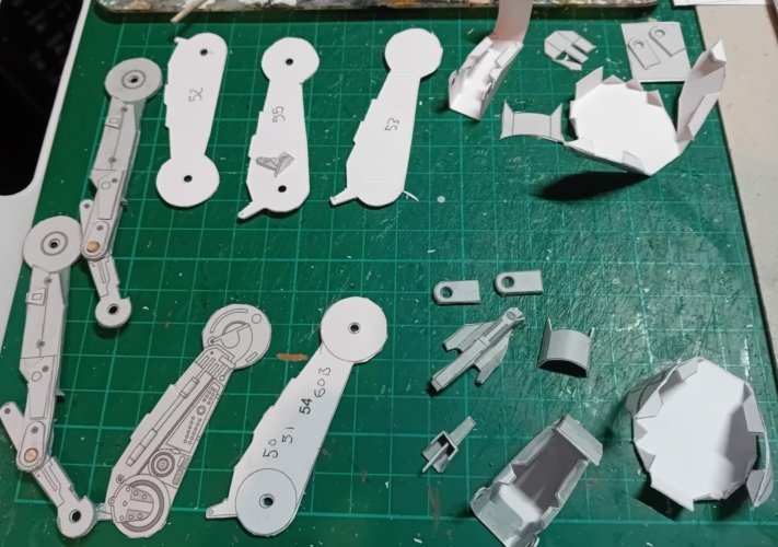
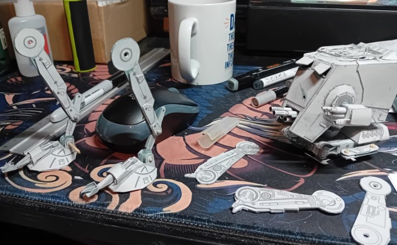
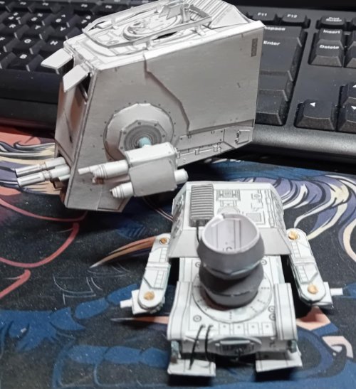
Anyway, here are some progress pics, including a cpl for the lower leg parts (which follow the laminating process and uses spare copies for greeblying)
I hope my waffly explanation/adaptation helps, again this was just my idea for this part and hope it helps


")
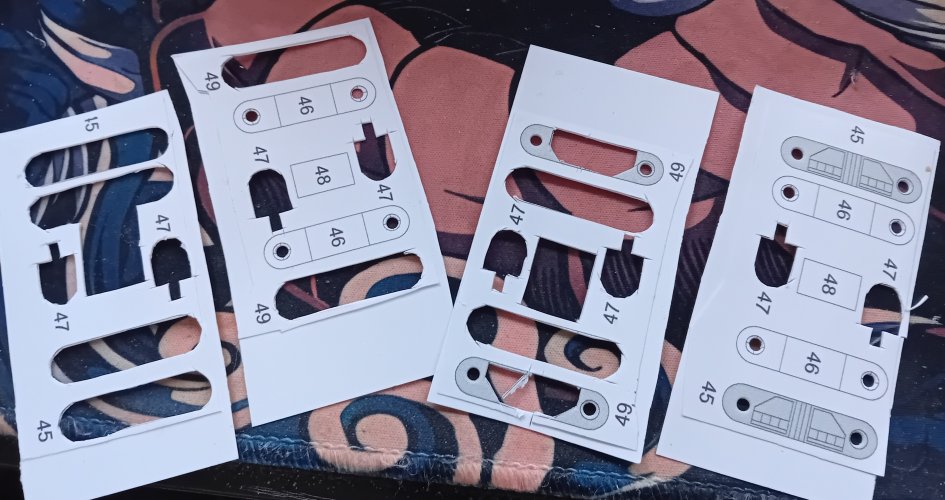
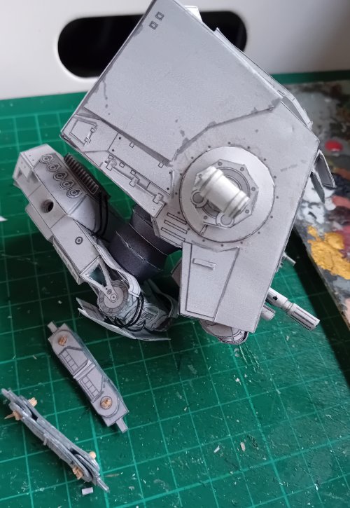
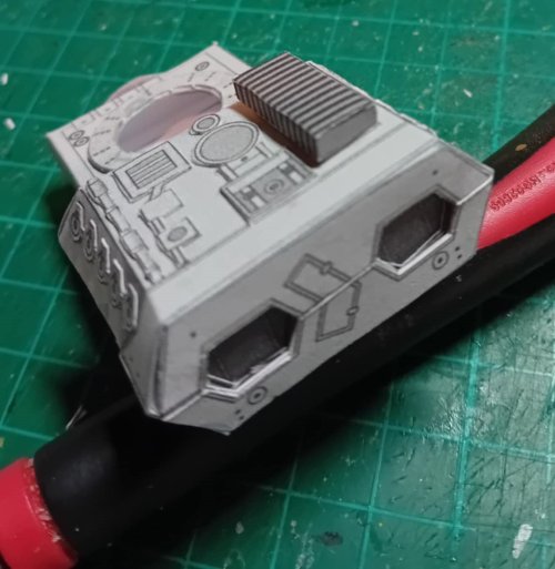
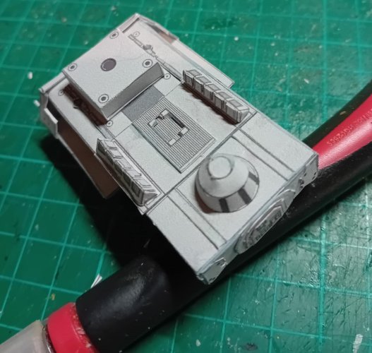
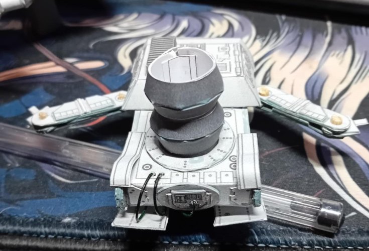
 i laminated both sides twice, and also did a second spare set too. Once all the parts were dry they were hole punched, cut, and glued together. Once i was happy that the brackets fit fine i used the spare copies to just add a little 3D detail to the panels, tidied them up with acrylic markers, fit the brackets in place, then added the rods (small skewers) cut them to size, and done. Theres a cpl pics to show the progress so far while i get cracking on the legs lol
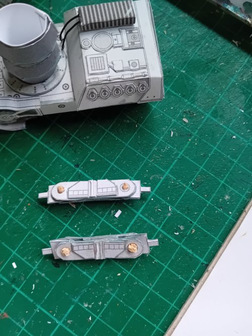

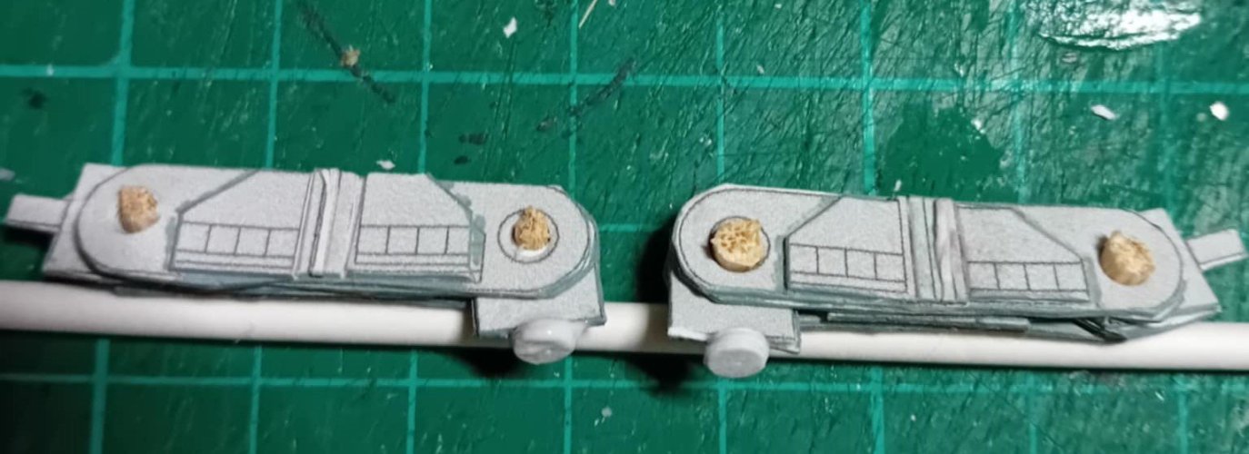
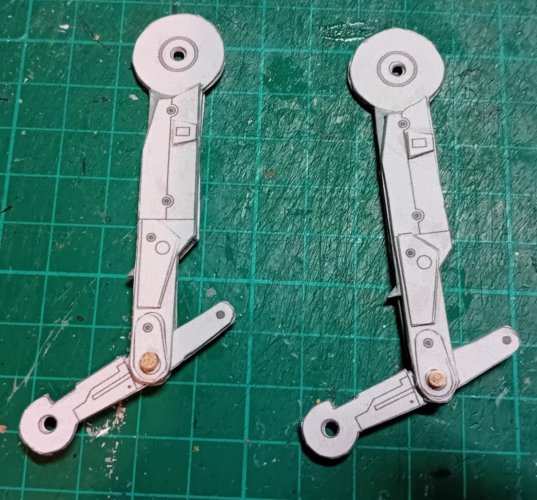
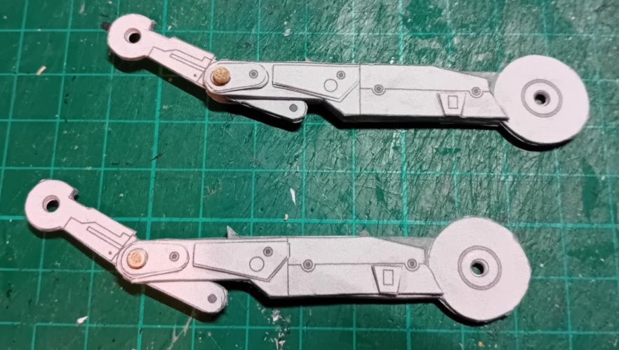
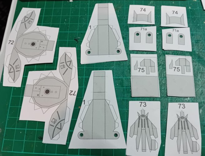
 being put together are the two feet - these were laminated a cpl times for a bit more strength, cut, scored, hole punched and readied for final building while working on the 'ankle' joints - these parts (71a) require more laminating to make the lower leg (58/59) to sit snugly between them, so ive ended up laminating them up to about 3mm just to make sure they are a tight fit - once im happy with the pose all the joints will be glued for sturdiness.