Crane - Panther X250

Sky Seeker

Well Established Member
Here's a vehicle that I ran across while looking at the Canon papercraft site, which has literally hundreds of papercraft models there for beginners and more experienced modellers.

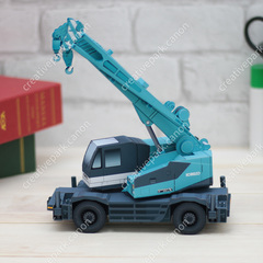
This is the Panther Crane X250. Created by K.Yoshinaka. Found here:


1579648218414.png 1579648394784.png 1579648409393.png


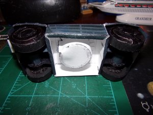
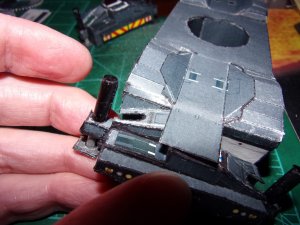
This model has lots of parts that move and some greebling opportunities. It looks like it will be an interesting challenge! A bit of a deviation from the usual sci fi items that I normally build. I guess it falls in line with learning how to weld structural steel as well as other construction items. Interesting stuff for sure!

Sky Seeker
 

Revell-Fan

Co-Administrator
Staff member
Administrator
Moderator
I like the fact that the construction vehicles are articulated. That gives them so many display options - and they are fun to pose. :)
 

Sky Seeker

Well Established Member
Hey everyone! Here's an update on the crane.

Chassis base with center turret holder.
1583027803991.jpeg

1583027886205.jpeg
The top edge gas the red squares on top while the bottom is mounted on top of the green squares. Note the black edge treatment done with marker to remove white glare.
1583027933222.jpeg

Note the bottom of the turret
1583028038895.jpeg

1583028160799.jpeg

Main chassis
1583028206108.jpeg

1583028260766.jpeg

1583028296026.jpeg
Note the raised front tabs that will receive the wheel wells.
1583028326400.jpeg

Wheel wells to the right and wheel axles to the left.
1583028387231.jpeg

1583028461262.jpeg

Closeup wheel well edging. note that the lower flaps are NOT glued to the body yet.
1583028484462.jpeg

First wheel well attached. Note also that the turret is joined to the chassis in the center.
1583028576810.jpeg
Bottom view. Flaps are folded and glued in place. In gluing the flaps a weight was placed on top of both of the flaps to maintain and form a straight flap otherwise they would buckle.
1583028665634.jpeg

The other wheel well before joining with the chassis.
1583028805888.jpeg

Center chassis tabs joined to wheel well.
1583028863721.jpeg

That's it for now.

Sky Seeker
 

zathros

*****SENIOR ADMINISTRATOR*****
Staff member
Administrator
Moderator
I like these models. They areable to be posed, interesting to look at, as they are unusual, in the sense of you just don't see models like this sitting on the shelves of people's houses. :)
 
Last edited:

Sky Seeker

Well Established Member
This looks like it would be a fun project to tackle.

Rhaven,

Sorry I haven't responded earlier. Life got busy and I finally got a chance to get back into this model. The part I'm working on now is the wheels which have 7 parts per wheel which form the hub and the wheels themselves. Will post the pics when I'm done with the wheels. Both wheel wells are attached to the chassis now. Just forgot to upload a pic of the assembly. Will do so after the wheels are finished.
 

Sky Seeker

Well Established Member
I like these models. They are posabble, interesting to look at, as they are unusual, in the sense of you just don't see models like this sitting on the shelves of people's houses. :)
Yes. That's why I'm tackling this model. It's outside of the normal Sci Fi mold and a little more down to earth. There are a LOT of little parts to this, but it's NOTHING in comparison to some of the tank models out there with over 10,000 pieces. I think I would lose my mind working on the links.

Have a great day!

Sky Seeker
 

zathros

*****SENIOR ADMINISTRATOR*****
Staff member
Administrator
Moderator
You cann still greeble up the tracks, even by adding squares, to differentiate the tracks and give some texture to them. Lots can be done to bring some more life into these models, which I am sure you already know. . ;)
 

Sky Seeker

Well Established Member
Hey everyone. It been a while since there's been any posting regarding the model. Here are some pics showing the wheel construction, which was slightly more involved than most wheels for a lot of the models out there.

1595172772442.jpeg

Wheels - outer inset hub - Note the edge coloration on the circular portions.
1595172792517.jpeg

Wheels - outer inset hub - assembled
1595172869728.jpeg

Wheels - outer inset hub - close up - backside tab folding. Make sure to apply pressure from the front and apply glue to the tabs and fold around then apply pressure on both sides.
1595172925937.jpeg

Wheels - outer inset hub - assembled - pieces of inner hub before assembling
1595173107139.jpeg

Wheels - inner inset hub - lower portion of pic
1595173230538.jpeg

Wheels - inner hub assembled -before application to outer inset hub portion
1595173518814.jpeg

Wheels - outer edge - cut templates
1595173609364.jpeg

Wheels - outer edge - colored edges
1595173643830.jpeg

Wheels - inner and outer edges joined together. Inner hub assembled to outer insert hub
1595173768249.jpeg

Wheels - front inner and outer edges joined to inner hub assemblies. Backing cut with edges cut. Joining the inner hub asseblies was a little tricky due to the inner circular portions having to be bent inwards while being connected to the inner hub assembly and trying to maintain the inner hub centered. Recommend in future builds to add the inner hub LAST to the wheel assembly.
1595173871542.jpeg

Back portion of wheel folded and glued together to for the tire tread.
1595174264260.jpeg

Front view
1595174280839.jpeg

Inner hub and tire tread and backing assemblies joined together. When gluing the back flap to close the wheel assembly try gluing the edges together in stages and NOT all at once due to lining up the tire treads with the edges of the circular back portion.
1595174484806.jpeg

That's it for now.

Sky Seeker
 

Attachments

  • 1595172815685.jpeg
    1595172815685.jpeg
    546.5 KB · Views: 0

Sky Seeker

Well Established Member
Chassis with wheels

1595289778199.jpeg

Bottom of chassis - as can be seen everything is white with no coloration.
1595289814481.jpeg

Axles for wheels - Note that the inside portion of the axle supports have been colored by a black marker.
1595289904573.jpeg

Axles - Note that the wheels have been glued and fully assembled. The axles have been inserted through the axle supports with the outer section extending through the support covered by rings (see right side with right support).
1595290035306.jpeg

Chassis - The wheel wells are colored in to reduce glare. Also it permits location of the axle supports.
1595290292912.jpeg

Chassis - all wheel wells colored in.
1595290405776.jpeg

Wheel axles assembled. Wheels are joined to the axles with the rings positioned first about the axles, then the wheels are attached. While this looks easy to do, making sure that each wheel matches up with the same level on the opposite side while being centered can be difficult. What was done was that one wheel was attached and centered. The other wheel was attached on the other side while rotating the axle support so that both wheels can contact the surface. Move the second wheel until it is level and centered with the other wheel. Then let the glue dry while holding (it doesn't take long). Note the tire treads. When looking at the model with out the flash you can't see the tire treads. Additionally, you can't see the tire separation either.
1595290468438.jpeg

1595291167065.jpeg

Wheel / Axle support assemblies joined to the underside of the chassis. You can color in the ends if you wish they were left white to see if the axle supports were properly lined up.
1595290867140.jpeg

Chassis with wheel / axle assemblies. In assembling the wheels some of the sidewalls were accidentally manhandled and therefore gave a crushed in appearance with cracking of the sidewalls. The wheel hubs were then colored in by a black marker to eliminate some of the appearance of the crushed in areas.
1595291188125.jpeg

That's it for now.

Sky Seeker
 

Attachments

  • 1595291228606.jpeg
    1595291228606.jpeg
    557.5 KB · Views: 1

Sky Seeker

Well Established Member
Hello everyone,

It's been a while. Have been learning how to MIG weld and have been getting involved in other life projects. Ok onto the Panther Crane...

Side support struts

Template - holes cut out with a leather punch cutter. The paper on the side is used as a reference for the size of the holes and what punch to use.
1603837519392.jpeg

Outer strut assembly assembled. The black post section was originally gray then colored black with a marker. The bottom of the post has upturned edges that are glues inside of the forwardmost portion of the strut. The gray struts (hydraulic jacks) were rolled between fingers, then colored by a silver marker. The bottom rectangular portions on the bottom of the picture were punched out and slid onto the bottom of the gray struts to form a "hydraulic piston".
1603837674176.jpeg

Hydraulic jack slid through the punched hole in the rectangular piece to form a foot.
1603840200913.jpeg

Hydraulic jack assembled and assembled to form the moveable strut (yes the strut moves - it is NOT glued in place inside of the black post)
1603840301802.jpeg

Hydraulic jack assembled - retracted
1603840406155.jpeg

Hydraulic jack assembled - retracted
1603840470623.jpeg

1603840511998.jpeg

Strut receiver - note that the right hand side is folded back and glued in place and a "U" shape cut is made at one of the pieces on the right hand side.
1603840551290.jpeg
Strut receiver - note the tabs are folded inside of the area that receives the support strut
1603840655670.jpeg

Struts positioned inside of the strut receiver. Note that there are two receivers for left and right struts. The top strut receiver is joined to the bottom receiver. Note the "U" shape cut is there to receive the piston assembly of the hydraulic jack.
1603840754129.jpeg

The top strut receiver is joined to the bottom receiver. Note the left side tab overlapping the right hand receiver.
1603840973000.jpeg

Struts extended away from the stut receiver with the hydraulic jacks extended.
1603841050493.jpeg

Two pairs of strut receivers joined together. All pieces are retracted. One has a rear bumper attached and the other has a fornt bumper to be attached.
1603841191855.jpeg
Front bumper with additional piece attached the fold for this was pretty tricky to do and wasn't very obvious.
1603841317525.jpeg
Front view of the front bumper attached. Top down view of the rear assembly. You can see how the top piston portions are received within the strut receivers.
1603841433955.jpeg
Strut assembly extended with hydraulic jacks extended (front view).
1603841569368.jpeg
Strut assembly extended with hydraulic jacks extended (top view).
1603841625616.jpeg

That's it for now.

Sky Seeker
 

Sky Seeker

Well Established Member
Attaching the strut assemblies to the main chassis.

Note the rear central tab extending from the front of the chassis. This is glued on top of both of the strut assemblies. Also the back of one of the assemblies is attached to the main chassis. Lining up these assemblies can be challenging.

1604638730511.jpeg
Tab glued on top of both strut assemblies.
1604638730511.jpeg
Tab glued on top of both strut assemblies. Side view

1604638819482.jpeg
Front view of strut assembly joined to the front of the chasis

1604638903596.jpeg
Rear view of chassis with second strut assembly attached.
1604638926334.jpeg
Both strut assemblies attached to the chassis. Side view.
1604638986083.jpeg
Top view - Both strut assembles extended with jacks lowered.
1604639119660.jpeg
Front view - Both strut assembles extended with jacks lowered.
1604639172172.jpeg
Side view - Both strut assembles extended with jacks lowered. The jacks can lift the vehicle up and there's enough friction with the jacks to suspend the tires off of the surface.
1604639226329.jpeg

That's it for now. Onto the boom of the crane!

Sky Seeker
 

Attachments

  • 1604638635128.jpeg
    1604638635128.jpeg
    530.1 KB · Views: 1
Top