Blackadder's Imperator Titan Build

Blackadder

Well-Known Member
Blackadder Attempts to build an Imperial Warmonger Titan:

Well a good many of you know by announcing this I have a fair idea of how I am going to proceed with this build but we also know we're gonna be in it for the long haul. Now that FW has released a Warlord (I'll buy the Chaos version when they release it because Chaos and the sculpted organic hulls and carapaces go well together in my opinion) but the Warlord Mars and Alpha not so much; also IMHO. Anyway it's always been in my mind to build a transport companion for my Warlord perhaps a foot taller with ruddy great greaves and threshold steps and Imperium Aquila doors to release a few hordes of grunts. I figure my Emperor titan to be on the order of 80 CM/32 inches tall.

This build will be much more of a static model than any of my previous efforts as I have seen the classic Emperor Titan and they look best with legs spread and threatening and it's just too much work to repeat all the leg articulation.

img4a1ebdec2854a.jpg

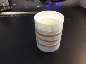
So this past winter I've been collecting parts and formulating my ideas and with this last Amazon purchase of a 'Sanctum Imperialis' building I am ready to begin the build starting with the greaves and feet.
 

Blackadder

Well-Known Member
Thanks for the reply

Lucius Patten Imperator Titan 'Invictus'

So with the blurb ten months ago about my proposal to begin an Imperator Titan I kinda fell flat on my face.

First, finishing up the Thunderhawk monopolized a good deal of my time and learning how to best incorporate lighting in said Thunderhawk and my Warlord engaged yet more time. Then the Presidential election captured my attention almost to the exclusion of all things else. Finally I have returned to normalcy with what I consider a fabulous idea to make a hip and lower torso mount commensurate with an automaton of this magnitude.

So we shall begin with the 'pelvis' which I found ready made on my local Lowes Building center where I purchased about six bucks worth of PVC pipe fittings A compression fitting Tee, a threaded coupling for the connection to the upper torso and two more for the hips connections.

1.jpg

Naturally all this is quite utilitarian and looks exactly what it is, some pipe fittings and there are many titans that follow this procedure and leave the fittings as is. I intend to flesh out the assembly in styrene so as to hide all the piping that will only serve as an armature or skeleton for the model.

In the image below you will get an idea of how much more robust this construct will be compared to the pelvis and hips of my Warlord.

2.jpg

Where as Luteus Vexant has hips trunnions about an inch in diameter 'Invictus' shall have 1.5 inch axles.

The beauty of this ready made construction technique is I shall be able pivot the waist and separate the model easily and hopefully allow the legs to be posed in a walking position as well as the spraddle-legged pose.

3.jpg
 

Blackadder

Well-Known Member
Thanks for all the replies, these Emperor Titans must be popular.

Basic Pelvis Block Complete:

With thsi post the basic pelvis is complete. All that is left is applying the detail. I may bevel the corners and edges to add more pizzazz as I did on the Thunderhawk but all that is cosmetic.

zJQSzyE.jpg

The Epic Imperator is very plain and you can let your imangination run wild with the amount of detail a 3 foot tall model requires. I have a good stock of City of Dead panels left over from my Warlord and I have a Fortress of Redemption to decorate the greaves if needs be.

2oMX14M.jpg

I used 0.040 thousandths styrene to sheath the pelvis and sanded the edges smooth; there's not really much to say about the step except to take great pains to make your angles square and true. Good enough is never "Good Enough"; that's my motto.

PUPtHYJ.jpg

A few extra pains taken now will save you a lot of grief later.

Jp3YsLu.jpg
 

Blackadder

Well-Known Member
Thanks for the reply,

Two Steps Back:

Found these dynomite compression couplings that are just made for this construct so scrap the rods and the sleeve for the nonce and work on cropping the length of the assembly.

rDXJWCH.jpg

By cutting off the octagons I managed to crop the length by about 30 MM which makes the extreme width of the hips 12.5 inches (31.75 CM) compared to my Warlord's 10.5 inches (26.67 CM) which should be just right for a scale:180 to 200 ft (54 to 61 meter) tall Emperor Titan.

bLFeR7p.jpg
 

Blackadder

Well-Known Member
If you thought the Warlord was inspiration wait til you get a load of this.

Oh God I'm In Love:

Look what I just found! Before I started this I had so-so enthusiasm for this project thinking it's worth a shot making a easy to build Emperor Titan that my readers might attempt along with me but that stops now!

I am totally jazzed about this project since I found this head. Back when I began my Warlord finding Dave Smith's Epic rendering committed me to the project. That is what finding this image has done.

IMPERATOR HEAD++++.png

Starting now I'm going to build this part full sized (as it prints out on Landscape 8.5 X 11 paper) and build the rest of the titan in proportion.

The overall size is just about an inch bigger than my Warlord's head overall so it is in keeping with my projected height for my Emperor.

This is going to be 'dynomite!' if I can accomplish it.
 

Rhaven Blaack

!!!THE MAN BEHIND THE CURTAIN!!!
Staff member
Administrator
Moderator
If you are (in fact) going with this style of head, it is going to look PHENOMENAL!!!
I am looking forward to seeing how it will turn out.
 

Blackadder

Well-Known Member
Simple As Falling Off A Log:

When I started this thread I said to myself, "I'm going to make this model as simply as I can just to see what can be done with off the shelf items readily available to the judicious builder."

I planned this so anyone can make one of these along with me.

IMG_0355.JPG

Here we have about $25 bucks worth of plastic pipe fittings, and model styrene. A $3.50 bottle of conditioner (We just need the bottle and a bit of imagination (Supplied by your's truly :D
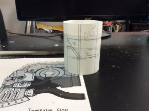
) and a fantastic head image to work off of, all you need is a cheap printer........

So with these parts gathered there should be no problem making the head and hip components.

IMG_0356.JPG

The next part is a bit of a lark on my part; you're going to need an old beach chair. We've all seen them usually tossed in the rubbish with a broken hinge mechanism but usually two or three still functioning and all we need is two.

IMG_0357.JPG

These will form working knee joints, I hope, with a bit of ingenuity.

IMG_0358.JPG

Of course it's not necessary to have flexing knees but since I have the chair I might as well go for the gusto. ;-)
 

zathros

*****SENIOR ADMINISTRATOR*****
Staff member
Administrator
Moderator
I think you should try making a difficult model, for a change of pace! Another masterpiece being born. ;)
 

Blackadder

Well-Known Member
Jaw Cut Out:

Using my vibrating saw it was a simple matter cutting out the jaw recess in the coupling.

IMG_0367.JPG

The neck is now ready for shaping and detailing.

IMG_0366.JPG

Incidentally my Chicago Electric vibrating saw is a must have tool for hobbying;

http://www.harborfreight.com/variable-speed-oscillating-multi-tool-62867.html

This cut would be really difficult with virtually any other device other than a hand tool and my $25 dollar saw was a tremendous time saver. It took about five minutes to make this cut including the blade swap.
 

Attachments

  • IMG_0360.JPG
    IMG_0360.JPG
    894.6 KB · Views: 3
  • IMG_0364.JPG
    IMG_0364.JPG
    1.2 MB · Views: 2
Last edited:

Blackadder

Well-Known Member
Snow Bound:

So to while away the weather front I did some work on the neck which I have to admit is coming out better than expected. I sheathed the coupling on 0.040 thousandths styrene to three layers and then proceeded to bevel the rear edges 45° as in the drawing.
IMG_0371.JPG

As you can see below there is quite a bit of cutting to get the 45° bevel in the front edge ............


IMG_0372.JPG


but my 'Farmers file' was up to the task.

IMG_0374.JPG

The forward bevel needs to be refined but is okay for the moment while I make the inner neck mechanism so the head can be tilted down. My previous Warlord has this capability but the mechanism is very clunky and I am hoping to refine it on this model.

IMG_0375.JPG

Finally I found this collar that will work very well in the scheme I have in mind for the side to side movement of the head and fits into the Emperor design quite well.

IMG_0373.JPG

Can anyone guess the source of this wondeous bit of sculpting?
 

Blackadder

Well-Known Member
2D vs 3D

I'm getting way ahead of myself with this head assembly so I put the brakes on to pitch an update. After scraping my initial idea of how the head assembly can tip forward on the neck I came up with this solution which will give me a lot more cockpit room for the crew. There also is a poetic license taken by the artist who drew the front and side reliefs of the Command Bridge. The huge ear discs that contain the head tilting mechanism cannot function as drawn and are of different sizes in the drawing. Never mind though, I have a solution.

I'll start with cutting the forward neck ring to allow the discs to mount flat to the sides of the neck.

IMG_0376.JPG

Carving out an outer race for the gimbal head mount pad and gluing on the gimbal bases is what is shown here. The two 0.040th inch discs are 71 MM apart and 56 MM in diameter.

IMG_0379.JPG

The bridge truss maintains the distance and keeps the gimbals square to each other and stabilizes the bases

IMG_0378.JPG

Bottom view showing the forward ring carved out to accommodate the gimbal bases.

IMG_0380.JPG

Next, the manufacture of the gimbals mounts. (The area left black in the 2D drawing.)
 

Blackadder

Well-Known Member
Gimbals:

Or Trunnions whatever, These truncated discs will support the head on the neck to allow it to look down in a purely theatrical way as a downward pointing camera would be just as effective but the menace of this skull staring down at it's victim is too good to pass up.

IMG_0381.JPG

Above; the disc is a simple truncated construct featuring two circles 45,0 and 54,0 MM separated by 2,0 MM by 4,8 MM styrene spacers.

IMG_0382.JPG

Unfortunately I got the angle wrong so I have to re-sheath the bevel but that's not a big deal.

IMG_0383.JPG

Tomorrow I hope to be working on the cockpit.
 

Blackadder

Well-Known Member
The Visor:

Allowing for the helmet I mounted the gimbals with extended visor mounts made of 0.015 thousandths sheet styrene. As I don't really have a plan for the cockpit, chin or gullet piece all this is subject to change but at least now I understand how the cheek pieces work with the gimbals.

IMG_0387.JPG

I suppose the best thing is to cut the helmet to see where it falls in relation to the ears (gimbals) and the amount of clearance required to allow the head to lower and raise.

IMG_0386.JPG

Somehow I managed to guess right which moving part eclipses which and for that I am grateful.

IMG_0385.JPG

Later on this evening I'll cut the helmet but I need to relax a bit after this thoroughly draining exercise in design. Martini Time!!!!!
 

Blackadder

Well-Known Member
Thanks for the reply,

Helmet:

My initial thought was to use a suitably shaped bottle to form the helmet but after experimentation I found that was unsatisfactory for my obsessive compulsive mindset. I opted instead for building up the helmet out of stratified layers of styrene and cutting the helmet out of the resulting block in much the same manner as I did for my Warlord Titan

IMG_0400.JPG

This also relieves me of the necessity of finding a suitable glue for mating the different sources of plastic......

IMG_0401.JPG

It's bad enough that I had already go through the identical thought processes in making my Warlord but to have not learned for my previous effort defies logic. :(
 

Blackadder

Well-Known Member
Ready To Begin Shaping:

The layering is complete and all needs be done is the shaping

IMG_0418.JPG

I made the helmet about an eighth inch over sized per inch to allow for carving and sanding

IMG_0419.JPG

Tomorrow I should be well along on the paring down to the rough dimensions.

IMG_0420.JPG
 

Blackadder

Well-Known Member
Thanks for the reply,

First and Second Contour Cuts:

Most of which are done on a stationary belt sander.

IMG_0425.JPG

One more preliminary contour cut to make.....

IMG_0424.JPG

The sides have to be rough sanded at about 45° before the finishing contour sanding.

IMG_0423.JPG
 
Top