Beroc's Warhound

[I am moving this out of my Intro thread to this forum so that it is in the right place.]

I put my Landraider project on hold for a side project that I felt was worth some attention. Since its a hobby, I can do that sort of thing. I went looking for a good printout for a Warhound Titan. (again, go big, or go home) I didn't find one that was spectacular. However, I did find a simple DIY Warhound (if you search google for that you will find the pdf) This was a basic black and white version of a Warhound. So I set out to make it. I quickly found that it was missing alot of stuff, and had zero detail. It did however, have shape.

So, I sent out to remake it into the type of titan I wanted to make. I took the bitmap plans and put them into Illustrator and went to town. The goal was to make almost every piece better in some manner. Using the stuff I learned from the previous models and Patoroch's skills. I knew I could add simple lines to just about everything and make it all fancy schmancy. I wanted more. In the plans I saw that they require some piston to be added to it. There is nothing in there about a piston. So I had to do some calculations and measuring and playing to get a cool piston. What I came up with was a big piston that actually acted like a piston. Next, I wanted the basic model to be more 3d. Not just lines added onto whatever and colorized. I added new pieces that fit the motif. I looked at many pictures of the Warhound from Games Workshop. It had quite a bit of filigree. So that was my next part. Add coolness to the model.

So enough talking. Let me give you guys some pictures with a couple of thoughts...
20140806_165846_resized.jpg
The new foot compared to the old foot.


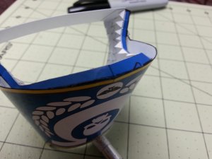
This is about my lucky piston. A simple hint is to use anything you can to make things right. You can see that I tightly wrap one part around a screwdriver and the other around an Xacto knife. With that done, Now, I glued all of my pieces in place. (except for the opening.)
20140806_095542_resized.jpg 20140806_100006_resized.jpg 20140806_100135_resized.jpg

I actually started doing this in the opposite manner. Glue the open end first and the piston end. Once dry, slide them together and seal both ends. I also found that this particular piece is about the same size as a standard hole punch. So much easier than cutting by hand.

Here is a good hint. If you ever have to glue something that is very close to another thing but don't want them to be permanently stuck together. Put some glue on an extra sheet of paper. then use your finger to transfer the glue into the place you want, lightly. Once you have the glue in place, set your piece. This is all done very carefully.

Best thing in the world.......

Elmers Craft Bond Quick Dry Glue... OMG, it is almost as good as sooper glue.
 
I was going to give this a header of "Pass the joint" I figured that the admins would frown on it.

So I got to thinking. The plans show the use of all this "non-paper" material. As this is an exercise in building my titan solely out of paper, that would not do... I thought long and hard on how I could achieve the 1" PVC on the lower and upper weapon mounts. They had to be very stout and still be functional. I saw (at some point) where a guy built an entire Warhound using paper, but it didn't look like the plans I started. He went way farther paper wise than I intend to do here. It was a very structural model and he went way beyond the 40k stuff.

http://www.librarium-online.com/forums/painting/142802-cheap-titan-you-say.html

OK, so on to some pics. (This is really a guide on how to assemble the joint)

20140807_092628_resized.jpg
So the first thing I did was to design the whole thing in 3ds max. It involved an outer holder and a lower insert. Here is the beginning of the holder. It is an outer casing, a cap, in inside casing and some corrugation material. The load of the weapon should pull against the outer casing and the glue that attaches it to the top. Since this is perhaps the greatest load here, I glued that zig zaggy thing into the cap to make it fairly solid.
20140807_092743_resized.jpg
Next, I put a cap on the inside of the upper sleeve. once completely glued, that sucker won't move. The corrugation will keep the whole upper part in place.

20140807_094043_resized.jpg
Now I am starting to work on the joint that sits inside of it.the same corrugation is applied here, but the sleeves are reversed. (it will all make sense in a bit)

20140807_102319_resized.jpg
Now, I build the other side. using the same as above. This will create a yo yo. I put the top of the second part on before I built it.


20140807_102527_resized.jpg
Glue and pressure... gotta have pressure.

20140807_101606_resized.jpg
Now, I am building the pins that hold this all in place. This small piece will be the part that you pull out to release the joint. (it will allow you to change weapons on the titan)

20140807_110728_resized.jpg
And finally the completed joint. It is very tight. The pin head is reinforced to make sure it can handle some wear of taking it in and out. I may revisit it at a later date.

Imagine that the top is glued to the shoulder and the bottom is glued to a weapon. It rotates freely though.

In the end I had to extend the holes in the back so that I didn't have to fidget with it to get it to slide in.
 

Attachments

  • 20140807_101049_resized.jpg
    20140807_101049_resized.jpg
    433.6 KB · Views: 124
Hello all again.

Today (actually yesterday) I got to work on my shin guards for my titan. The original ones followed an older titan and didn't look very impressive. So I went into max and tinkered around until I found something that was pretty cool. Printed it out and tested it... WRONG.... so I made some changes... WRONG.. then some more.... WRONG.... OMG I wasted paper on this.

So to make a long story short, I finally got the concept working and everything seemed to be working fine. As I was doing tests I realized that there wasn't any connection between the two sides, so I also included a connection between them, so that as it set, it would hold a bit better. (the first ones where very skewed) With the amount of gluing and waiting time it takes to make this, I had to add marks and tabs to help with alignment.

Pics of the process: (again, kind of an instructional about how to assemble this)

20140812_110135_resized.jpg

First, I glued the braced side for the farthest point on my sides and glued the brace together. This way, I could see the shape as I was working on it. (Do remember, that I bent all of the teeth in this and black lined it so I wouldn't be too messy later. I also wrapped the whole guard, so I got a predictable shape. To do this, I simply used the curved part of my desk and pulled it back and forth across it. This warped the paper and gave it shape.)

20140812_104916_resized.jpg
Next, I glued the next tab section into place while curving the part that goes up to it. I also glued that brace to set the shape. I then proceeded to glue the curve between them, then started on the upper section. You can see in the picture that the front teeth and parts are pushed into the model. This is so that the teeth quit grabbing the front. It is very hard to glue stuff when it is pushing against what you are trying to glue. It is important to note that the front vertical piece (the one that leads to the front) is not glued. This is so that I can maneuver the front into place for gluing. If I glued it, the next part would be next to impossible.

20140812_105420_resized.jpg
Now, I glued the front center and matched the mark for alignment. I actually only glued the first 2 teeth. This way It gets the center but I don't have to mess with trying to keep everything level at this point. 2 teeth at a time, I glue and level them until I have them all done. With the last teeth on each side, I also glue the upper piece that I did not glue earlier. (You can see excessive glue on the model. It is white glue that dries clear.) The problem I encountered on this was that the pieces were very hard to keep edge to edge. In the end, that was not hugely important. Black marker fixes anything... LOL)


20140812_110345_resized.jpg
OK, the next part is the bottom side of the guard. I glued the two ends onto the bottom teeth of the other, then glued the center mark. (4 teeth glued)

20140812_111108_resized.jpg
Next, 2-3 teeth at a time, I glued and leveled it until I reached the back part. Again, if the back part is not perfect, that is ok. we can hide it. It should be very close though.

So with all of this, now I let it sit for about 10 minutes so that the glue can become hard. The next step will start to remove the braces. I also take the time to use a marker to black line the back since now it is much sturdier than when it was all apart.

20140812_112139_resized.jpg
Now, onto the back. I warp it so that it fits into the area. and remove the upper brace. (I cut it with some scissors.) Now, I glue all the top teeth in the front and push the back plate into the braced bottom aligning the marks, top and trying to not get it hung up in the bottom teeth. When you press this, the sides should line up as well. Keep lots of pressure on this until that glue sets. (Remember, I am using quick drying white glue, so that is about 20-30 seconds. I hold it longer. (If this comes unglued for any reason, it is going to be a pain to fix.)

20140812_112342_resized.jpg
Next. making sure that the bottom teeth are all set in place, I glue about 4 of them and center the bottom mark. I now have the top and a few of the bottom in place

20140812_113429_resized.jpg

Now, I start gluing until I am an inch or so away from the bottom brace on all 4 parts. Again, I wait 10 minutes before I cut that brace so the glue has time to set. I cut the brace at an angle so that it folds correctly into the bottom part. Fold it, black line it and I glue the last of them together. At this point, I pay attention to any skewing that happens as I glue this. Try to make them straight with the rest of the model.
20140812_113718_resized.jpg
Tada... finished. You will see this on the model in later pics. When I put it on it and glued it I got a warm fuzzy feeling, then realized that I forgot to pee during all of this....
 

Attachments

  • 20140812_110333_resized.jpg
    20140812_110333_resized.jpg
    330.3 KB · Views: 115
Almost to the half way marker. This has been quite an adventure.

Let me start off with the waist joint. As per the shoulder joints, this one had to move. and even better it had to be able to be disconnected. At first, I thought it was going to be this big joint that I could mimic from the other one. Alas, that was not the case. I had about 2 inches by less than a half an inch to work with. So that ruled out the whole paper dowel I used on the other one. I could, however, use a bit of corrugation to make it a little stronger.

Some pics:

20140813_123438_resized.jpg
Like the other, I start off with a double tube and some support for it. It is supposed to hold all the weight of the titan's lower part, so I figured it needed some extra umph.

20140813_124451_resized.jpg
The upper part gets some of the same treatment. (thank god this won't be visible, it looks horrible.) Since I only have to keep it locked, then I don't need the big upper case as I had with the gun mounts.

20140813_124828_resized.jpg
Now, you can see the final pieces. They fit into each other and slide. If you look closely at the marks, you have to turn the top around to get it to unlock.


Now onto some pics of some finished stuff:

20140812_113829_resized.jpg
This was one of the pics I wanted to post before, but I ran into too many pictures on the post. It shows a pair of scissors holding my link for a piston. Never be afraid to use anything to help you build. Scissors are great tools, now one more use for them. ;)

20140812_114021_resized.jpg
OK, this was also supposed to be in the last post. It is the finished guard on a leg.... Yes, you peed just a little too. :D

20140812_172300_resized.jpg
What is better than one... TWO... Not only two, but two and the cod piece.

20140813_164545_resized.jpg
I am about out of time today, but I can't just leave it this way. I won't have time to upload the pic of it all together, but here are all the pieces almost assembled.

(with a shameless plug for Mnt Dew....)
 
And here I am again... final time for the week.

So I got to tinkering with the body components. Sadly, they just won't do. So I decided to start recreating them from scratch. This and a couple of really good pics of what this thing is supposed to be like. I figure I can do some pretty cool stuff.

Below are the first images of what it should be like. I don't know yet if I am going to redo the guns or not, I know for sure that they are going to be colored correctly though. I tried desperately to not include the sarcophagus from the movie The Chronicles of Riddick. OMG that would make this. But it really wont go with it.

Y.jpg Z.jpg x.jpg
Til next week.

This is all done in 3ds Max 3.1. It is nothing but a screen capture for what is on my screen. No lighting, no nothing. I will take these and move them into Pepakura, then into Illustrator and "fix" them so that they work correctly.
 

ARMORMAN

FOUNDATION CORNERSTONE
I like what I'm seeing...I've done a reaver from the DIY templates (some pics are around here somewhere) and know how you feel about the lack of detail. I look forward to the finished project.
 
Teaser time.


Since I can't actually build today or tomorrow, I can work in 3d and illustrator and get things moving towards the final goal. I took all my 3d models and worked them through unfolding and put them into illustrator. I also started doing the decoration on it and other pieces. I really only have gotten started with this part. It will take quite a bit of work.

Attached is a "teaser" of what the overall illustrator file works out to be. 20 pages thus far, and probably a good 10 more in weapons.

teaser.jpg
 

zathros

*****SENIOR ADMINISTRATOR*****
Staff member
Administrator
Moderator
3DS Max, eh? I'm impressed, not because you said you use it, but because of the results you get with it. Great stuff here! You have our attention, and I would love to see the ship that they used to get to Crematoria, the , you know, that little really excellent one, made into a model, Flattery C-19 Short Range Skiff , (Hint, Hint!!) . You have been here such a short time and have really wowed "us"! :)

riddick+merc+ship+miniature.jpg
 
Finally got time to take pics of some progress.


These are the images that are actually going with the docs. Rather than point and number and waste time I don't really have right now. I will just post some pics of what each page makes.

20140820_090436_resized.jpg
Main Hull
20140820_090641_resized.jpg
Back Cap with upper door
20140820_103127_resized.jpg
Two inner shoulder pads with lower door. There is also the spacer that helps support the weapons.
20140820_094004_resized.jpg
One trick I used was to puncture the inner pad in 4 places to show where the spacer should go.
20140820_125219_resized.jpg
Shoulder pad. The trim is actually located on the previous page from this one as this is a big piece for each page.
20140820_140214_resized.jpg
In pad assembly, the first thing I did was to glue only one part of the two together, using the spacer and anything else I could to get it in the correct place. (From trying to build the original with an inner pad, this was incredibly difficult. This is actually where the inner spacer came from because it was way too hard to get them to glue and hold them without it moving all over the place.)
20140820_172805_resized.jpg
Back Shoulder pad.
20140821_104002_resized.jpg
Lower jaw and cabin cover.
20140821_114716_resized.jpg
Collar, neck and "hat"
20140821_115038_resized.jpg
This is simply the hat placed on the cabin cover.

What wont be in this is the fact that I had to create a lip to hold the cabin cover onto the jaw.

And yes, because of the 10 picture limit, I am going to make you wait til next week to see the body assembled.
 

mysteroid

Active Member
Fantastic work! Love the progress pictures, gives a great impression of your creative process. Good idea fuel!

Steve
 
Thank you guys for the comments.

Up next are the final pics from last week.

20140821_133708_resized.jpg
These are the parts from the cockpit page. I took the time to make them all since nothing was referenced in the original document.

20140821_134207_resized.jpg
Totally Assembled cockpit.

20140821_134309_resized.jpg
How to insert the cockpit.

20140821_134533_resized.jpg
Final jaw piece with the cockpit inserted and glued.

20140821_144258_resized.jpg20140821_144246_resized.jpg
20140821_144234_resized.jpg20140821_144210_resized.jpg
20140821_144157_resized.jpg

Hopefully tomorrow, I will have some pics of the guns for it. :D
 

zathros

*****SENIOR ADMINISTRATOR*****
Staff member
Administrator
Moderator
I must say your building skill is quite impressive also. Straight lines, all plumb and square like that is not easy to do. Great stuff! :)
 
SOOOO CLOSE.....

Lets start off with the guns I did finish today...

20140827_171820_resized.jpg
Inferno Cannon.... Unfortunately the big tank on the bottom had to go. It was hitting the leg.

20140826_092039_resized.jpg
Alignment picture.... In order to get the tubes to line up, you have to put one on, them glue the whole assembly together so that you get a good placement. This way it doesn't have gaps where you don't want them.

20140827_122547_resized.jpg
Plasma Bastion. Complete with purple laser effect. (aww come on, it took me seconds to make that effect)

20140827_122436_resized.jpg
A needed picture for the final file... This is the part on top of the Plasma Bastion. It didn't fit with the rest of the gun on the page.


Now to the gun that isn't quite done and may be the bane of my existence at the moment.
20140827_171639_resized.jpg
The Mars Pattern Turbo Laser is the last piece for this. I hate having to redo plans just because things aren't going straight. The cans on the outside of the barrel, I initially made as one piece that the gun glued to.... Oh no... no way, that wasn't straight in the slightest. So I changed it and made the cans fit over the barrel.

Looking at it, that yellow thing looks like a pencil. but it is a laser site. I am going to have to show a pic of it after I cut it down. It is supposed to fit onto the gun mount.

Tomorrow is the end... I will prep the file and get it out here and on another thread so it can be a public, no-cost model like everything else.
 

zathros

*****SENIOR ADMINISTRATOR*****
Staff member
Administrator
Moderator
You gift is a most honorable one, and we, the whole forum, I can safely say, are most appreciative of it. :)
 
FINALLY!!!!

OK, this is not the last post on this I am going to do. Mostly cause I have to take beauty shots of the whole model and post thousands of pics of it.

Lets get started with the last gun.

20140828_074323_resized.jpg
When you build it, you should build it like this..... Getting the whole thing to line up and the castle to look right on the barrels would be a pain. It is better to assemble it on the barrel and slide the castle over it.

20140828_080617_resized.jpg20140828_080704_resized.jpg
As promised.... This is the laser site. It needs to be sawed in half. (mostly) and attached to the mount. I provided a couple of reference lines for this.

20140828_093752_resized.jpg
Mars Pattern Turbo Laser.

As an overall, this project was fun. I learned a whole lot about how to build the templates to make these out of. I don't know if this is my last model, but I am certainly proud of it.

Thank you all for your comments.
 
Last edited:

Revell-Fan

Co-Administrator
Staff member
Administrator
Moderator
This is awesome! Thank you very, very much for this special gift! I'd love to see some pictures of the completed model. :)
 
Top