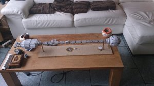
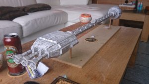
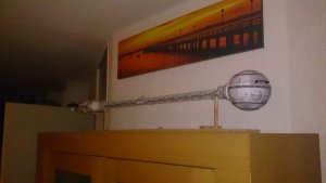
I stamped my foot down at life and demanded some time for the Discovery..... I got my way ...

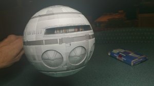
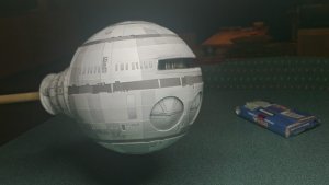
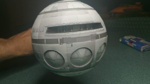
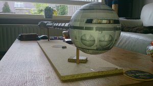
I eventually got the window sub-assembly attached to the upper sphere........ Damn, what a nightmare that was..

It took me most of yesterday evening to get the thing fitted correctly. If it was out of position by the slightest fraction, it effected the whole sphere in shape or one way or another.
I figured the best way would be to attach the two side frames first.... It took at least 5 attempts...... :sour:
I used the beermat jig to accurately align the top and bottom edges.
It was one hell of a fiddly job, with various curses included. :shamefullyembarrased:
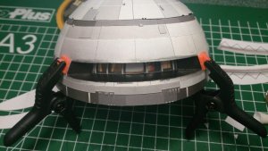
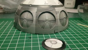
The texturing around the window is a little lacking in comparison to the studio model and I wanted to add that with raised detail. Also a handy way to help cover up some colour bleed above the window.

I used a spare copy of the relevant part and marked and then cut out a random pattern of slots....
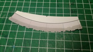
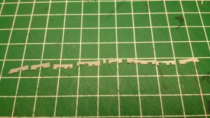
I made a set for above and below the window and then glued them on ....... I see that some of them are a little wonky, but I'll rectify that later on final touch-ups.
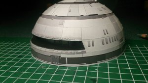
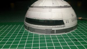
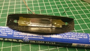
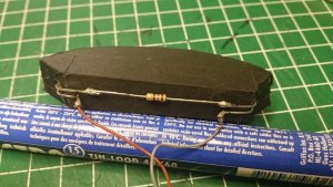
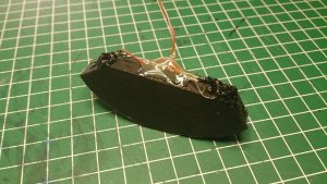
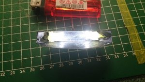
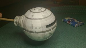
I also fitted the top cap of the upper sphere and apart from final touch-ups, fitting of the light box, and detailing of the centre darker band, (which I will do after marrying the two halves of the sphere,) that pretty much completes construction of the two halves. All that is next to do, is join the two halves together, which, I hope, I will get done this evening at some point.
On pre-planning for the next critical part of the build, the joining of the sphere to the neck, I devised a way of keeping everything round, perpendicular and square to its relation.
UHU02 provides a 2 piece ring assembly to aid in attachment of the sphere. This ring must fit perfectly to the edge of the joining flange without any waviness, it must be perfectly round, the edge flat and must be kept perpendicular to the flange.
Mmmm, I don't have enough fingers for that, so, JIG Time!

By placing the neck assembly with the joining flange downwards on a smooth surface, if you lightly press down on the spine coupling, it naturally splays out the joining flange to its maximum and uniform circumference. I then measured the diameter of the flange at 10,4 cm on my model.
NOTE: The lengths of the provided ring pieces are too long and need to be trimmed and adjusted to perfectly fit the joining flange. Knowing the diameter of the joining flange, calculating the circumference, and therefore the (close to) strip length of 32,7 cm was simple. It makes a good starting point anyway.
So, I cut out a 10,4 cm diameter ring from thick card. I used a compass cutter for this. (
@zathros Did you ever make yours ?

)
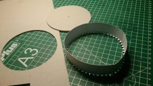
I then persuaded the thick card ring into the support ring. As it turned out, the thickness of the blade of the cutter compensated for the thickness of the paper of the support ring.

I wasn't worried about any waviness on the back of the support ring, only the joint face was important..

Then, on a flat surface, I pushed the ring assembly into the cut out hole of the thick card.....
A perfect gluing jig..


I lightly glued up the tabs and the inside of the joining flange and placed this accurately into position over the jig and pressed down as before, (as when measuring, to splay the flange,) and let the glue tack up a bit.
Before the glue dried too much, (because the jig is cardboard ...

,) I removed the jig by pushing downwards gently, away from the join. I left the inner ring in its place and it wont be removed either.
Then, using something suitable to apply pressure in the correct places, in this case, a coffee pad tin did the job, I added a little weight, locked the cat out of the room and left it to dry for the evening.
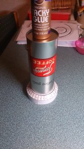
We'll see if that works out.........


See you all soon, if all goes well ......


 Well, I had never doubted that you would not have the balls to do it.
  Awesome! thumbsup


