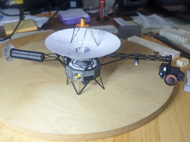
NASA Voyager 1/48 John Jogerst
- Thread starter Tesco4
- Start date
You are using an out of date browser. It may not display this or other websites correctly.
You should upgrade or use an alternative browser.
You should upgrade or use an alternative browser.
Instrument Assembly:
Finally it's time to put some of these pieces together.
Firstly a slight heart in mouth moment when I realised that the smaller greebled lens cover on the imaging camera had gone missing. The 1.5mm one. Miraculously I found it on the floor, undamaged!
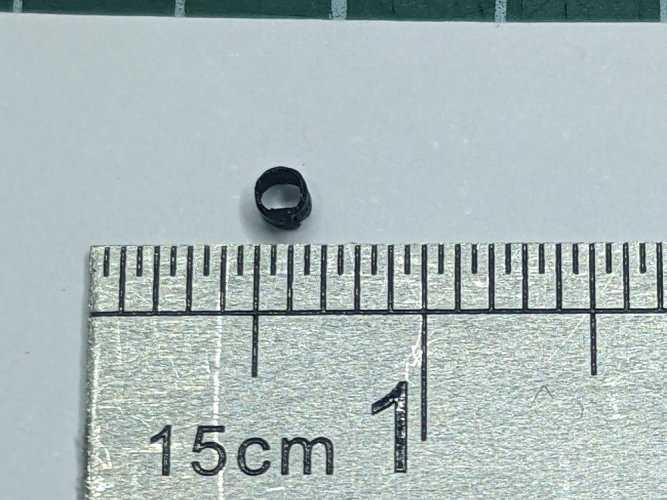
So once that was glued back on, I mounted most of the instruments on the instrument truss and mounted the truss onto the main bus, including the extra reinforcing arm support which is definitely needed to keep it roughly horizontal. In most cases I started with some PVA glue so I had a bit of time to check orientation in more than one plane, make sure they were vertical or horizontal, not too far back or forward on the truss and the vertical column, and once they'd dried I went round reinforcing the joints with a little CA glue on the end of a needle, especially where something flat was glued to something round.
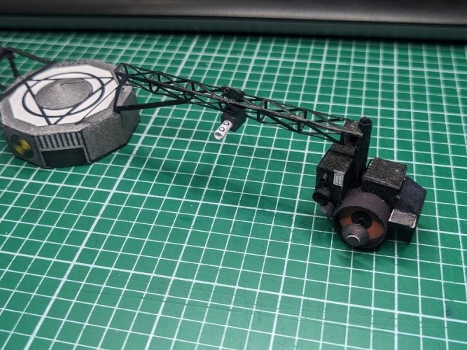
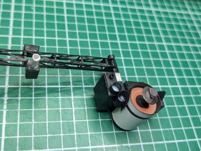
I think they've all come out pretty well. Nice to start to see it coming together, rather than just a bunch of separate parts.
More instrument additions and further progress tomorrow.
Finally it's time to put some of these pieces together.
Firstly a slight heart in mouth moment when I realised that the smaller greebled lens cover on the imaging camera had gone missing. The 1.5mm one. Miraculously I found it on the floor, undamaged!

So once that was glued back on, I mounted most of the instruments on the instrument truss and mounted the truss onto the main bus, including the extra reinforcing arm support which is definitely needed to keep it roughly horizontal. In most cases I started with some PVA glue so I had a bit of time to check orientation in more than one plane, make sure they were vertical or horizontal, not too far back or forward on the truss and the vertical column, and once they'd dried I went round reinforcing the joints with a little CA glue on the end of a needle, especially where something flat was glued to something round.


I think they've all come out pretty well. Nice to start to see it coming together, rather than just a bunch of separate parts.
More instrument additions and further progress tomorrow.
tiny parts falling down on the floor or just vanishing from the table. That happens to me on a regular basisInstrument Assembly:
Finally it's time to put some of these pieces together.
Firstly a slight heart in mouth moment when I realised that the smaller greebled lens cover on the imaging camera had gone missing. The 1.5mm one. Miraculously I found it on the floor, undamaged!
View attachment 223886
So once that was glued back on, I mounted most of the instruments on the instrument truss and mounted the truss onto the main bus, including the extra reinforcing arm support which is definitely needed to keep it roughly horizontal. In most cases I started with some PVA glue so I had a bit of time to check orientation in more than one plane, make sure they were vertical or horizontal, not too far back or forward on the truss and the vertical column, and once they'd dried I went round reinforcing the joints with a little CA glue on the end of a needle, especially where something flat was glued to something round.
View attachment 223887View attachment 223888
I think they've all come out pretty well. Nice to start to see it coming together, rather than just a bunch of separate parts.
More instrument additions and further progress tomorrow.
The floor monster has ate many of my detail parts.tiny parts falling down on the floor or just vanishing from the table. That happens to me on a regular basis
Mine ate several original Kenner Star Wars weapons. I hope it dies the most painful death.
This is really coming together nicely. I too have lost many small pieces to the "ether". I know the feeling and frustration all too well.
Hmmm, I reckon there's a student somewhere who may pick up on this phenomenon and theorise perhaps a planet inhabited by our missing pieces, a la Veet Voojagig in HHGTTG about the missing biros and the biro planet!
I couldn't say it better but maybe they will...Hmmm, I reckon there's a student somewhere who may pick up on this phenomenon and theorise perhaps a planet inhabited by our missing pieces, a la Veet Voojagig in HHGTTG about the missing biros and the biro planet!
O never mind I found my missing piece.
there are over 2200 triangles to UHU02's tower.. my hands and eyes still hurt from it. but my god does it look beautiful.. min stands 3 feet tallI feel your pain!
When I built the under-construction ring of UHU02s 2001 ASO Station V, (twice!), it was literally; Blood, Sweat & Tears!
Your truss turned out great!
Next up for both of us....UHU02s Tokyo Tower!!
https://www.zealot.com/threads/uhu02-tokyo-tower.179143/
Think I'll stick to the 240 for the Magnetometer Truss on this model for now. Hats off to you and Dan and anyone else who has the patience for the Tokyo Tower!there are over 2200 triangles to UHU02's tower.. my hands and eyes still hurt from it. but my god does it look beautiful.. min stands 3 feet tall
most of them weren't too bad.. its the 1/16 to 1/8 sizes that it got bad.. yes that small..hahahah.. as the great doctor once said. (Oh, the pain, the pain...) hahahaThink I'll stick to the 240 for the Magnetometer Truss on this model for now. Hats off to you and Dan and anyone else who has the patience for the Tokyo Tower!
Well that "tomorrow" turned out to be nearly 2 weeks! Life got in the way.
So here's a catch up with some progress made since.
More Instruments added:
First the two Star Trackers, complete with UV glue "lenses" - they orient the spacecraft in relation to the star Canopus. Why Canopus and not Sirius, the brightest star in the sky - because the angle between the Sun and Sirius is very small, whereas Canopus has a much larger angle away from the Sun, making it easier to achieve guidance and navigation.
Also attached now is the Plasma/Wave antenna mount (blurred in the pic below) the little box inside the RTG truss. It requires holes for the antennae wire to pass through, I put a little bit of CA glue on the surface, which stiffened it up and made it easier to drill the very small holes ready for the wire at the end.
I found it's worth gluing pieces these into place now rather than once the HGA dish has been glued on as the instructions state, it will get in the way.
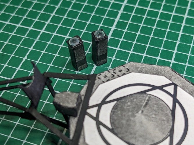
Added the little Plasma instrument onto the instrument truss.
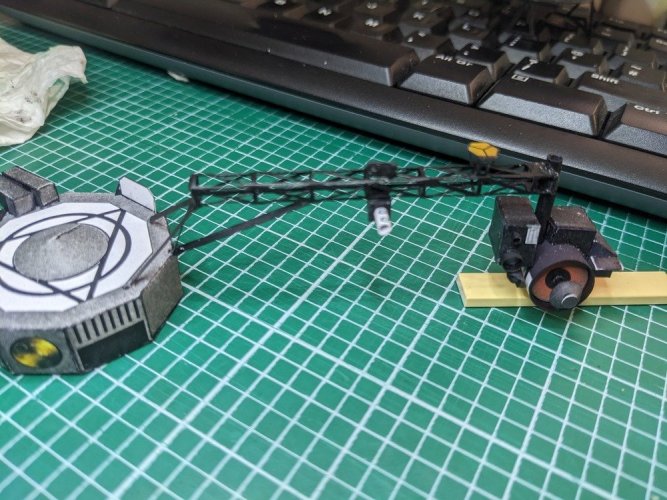
Main assembly:
Now we're doing major assembly, the bottom fuel tank addition was glued onto the bottom of the main bus with the booster attachment truss, all CA reinforced for strength after bending to roughly the right angle. I had to flatten the points at the base of the truss which is more in keeping with the actual spacecraft where it sat on top of the booster motor.
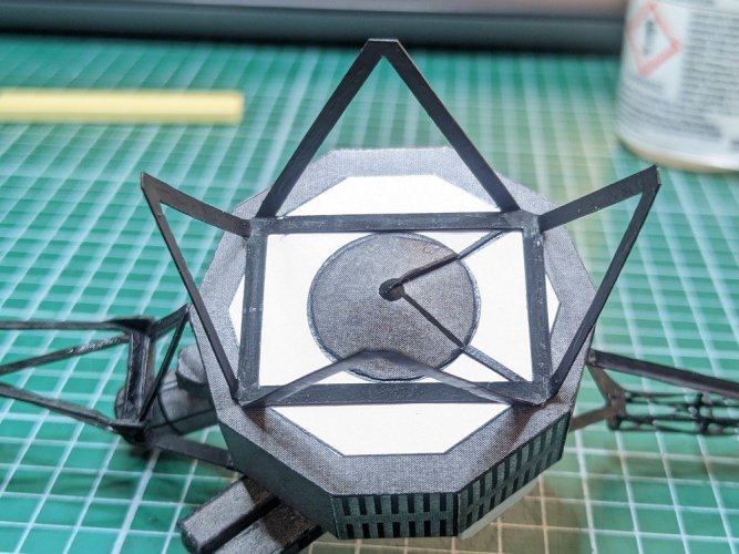
The Magnetometer canister is glued into place. I decided not to bother with the optional holder for it, just to use the folded up flap from the truss. And the little end piece on the other side.
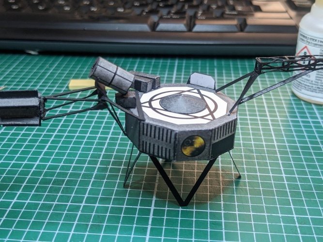
Then the HGA array is glued in position on top of the main bus.
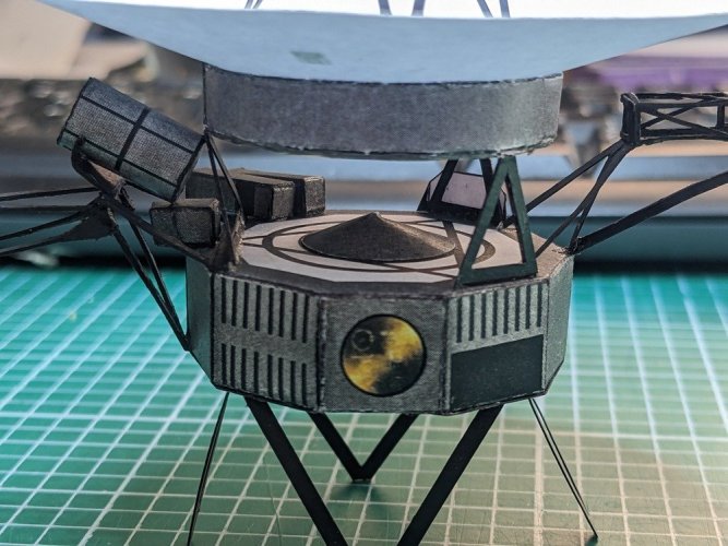
And we're nearly there.
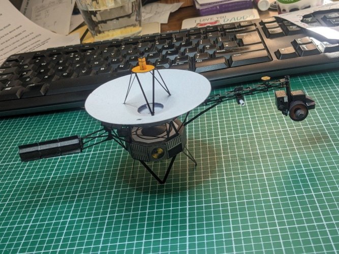
Outstanding items: 2 wires for the Plasma/Wave antennae, the Magnetometer boom arm and the calibration panel/shunt radiator.
So here's a catch up with some progress made since.
More Instruments added:
First the two Star Trackers, complete with UV glue "lenses" - they orient the spacecraft in relation to the star Canopus. Why Canopus and not Sirius, the brightest star in the sky - because the angle between the Sun and Sirius is very small, whereas Canopus has a much larger angle away from the Sun, making it easier to achieve guidance and navigation.
Also attached now is the Plasma/Wave antenna mount (blurred in the pic below) the little box inside the RTG truss. It requires holes for the antennae wire to pass through, I put a little bit of CA glue on the surface, which stiffened it up and made it easier to drill the very small holes ready for the wire at the end.
I found it's worth gluing pieces these into place now rather than once the HGA dish has been glued on as the instructions state, it will get in the way.

Added the little Plasma instrument onto the instrument truss.

Main assembly:
Now we're doing major assembly, the bottom fuel tank addition was glued onto the bottom of the main bus with the booster attachment truss, all CA reinforced for strength after bending to roughly the right angle. I had to flatten the points at the base of the truss which is more in keeping with the actual spacecraft where it sat on top of the booster motor.

The Magnetometer canister is glued into place. I decided not to bother with the optional holder for it, just to use the folded up flap from the truss. And the little end piece on the other side.

Then the HGA array is glued in position on top of the main bus.

And we're nearly there.

Outstanding items: 2 wires for the Plasma/Wave antennae, the Magnetometer boom arm and the calibration panel/shunt radiator.
Last edited:
You are doing a really great job those parts are looking stunning.
All looks so crisp, clear and clean.
All looks so crisp, clear and clean.
So, nearly there. But wait ... I feel the need for a little more greebling ...
Greebling 3: RTG enhancements
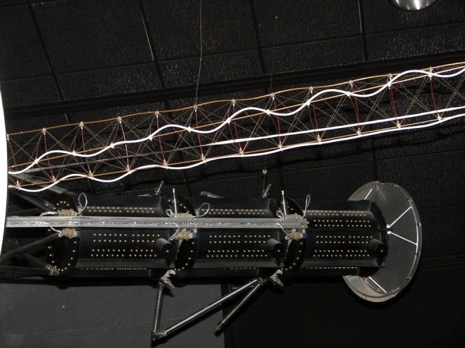
At the end of the RTG is that silver structure, I guess it's a protective shield or something. That looks doable
Cut some parts out (including a few strips in case I decided to attempt those legs as well).
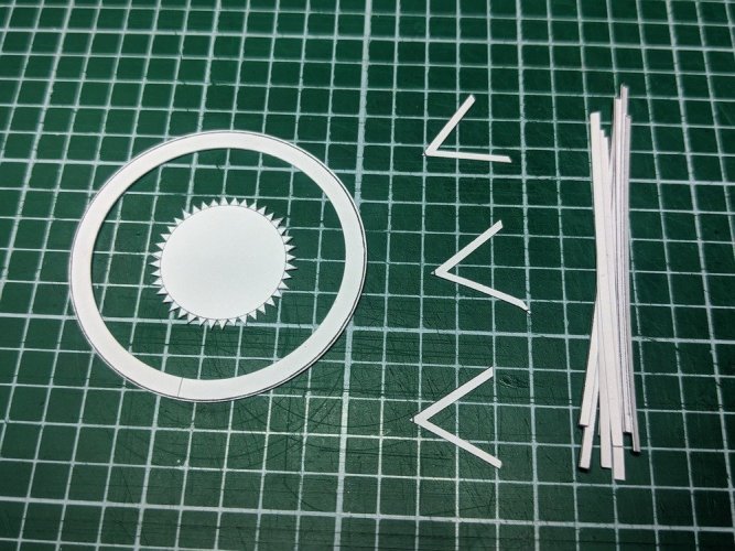
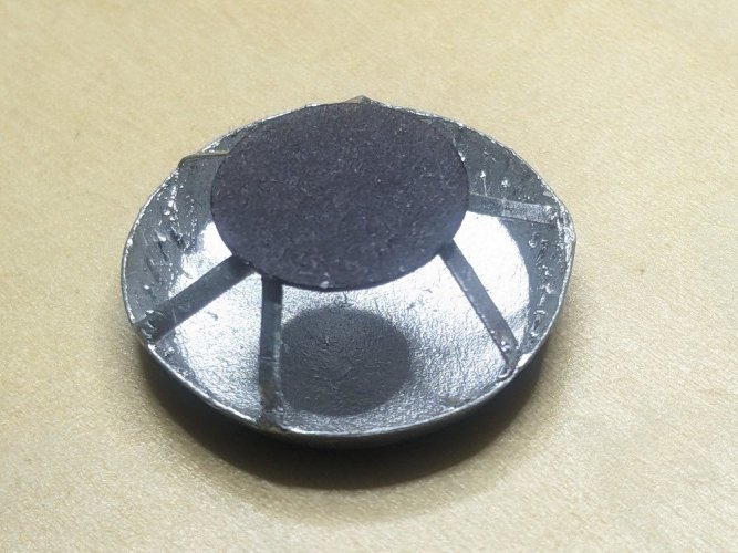
A bit of trigonometry to figure out the inner radius needed to create the conical section round the flat end plate, and some struts. Here's partial assembly with a bit of bending in on the struts to glue onto the end of the RTG. All three struts folded in. The a quick layer of CA on the inside edges.
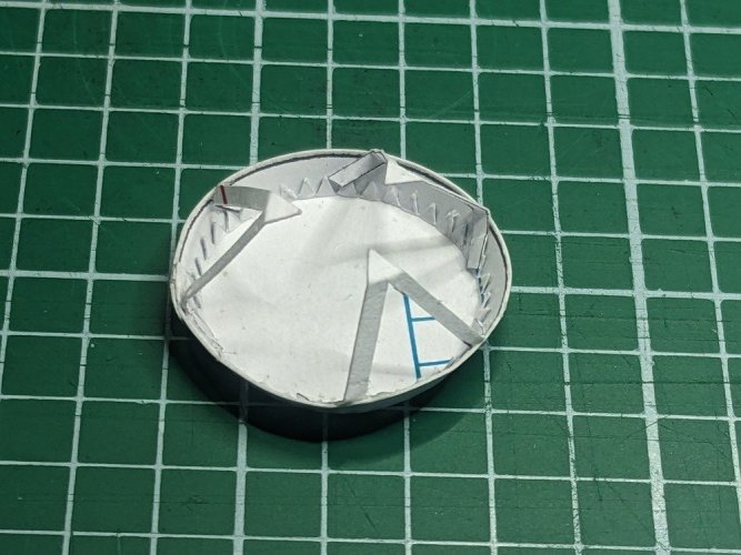
Then the whole thing gets a coat of silver paint.
I used a gloss silver enamel Humbrol paint I had from plastic kit modelling, which gave a really good uniform coverage on the inside and struts as you can see in the picture below, but on the outside I couldn't get it to spread uniformly flat with a brush, the brushstrokes stayed making it look a bit amateur, so after a couple of tries I resorted to a polished aluminium spray can, couple of coats and it's all looking ok.
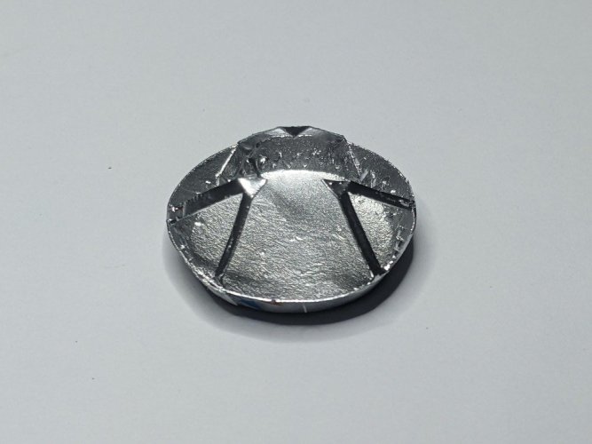
Gluing it onto the RTG was a challenge - the main difficulty being I'm trying to glue a piece onto the main structure while getting it aligned in all 3 dimensions at once so that it's central to the RTG and the end plate is as close to 90º as I can make it. After three aborted attempts I rethought it.
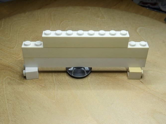
I can't do it all at once. I need a way of splitting up the task, separating gluing it centrally to the RTG from also making it accurately perpendicular. So I cut out a circle and thought if I can put a bit of weight on top I can get the struts parallel to that circle, and then glue the circle to the RTG. So a bit of improvisation with Lego again, spotted some glue on the ends of the 3 legs, put the circle on top, then added the Lego on top of that to force the black circle to be parallel to the end plate itself. Also once the Lego was holding it down, I had a bit of time to be able to adjust the position of the circle to be as central to the end plate as possible.
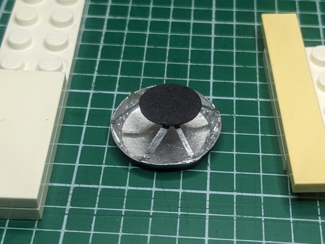
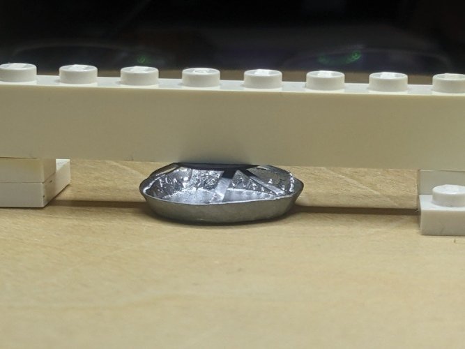
Then it was simply a matter of gluing this to the RTG which was a lot easier to try and get it on centrally.
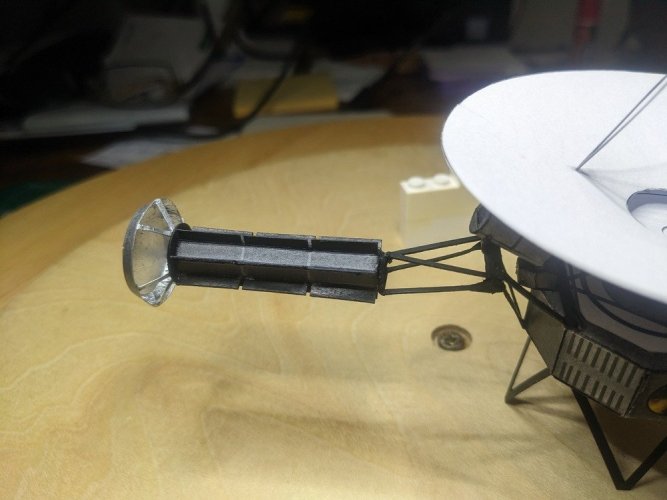
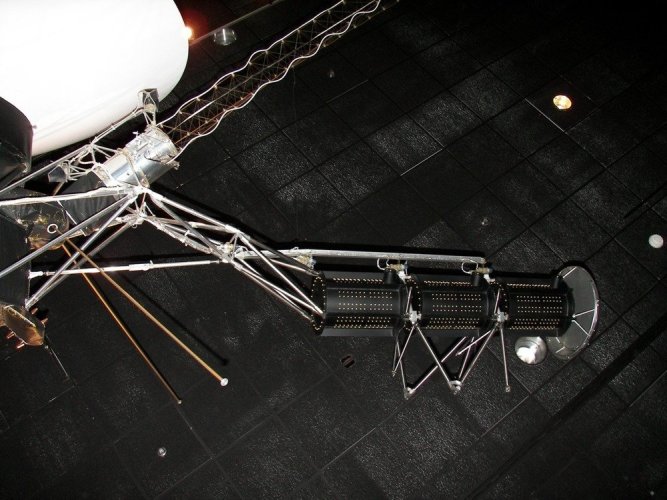
I have had my eye on those extra silver metal legs (where the RTG attached to the spacecraft before deployment where it hinged outwards) and the truss carrying cables across the top, and I would then think I have to make the whole of that RTG truss silver along with the MAG canister and who knows where this might end! But I need to find a finish line for this model soon, so for now I'll leave these extra opportunities. I might come back to them after I've made a few different models.
Greebling 3: RTG enhancements
At the end of the RTG is that silver structure, I guess it's a protective shield or something. That looks doable

Cut some parts out (including a few strips in case I decided to attempt those legs as well).

A bit of trigonometry to figure out the inner radius needed to create the conical section round the flat end plate, and some struts. Here's partial assembly with a bit of bending in on the struts to glue onto the end of the RTG. All three struts folded in. The a quick layer of CA on the inside edges.

Then the whole thing gets a coat of silver paint.
I used a gloss silver enamel Humbrol paint I had from plastic kit modelling, which gave a really good uniform coverage on the inside and struts as you can see in the picture below, but on the outside I couldn't get it to spread uniformly flat with a brush, the brushstrokes stayed making it look a bit amateur, so after a couple of tries I resorted to a polished aluminium spray can, couple of coats and it's all looking ok.

Gluing it onto the RTG was a challenge - the main difficulty being I'm trying to glue a piece onto the main structure while getting it aligned in all 3 dimensions at once so that it's central to the RTG and the end plate is as close to 90º as I can make it. After three aborted attempts I rethought it.
I can't do it all at once. I need a way of splitting up the task, separating gluing it centrally to the RTG from also making it accurately perpendicular. So I cut out a circle and thought if I can put a bit of weight on top I can get the struts parallel to that circle, and then glue the circle to the RTG. So a bit of improvisation with Lego again, spotted some glue on the ends of the 3 legs, put the circle on top, then added the Lego on top of that to force the black circle to be parallel to the end plate itself. Also once the Lego was holding it down, I had a bit of time to be able to adjust the position of the circle to be as central to the end plate as possible.


Then it was simply a matter of gluing this to the RTG which was a lot easier to try and get it on centrally.

I have had my eye on those extra silver metal legs (where the RTG attached to the spacecraft before deployment where it hinged outwards) and the truss carrying cables across the top, and I would then think I have to make the whole of that RTG truss silver along with the MAG canister and who knows where this might end! But I need to find a finish line for this model soon, so for now I'll leave these extra opportunities. I might come back to them after I've made a few different models.

Through doing this model I've learned that it's sometimes not easy to work out exactly what things looked like for designing a model, particularly this far back (1970s). A lot of internet photos are of test versions or of the "spare" one they built which wasn't used, and sometimes parts are covered up (like that imaging camera or the booster truss legs) and don't represent what actually went into space. There are also a lot of diagrams and illustrations, some of them photorealistic, but they're only representations and not true to life. Some of the best images for checking were the NASA photos of the assembled spacecraft during the encapsulation process where it was put into the launch housing. Even there, lots of the camera assembly looks to be covered in gold thermal blankets and you wonder if that's what actually flew, and it wouldn't necessarily make a great model.
Instrument calibration panel/shunt radiator:
This small piece should be plain on the outside (in order to have a flat blank surface for the cameras to calibrate against), and the ribs are on the inside as shown in a picture at this webpage (https://arstechnica.com/space/2024/...memory-knocked-nasas-aging-voyager-1-offline/). The photos in the model pdf have the ribs facing out but they should be inwards.
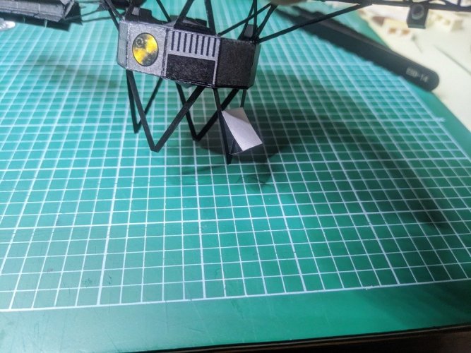
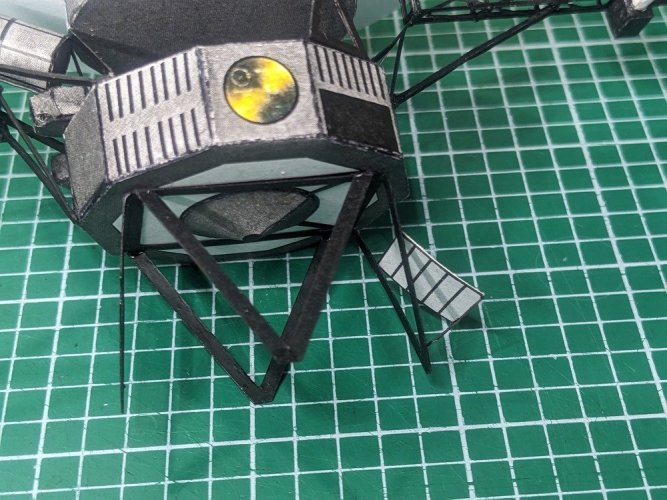
This small piece should be plain on the outside (in order to have a flat blank surface for the cameras to calibrate against), and the ribs are on the inside as shown in a picture at this webpage (https://arstechnica.com/space/2024/...memory-knocked-nasas-aging-voyager-1-offline/). The photos in the model pdf have the ribs facing out but they should be inwards.


Plasma Wave instrument antennae:
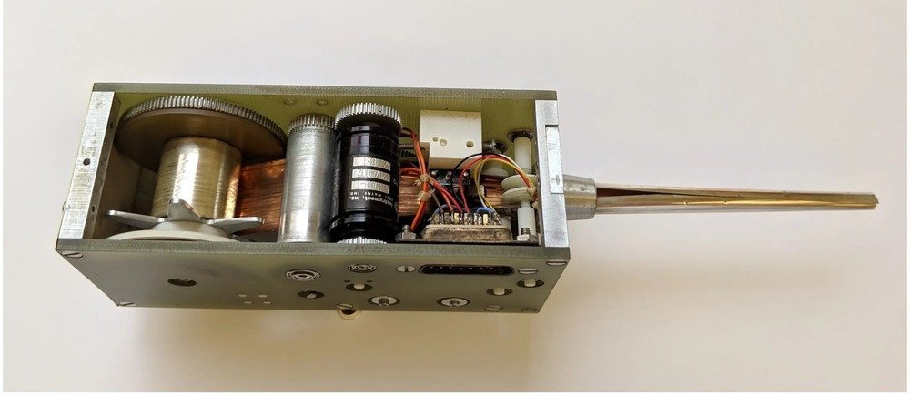
These were 10m long. Here's an amazing article shows how they got 10m antennae to extend after deployment. First they form a hollow tube from a long narrow sheet of beryllium copper, and then they unfolded it back into a long thin rectangle, rolled it onto a spool (to the left in the image below) and then deployment once Voyager was on its way was achieved by literally unrolling it from the spool, forming it back into the hollow tube as it exits the machine (to the right in the image below), a bit like the MAG boom unfurling - incredible! Of course with no gravity to distort it, it created a very long and effective antenna. They used this method on quite a few satellites around the same period. https://hackaday.com/2020/12/31/sti...hese-years-the-voyager-plasma-wave-subsystem/
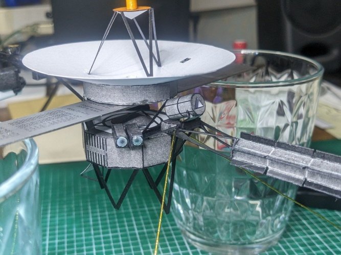
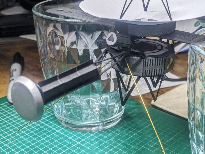
I found some gold-wrapped wire (from wife's baking supplies!) which look ok. I worried about getting the 90º angle right, but once pushed to the back of the opposite side inside the holes in the part, they sort of fell naturally to the right angle - a clever piece of design by Mr. Jogerst. Getting glue to where the enter the box is best achieved by putting a blob onto the hole, and a blob on the end of the wire so that when you push the wire in, some of it goes in (hopefully enough to secure it inside) and some stays around the hole. With everything being quite delicate (this model only weights about 5 grams), and with these wires as well, which I don't want to catch and accidentally bend), it's a bit of a faff working out how to hold the model until I've got a stand. This configuration seems to work ok for now. Once in, I think another blob of CA glue around the hole will be added to help the antennae stay in position.
These were 10m long. Here's an amazing article shows how they got 10m antennae to extend after deployment. First they form a hollow tube from a long narrow sheet of beryllium copper, and then they unfolded it back into a long thin rectangle, rolled it onto a spool (to the left in the image below) and then deployment once Voyager was on its way was achieved by literally unrolling it from the spool, forming it back into the hollow tube as it exits the machine (to the right in the image below), a bit like the MAG boom unfurling - incredible! Of course with no gravity to distort it, it created a very long and effective antenna. They used this method on quite a few satellites around the same period. https://hackaday.com/2020/12/31/sti...hese-years-the-voyager-plasma-wave-subsystem/

I found some gold-wrapped wire (from wife's baking supplies!) which look ok. I worried about getting the 90º angle right, but once pushed to the back of the opposite side inside the holes in the part, they sort of fell naturally to the right angle - a clever piece of design by Mr. Jogerst. Getting glue to where the enter the box is best achieved by putting a blob onto the hole, and a blob on the end of the wire so that when you push the wire in, some of it goes in (hopefully enough to secure it inside) and some stays around the hole. With everything being quite delicate (this model only weights about 5 grams), and with these wires as well, which I don't want to catch and accidentally bend), it's a bit of a faff working out how to hold the model until I've got a stand. This configuration seems to work ok for now. Once in, I think another blob of CA glue around the hole will be added to help the antennae stay in position.


