Successful Use of Electromagnets?

BigJim

Member
Nov 19, 2006
154
0
16
76
North Plains, Oregon
dixiemtn.com
Gary,

You are right about the AMP turns. The difference is I think you are not seeing the "flux-focus" when you pick up a piece of steel since it is wider than the gap. Try the same test picking up a small screw or ball bearing that is less than the gap.
 

Torpedo

Member
Jan 20, 2007
278
0
16
79
BigJim said:
Back in the 60's when I was an electronic tech we called that TMS (Tune for Maximum Smoke). Very small adjustments were known as RCH. Won't share the full meaning but R = red:) .

Royal, where I worked. :thumb:
 

Torpedo

Member
Jan 20, 2007
278
0
16
79
BigJim said:
Gary,

If you don't have one I would recommend you (and everyone else) get an angle head grinder. I see harborfreight.com has a cheapo 4.5" one on sale for $9.99.:thumb: Might not be the quality you want for daily use but should be OK for the odd job. Haven't tried recently but with most of their tools you could get a two or three year replacement warranty for a few bucks. Wait - you are into model trains - money must not be an issue - get the Porter Cable one. Only $129.00.:)
It just so happens that I own both of those. That is, I have a rather pricey Porter Cable and an el cheapo from HF (may not be the exact same model as the $9.99). You can tell the difference.:eek: tooth1 The HF model definately has a higher "cringe" factor (as in wince when you hear the gear noise), but I haven't been able to kill either one yet.
 

Gary S.

Senior Member
Oct 13, 2005
1,576
0
36
Texas
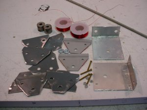
BigJim, I agree that the distance between the sidepaltes may make a difference, but not sure how to test it. I made two test tracks out of some blue foam as seen it the previous photos. I put the single coil unit in one and the double coil in the other, and then ran some cars over them to see what the couplers did. Both set-ups worked the same as far as I could tell, the couplers moved plenty and uncoupled just fine. I think that either set-up is viable.

The double coil will be able to stay on longer with less fear of overheating, but at a higher monetary cost. Since I already have 5 of these built, I guess I will stick with them.

Another VERY IMPORTANT note: These magnets will also cause cars weighted with steel to move around. Even steel truck screws and the metal draft box lids on Athearn cars can be made to move if they have free-rolling trucks. Now, awhile back I also found that the permanent under-the-ties Kadee #308 can do the same thing. I took all the steel out of 90% of my rolling stock already, replacing it with lead weights or pennies, and I use brass screws for the trucks and draft box lids. On the Athearn blue boxes kits, I have been working on removing the stock draft boxes and adding Kadee draft boxes.
 

BigJim

Member
Nov 19, 2006
154
0
16
76
North Plains, Oregon
dixiemtn.com
I have killed one of each - Porter cable was fixed under warranty.

The important thing is how much it will "turn" the coupler. I would try putting a piece of plastic or foam, about the same thickness as the distance from the top of the electromagnet to a coupler and use a a track nail or other small "rod' of steel. Hold it at an angle with you fingers and see how much it wants to turn perpendicular when you pulse the coils. Not very precise but you may be able to feel a difference with the different gap widths.

The other way to test (slaps head) might be to set a car over the magnet and turn up the voltage until it opens the coupler.

P.S. Don't know "ROYAL". Hints?

Perhaps you need a "Flux Capacitor". No wait that is used for time travel. (Back to the future)

As far as I know maintaining a magnetic field does not require any energy. Otherwise your regular magnets wouldn't work. All of the VA goes to heat in a DC electromagnet. Having twice the turns makes the two coil twice as efficient. The best would be a single coil with twice the turns or bending the side plates to have the gap match the width of the coupler arms.
 

Gary S.

Senior Member
Oct 13, 2005
1,576
0
36
Texas
BigJim said:
As far as I know maintaining a magnetic field does not require any energy. Otherwise your regular magnets wouldn't work. All of the VA goes to heat in a DC electromagnet. Having twice the turns makes the two coil twice as efficient. The best would be a single coil with twice the turns or bending the side plates to have the gap match the width of the coupler arms.

I agree that with DC applied to the electromagnet, the wattage is going up in heat.... with a couple of exceptions.

As you state, no energy is required to maintain the field. But it is going to take energy to establish the field. The inductance of the coil comes into play when we first energize the coil and the flux lines are expanding out from the magnet and cutting across the other turns of the coil. When the magnet is turned off, the collapsing magnetic field and the inductance will produce a counter voltage... which is why a transistor that is controlling a relay coil can be destroyed if the coil doesn't have a "kickback" diode in parallel.

Also, I would think that the current through the coil would change anytime a ferrous material comes into contact with the field. It changes the shape of the field, and this change would be felt in the inductance of the coil. Using the law of conservation of energy, if we can make a piece of metal move, it will certainly require an input of energy, more than just is being used to heat up the coil wires.

All of this is speculation based on my rudimentary knowledge is is subject ot correction.
 

BigJim

Member
Nov 19, 2006
154
0
16
76
North Plains, Oregon
dixiemtn.com
OK into theory now.

Inductor does store energy. (I guess it is a flux capacitor). Energy needs a time factor.
Watt-seconds? The amount of energy stored in the inductor is based on the inductance and the voltage. I would have to look it up but I know 1 Henery is a very large inductor and you would need something close to that to store many watt seconds. Since your coil the coil charges very quickly (It works changing 120 times a second) there are not many watt seconds stored. Doesn't matter much as this energy is converted back to heat when the field is shut down.

Once the field is established the current flow (energy) generated in a wire moving through a magnetic field comes from the energy required to move the wire - not energy taken from the coil. Otherwise a DC can motor could not act a a generator when you turn the shaft. and two magnets wouldn't repulse/attract.

All in all the stored energy stored (and released) is very small compared to the static resistive disapation.
 

Gary S.

Senior Member
Oct 13, 2005
1,576
0
36
Texas
BigJim said:
Once the field is established the current flow (energy) generated in a wire moving through a magnetic field comes from the energy required to move the wire - not energy taken from the coil.

I see what you mean and never even looked at it that way. Very astute observation! But I am still not sure about what happens when an electromagnet causes a piece of metal to be moved towards it. Time for an internet search I suppose.
 

BigJim

Member
Nov 19, 2006
154
0
16
76
North Plains, Oregon
dixiemtn.com
A Watt-second is a joule. I think we are talking micro-joules to move a small piece of metal. Also the motion is only the conversion of the potential enengy caused by the magnetic field being converted to kenetic energy as the metal "falls" toward the magnet and converted back to heat when it stops.

Consider your test area as a closed system. You add energy in the form of electric current (power supply) to the system. Push the button for five seconds. 5 sec x 12 volts x 1.5 AMPS = 90 joules. After five seconds nothing is still moving (kenetic energy), no significant electro magnetic radiation (light, radio, etc.) left the area and you haven't lifted anything to a new higher position (potential energy) so the only choice left is 90 joules of heat added to the system.
 

Gary S.

Senior Member
Oct 13, 2005
1,576
0
36
Texas
I've decided to just go with the double coil arrangement at 24 volts. It is strong, doesn't draw too many amps, it doesn't get all that hot even when left on for awhile, and I've already got 24 volt relays for the one-shot circuit. Plus, I've already purchased enough coils to double up what I need.

Hopefully I will get time to put some of these into my benchwork and get some track laid so I can play around with the system on the layout instead of just testing it on the workbench. I am confident it will work well.

Thanks for all the food for thought. I like all the theoretical stuff and "how does that work?" is built into my brain.
 

Gary S.

Senior Member
Oct 13, 2005
1,576
0
36
Texas
For those who had asked about a tutorial for these uncouplers, here are a few things:

1. Probably the easiest thing to do is to buy the O scale uncoupler which is around #11-$12. These come with 2 coils and double sideplates, and should work just fine with HO scale, built as the directions show. You can wire the coils in series and operate at 24 volts, or put them in parallel and you can operate them at 12 volts up to 16 volts. With the 24 volt series arrangement, the current will be between 1.25 to 1.5 amps. With the parallel arrangement and the lower voltage, the current will be doubled.

2. You can add some extra home-made metal sideplates to help focus the magnetic field even more. I made mine out of some thin sheetmetal. I cut the shapes with tin snips and then drilled holes in the appropriate spots. I'll post some pics.

3. My layout is 2.5 inches thick... .25" of cork roadbed, 2" of foam, and another .25" plywood on the bottom. I devised some simple mounting brackets to mount the magnet to the layout. I used thin aluminum plates and bent a 90 degree angle for a mounting foot. Drilled holes for attaching to the magnet bolt and for screws to attach to the layout. Will post some pics.

4. On my particulat uncouplers, I mixed the O scale uncouplers with some HO scale couplers I already had. I'll also post pics of what I did with that.
 

Gary S.

Senior Member
Oct 13, 2005
1,576
0
36
Texas
Here are the parts I used, with some close-ups of the home-made sideplates and the aluminum mounting brackets. I used aluminum for the mounting brackets because it is non-magnetic. I was afraid that using a steel bracket would spread the flux lines out instead of having them concentrated through the sideplates to the area at the track.
 

Attachments

  • MVC-014S.JPG
    MVC-014S.JPG
    38.7 KB · Views: 82
  • MVC-015S.JPG
    MVC-015S.JPG
    37 KB · Views: 83
  • MVC-016S.JPG
    MVC-016S.JPG
    38.2 KB · Views: 82

Gary S.

Senior Member
Oct 13, 2005
1,576
0
36
Texas
Again, I will mention it is probably best to just use the O scale uncouplers as they are. You can discard some of the plastic mounting pieces that come with it though. The O scale coupler is strong enough to just be mounted under the ties. If you can devise a mounting system, you don't have to put all the plastic mounting pieces above the track that is shown in the instructions.

With my magnets, I first shaped the home-made steel plates to match the factory sideplates. Once they were cut out and drilled, I bolted them to the factory sideplate and then squeezed them with pliers to match the contour. Do this for each home-made sideplate.

The reason for the extra sideplates is to give more metal to focus the flux lines up to the track where you need them.
 

Attachments

  • MVC-014S.JPG
    MVC-014S.JPG
    39.3 KB · Views: 81
  • MVC-015S.JPG
    MVC-015S.JPG
    37.4 KB · Views: 77

Gary S.

Senior Member
Oct 13, 2005
1,576
0
36
Texas
This particular magnet, I have added 3 extra plates to each side. Here is what one side looks like.
 

Attachments

  • MVC-016S.JPG
    MVC-016S.JPG
    38.4 KB · Views: 75