RR Xing signals

Pitchwife

Dreamer
Apr 23, 2001
1,728
0
36
71
The middle of nowhere Oregon
Visit site
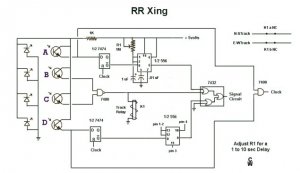
A few months ago N Gauger wrote in another thread, http://www.the-gauge.com/forums/showthread.php?s=&threadid=5754&highlight=detector that he would like a grade crossing detector that would work like the prototype. I have been working on this project for a special application on my own for awhile and have come up with the following schematic. The components are relitivly inexpensive. The most difficult aspect I have come up with yet is the placement and concealment of the sensors. In this diagram I am using light activated sensors. There are additional control features that my project requires that wouldn't be needed on most layouts.

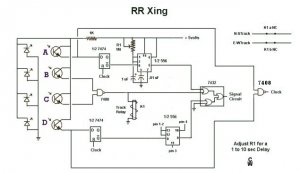
Sensors B & C would be placed on either side of the crossing, while A & D would pe placed where you would want the crossing signals to detect the oncoming train.

Theoretically the signals would activate when the aproaching train activated the first detector and would shut off as soon as the last car cleared the crossong.

I say theoretically because I have yet to build a prototype to determin the validity of my idea. If anyone is really interested in it I could probably find some time to breadboard it and test it's viability.
 

Attachments

  • rr xing j1.jpg
    rr xing j1.jpg
    29.1 KB · Views: 331

scoobyloven

Member
Jan 13, 2002
308
0
16
zeeland michigan
Visit site
pitchwife

here is one i did for my layout i use it to show where my trains are at and it can also be used to run a grade crossing and all the parts can be bought from radio shack
 

Attachments

  • 01 train.jpg
    01 train.jpg
    44.4 KB · Views: 320

Pitchwife

Dreamer
Apr 23, 2001
1,728
0
36
71
The middle of nowhere Oregon
Visit site
Hi Scoobyloven. I am familiar with that circuit and it is fine to use if you need to know if a particular piece of track is occupied. The problem with using it at a grade crossing is that if you put it far enough up the track to give the crossing enough warning to clear, it shuts off as soon as the last car of the train goes by while the middle of the train is still occupying the crossing. If you put it closer so that the signals are turned off as the last of the train passes, the crossing doesn't have enough of a warning. Neither one is prototypical.

What I was striving for was a circuit where the crossing signals would have advanced warning, AND shut off as the last car went by, like a prototypical crossing would. Also, it needs to work in both directions.

BTW, all of the components in my circuit are also available at Radio Shack.
 

ezdays

Out AZ way
Feb 3, 2003
6,339
0
36
Arizona
bigbluetrains.com
I am more familar with logic circuits than with crossing signals, but it seems to me you only need two sensors, A and D. When either A or D sensed a train, the relay would actuate and stay that way until both A and B sensed nothing. This assumes that the train is longer than the distance between A and B. What is the function of B and C in your circuit?

Is not what you want to drop the crossing gates and turn on a red signal light? If so, that can easily be done, with or without a delay timer, but I see no need for the timer.

Let me know and I'll draw up a circuit for you.

Don
 

Ray Marinaccio

Active Member
Aug 4, 2003
1,940
0
36
66
Dewey Az.
Visit site
I built a two IR sensor system with a timer for the crossing flashers and gates on my old HO layout. the timer was used due to the slow trains I was running. The only problem I had was due to the small dia. of my loop, if I was running a long train, by the time the last car cleared the sensor and the timer reset the other sensor was about to be tripped again.
The next one I build will have an adjustable timer.
 

Pitchwife

Dreamer
Apr 23, 2001
1,728
0
36
71
The middle of nowhere Oregon
Visit site
When I started out devising this circuit it seemed like it would be a simple thing. It rapidly turned into a complex logic nightmare. :confused:

A and D are the remote sensors that detect an approching train. B and C are sensors at the crossing that detect the absence of the train.

When A or D are activated the signals start and do not shut off until both B and C are at a low state after the train passes.

This works with any length of train coming from either direction. At least I hope that it does. :)

If only A and D were used the signals would not shut off until the end of the train was as far away from the crossing as the earliest advanced warning sounded rather than just after the last car passed.
 

Pitchwife

Dreamer
Apr 23, 2001
1,728
0
36
71
The middle of nowhere Oregon
Visit site
ezdays, the timer is to keep the signals running until the train gets to the crossings and B and C activate to run the signals until the train is clear.

Ray, the problem with using a timer is just as you found out, It works fine as long as you only run a certain length of train at a certain speed. Otherwise the signals shut down too early or too late. Using an adjustable timer is fine, but you have to adjust it manually for each individual train. I was striving to eliminate that problem. If this circuit works like I think it will, it will work with any length of train going at any speed.
 

Ray Marinaccio

Active Member
Aug 4, 2003
1,940
0
36
66
Dewey Az.
Visit site
I do like the idea of not adjusting the timer for each train. I also like the signals canceling after the last car clears the crossing.
I haven't worked with logic circuits in a long time. I'm probably missing something looking at the scematic, What keeps the Other outer sensor from retriggering the signals?
 

Pitchwife

Dreamer
Apr 23, 2001
1,728
0
36
71
The middle of nowhere Oregon
Visit site
An excelent question Ray. As I had designed this circuit a year or so ago I had to go back over the logic to figure it out.
The answer is the clock pulse. Until both A and D are high again (meaning no traffic obstructing either one) the clock remains low and will not allow any change in the D Flip-Flops. If you are using two tracks, you will need a seperate circuit for each one.
 

penngg1

New Member
Sep 8, 2003
36
0
6
Newfield, NY
Visit site
May an obsolete engineer (sons statement) break in here. you will have to translate this into solid state components.

Sensors A&B are wired for "or" condition and output goes to an off delay timer. This masks the signal break between cars.
the output from the timer operates the gates and powers the alternating flashing lights.

I hope I didn't muddy the waters. Good luck.
Bud
 

Pitchwife

Dreamer
Apr 23, 2001
1,728
0
36
71
The middle of nowhere Oregon
Visit site
Hi penngg1. Glad for all of the input I get here. I'm no profesional engineer but have worked with electronics most of my life and have learned to "borrow" other schematics and piece together enough to get it to do what I want. :D

I'll try to go through the logic as best I can. With no train, the sensors ABC&D are all at an ON or HIGH state. The sensors should be mounted at an angle to the track to eliminate false blips between cars. When a train crosses sensor A it changes the output to a LOW and sends that to the D FlipFlop and the NAND gate (just realized I put an AND gate there instead. See revised diagram attached) to go HIGH sending a clock pulse to the D FlipFlops. This allows the output of the D FlipFlop to go HIGH and give a triggering pulse to the timer which activates and holds the signals on until the train reaches sensor B (thus the timer).
Then
B and C, which are placed at the crossing, hold the signals on by driving the output of the NAND gate HIGH. Once both B & C have been cleared they resume their HIGH state causing the NAND gate output to go LOW and shut off the signals. Since the D FlipFlop attached to sensor D can't operate without another clock pulse, the presence of the train has no effect on it.
Once the train clears sensor D the clock output goes back to LOW, setting up the circuit for the next train.
If a train comes from the other direction it works the same, just in the reverse order.

That's the theory anyway. :D
 

Pitchwife

Dreamer
Apr 23, 2001
1,728
0
36
71
The middle of nowhere Oregon
Visit site
I don't clame to know it all, and have fried more than my share of electronic componants
Man, I hear that. I've found that if you have access to enough sources of basic circuits and have a little knowledge of what does what, you can usually come up with a solution.

This one was a real bear though. When I started it it seemed like a simple thing to do, but as I got into it more and more it turned into a real chalenge. I'm still not 100% sure it will work. I need to breadboard it to make the final test. When I do I'll keep my fingers crossed when I power it up. :)
 

scoobyloven

Member
Jan 13, 2002
308
0
16
zeeland michigan
Visit site
pitchwife

look on the net for a electronic program tester.

i have one from when i was in school and i can make electronics for all kinds of things and test them on the pc screen to see if it would work befor i go to the work bench. it saves me alot of time and money when doing it it is better to see it work on the screen than to build it and it goes up in smoke
 

Pitchwife

Dreamer
Apr 23, 2001
1,728
0
36
71
The middle of nowhere Oregon
Visit site
scoobyloven, that was an excelent piece of advise. I hadn't even thought of such a program, but a few tries on the old search engine brought up one that I think will work very well. Thanks for the tip! :) :)

Now as soon as I learn how to run the thing I'll let you know how well it works out.

Thanks again. :):)
 
Originally posted by Pitchwife
well scoobyloven, I still think that your recomendation was a good one. Unfortunatly the program I got had too steep of a learning curve. :confused: So back to smoking ICs. Thanks anyway.

Besides, its a lot more fun to breadboard and make it work than building virtual models that may work onscreen but not in real life. Heat up that soldering iron!!
 

Pitchwife

Dreamer
Apr 23, 2001
1,728
0
36
71
The middle of nowhere Oregon
Visit site
OK, the simplest solution I came up with is one that is similar to a driveway sensor I designed many years ago.

The train passes Sensor 1 which activates a latching relay K2 and sets the polarity of the loops as well as the direction of the two turnouts. When the train completes the loop and comes from the other direction it activates Sensor 2 which turns on a timed circuit that opens a NormalClosed relay and opens the trigger circuit of Sensor 1 thus disabling it. After the train passes both Sensors 1 and 2, the timer times out, enableing Sensor 1 again. When the train passes Sensor 1 the third time it unlatches the relay K2 reversing the polarity of the loops and the turnouts. With each odd numbered sucessive pass of Sensor 1 the loops are switched from CW to CCW.

This is entirely seperate from the sensors on the loops (L1 and L2) that switch K1 on and off reversing the polarity of the mainline. Since the polarity of the mainline is determined by the sensors in the loops it is always in phase with the loop polarity.
 

Attachments

  • directional loops g.jpg
    directional loops g.jpg
    24.6 KB · Views: 60
Neat circuit! Fun stuff designing these logic systems that depend partly on train movement as well as electron movement. Even more fun when you can see them actually work!

Was looking back at your RR crossing circuit, one thing you might want to consider (and simulation may or may not catch this) is the setup time of the Dflop. Different logic families have different timing requirements, the 7474 needs 20 nanosecond setup time and 5nsec hold according to the data sheet. The LS, S, F, HC etc versions of this device are all different timings. These little billionths of a second timing details (aka race conditions) can make or break a circuit that is logically correct but real world dependent. Many engineers have been caught pants-down by this sort of thing.

If the clock NAND is the typical 10 nsec propagation delay, the rising clock pulse arrives at the Dflop 10 nsec after the D input falls, but should be at least 20nsec after the D falling edge to meet the Dflop setup requirement and guarantee correct operation. Adding some delay (chain of gates, or short RC delay with a Schmidt trigger NAND instead) to the clock will ensure plenty of setup time. Or use a 74F74 with only 3 nsec setup time required but keep the slow 7400 or 74LS00 NAND with a fastest prop delay of 1/2 typical.

BTW, all these timing parameters are in the data sheets for these devices, www.digikey.com has most of the data sheets online for easy reference rather than wading through a manufacturer's website for the same info.