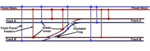
I've taken your diagram and redrawn it to show the two rails. The top rail of each track has been coloured red and the bottom rail has been coloured blue. At the top, I've added your track power buss - ie the two wires that will feed the rails. These are also coloured red and blue to correspond to the two colours of the rails.
Wherever you see a round blob, either a red one or a blue one, that's where your track feeders are soldered either to the rail or to the track power buss.
Notice that for the two tracks, Track A and Track B, that are to the left of the turnouts, you have two pairs of feeders. Also, for the two tracks, Track A and Track B, that are to the right of the turnouts, you have two pairs of feeders.
And, in the part between the two turnouts, we have one pair of feeders. You will not get a short because you have an insulated frog on your turnouts.
Now, what are track feeds, you ask? These are simply pairs of wires, one to the top rail and one to the bottom rail that will get the electricity to your tracks. You should install track feeds about every 3 feet or so to make sure there's lots of electricity getting to the tracks.
And what is a track power buss, you ask? It's simply two wires, in this case, one blue wire and one red wire, which is run from the Rail A and Rail B connections of your command station (if you use a Digitrax command station).
That's all you need to feed power to these rails. Simple, eh?
I would suggest that you might want to visit my website to get a better understanding of how to wire your layout. From the index page, click on DCC.
Bob M.