Hello Companions,
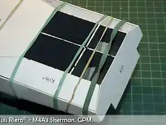
Well, I am here with another update on the Sherman. I have finished the pieces that I think are the exhaust pipes. Please tell me if I am wrong.
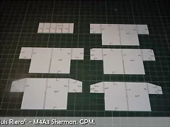
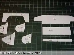
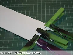
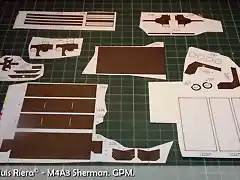
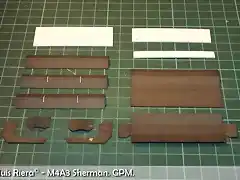
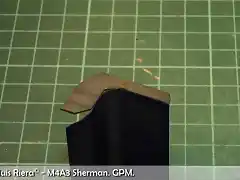
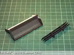
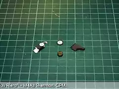
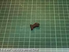
In Photo 32 I show to you the parts that compose these pieces. The one on the left, cut and the one on the right, with some manipulations to give it form.
032.
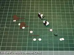
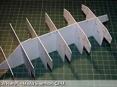
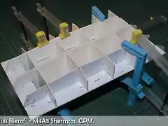
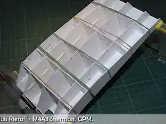
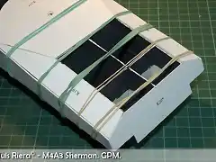
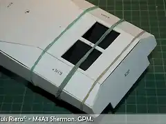
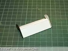
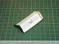
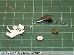
In Photo 33 I begin the process of assembly of one of the pieces. Although it is not apparent (you will see it better in Photo 36) I have stuck a small cardboard rectangle to give body to the union, because it is edge against edge. The one that I have been able to stick edge against edge without problems in the piece on the right, that appears on the great head of a needle. In Photo 34 you can see how, on the left, the squared piece is sticking, in center I am sticking discs of cardboard and their ring and on the right, the piece that simulates the exhaust. Here is sticking the part that has double curvature. And in Photo 35 one of the pieces already finished.
033.
034.
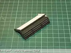
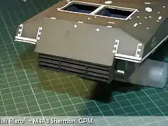
035.
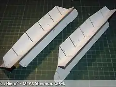
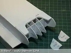
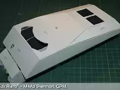
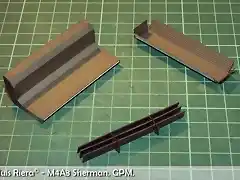
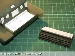
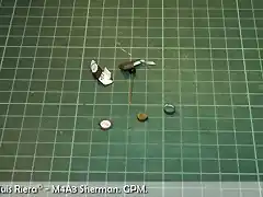
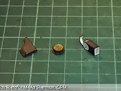
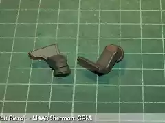
And next I show to you the elaboration of the other piece, this time with greater aproximation. As I commented to you, in the part on the left of Photo 36, you can see the cardboard piece that I have stuck to the piece 27c to facilitate the union. In the while, I am sticking the edge of the piece and the discs and the ring of the piece on the right. In Photo 37 I am finishing sticking the piece on the left, I am sticking discs to its support and the squared piece on the right is almost finished. Finally, in Photo 38 you can see the two finished pieces.
036.
037.
038.
That is everything until the moment.
Greetings.


 003.
003.
 004.
004.
 006.
006.