LED switch indicators

vdegrazia

New Member
Jan 3, 2006
38
0
6
82
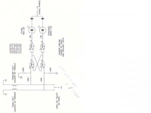
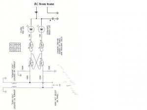
I built a circuit board using a 4001 IC ( flip/flop) to light a red or green LED to indicate which mode the switch is in. It works OK but the LED's flicker when the train is running. I am O gauge with post war Lionel. I operate the switches off of a Post war Lionel ZW trans former. All 4 of the transformer power take offs work with a common ground. I think that is the problem. The circuit I used was off of one posted on this Forum.

Any thoughts?
 

vdegrazia

New Member
Jan 3, 2006
38
0
6
82
Jim: If I knew how to post the schematic I would . In any case the flow is as follows: From the switch operating coil and panel power, the circuit goes to a 100K resistor to the 4001 IC ( there is also another 100k resistor between the first 100k resisitor and ground) to a 10K resistor to the LED to a diode to panel power.
This circuit is dublicated for each of the 2 LEDs. I hope this makes sense.

Thanks Vic
 

ezdays

Out AZ way
Feb 3, 2003
6,339
0
36
Arizona
bigbluetrains.com
Vic,

You are using DC as the power source aren't you??? Do you know what the voltage is? A 4001 IC doesn't like too much over around 20 VDC. It it's getting warm or hot, you're running too high a voltage. The flickering indicates that the source voltage isn't consistant, it's possibly being loaded down when you have a train running, or in other words, it's not regulated too well. Trains don't care, electronics do.

I'd advise getting a separate DC source for the electronics. If you're using a cheap DC supply, then you may need to add a large capacitor across the output to filter the "noise" or "ac component" from it.

There is a tutorial on DC power packs right here that might give you a better insight as to what I'm talking about.
 

vdegrazia

New Member
Jan 3, 2006
38
0
6
82
Don/Jim Thanks for the response. I am using Lionel AC power supply. As you stated. I am sure the voltage is varing while the train is running. I have yet to try a seperate power supply.
I think I have uploaded the schematic.

Thanks Vic
 

Attachments

  • LED Schematic.psd.jpg
    LED Schematic.psd.jpg
    27.4 KB · Views: 197

ezdays

Out AZ way
Feb 3, 2003
6,339
0
36
Arizona
bigbluetrains.com
Vic,

Yeah, you got it uploaded.:thumb: And yes, it is a classic 4001 flip/flop. The problem isn't in the circuit, but in your power source. If you have a meter, check the DC voltage source while the train isn't running and again while it is. You should have a clean, regulated source to run most any electronics like this.

Keep us posted.
 

vdegrazia

New Member
Jan 3, 2006
38
0
6
82
Cid: Thanks for the info. I do have two diodes, one for each LED. I will try adding the cap. per your suggest. Should I add one to each LED?

Vic
 

ezdays

Out AZ way
Feb 3, 2003
6,339
0
36
Arizona
bigbluetrains.com
Your AC is being half-wave rectified by the diodes. Incidentally, you don't need those diodes in series with the LEDs, the LEDs are diodes in themselves. Your flickering is coming from the AC source. And yes, you could add a capacitor to filter it, your best bet is to use a decent DC source. What are you using to power the 4001 IC?
 
Hi v,:wave:
If you have 2 diodes, you'll need 2 caps. Like Don says, you probably don't need both
diodes, but I think using at least one helps protect the LEDs from seeing as much of the
reverse voltage as without them. There are other ways to do this, such as a bridge, and
Don's suggestion of using separate DC supplies for your electronics is a good one. I'm just
tryin' to get you by cheap!:D :D And it wont hurt to try it :)

Don's question about the Vcc is also somethin I'm wondering about.:confused: :confused:
 

vdegrazia

New Member
Jan 3, 2006
38
0
6
82
Thanks guys. I am using the same AC source to power the IC's as I am to power the switches. I am running Lionel post war O gauge which runs on AC. I could add a DC power supply for the IC and switches but that will add more to my already wiring mess. I will try to add the caps. and see what happens.
If I were to add a full wave recitfier to between the diodes and the panel power, will that eliminate the problem?

Thanks again.
 

Thoroughbreed

Member
Aug 4, 2006
400
0
16
54
South Eastern AL
kf4jqd said:
In my digital electronics class, a loooooooooong time ago. You want to isolate AC from the digital electronics. I would use a 7805 voltage regulator for the flip flop power source. Also add a .01 microfarad capasitor to the input of the 7805 to ground.

Andy
Yeah thats what i thinking, but couldn't find the words....:D Thought you wanna uncouple ac from a digital circuit, but couldn't remember how, Figured on the rectifier, but with the ac not having constant current, ya won't have a regulated voltage required by digital circuits. The power for v+ for the chip has to be regulated. Thats part of the equation thats missing from the schematic. The ground shown in the schematic is the same ground used for the control chip? If you have 2 seperate power supplies for these circuits, now you have 2 seperate grounds. There will be a conflict as there will be varying voltages accross ground.:D
 
You can tire the grounds together. Keep the +5vdc isolated!!! You can also use an electrolic capasitor on the out of the regulator! Remember that the regulator must have a dc input too. A bridge rectifier would be great if you use an ac power source. I NEVER use the train throttles acc port as my power source. I use a regulated power supply. An Astron 20amp at 13.8vdc. It makes connecting dc accorissies up very easy! Plus it takes the strain off the throttle control.

Andy
 

pgandw

Active Member
Jul 9, 2005
1,002
0
36
kf4jqd said:
You can tire the grounds together. Keep the +5vdc isolated!!! You can also use an electrolic capasitor on the out of the regulator! Remember that the regulator must have a dc input too. A bridge rectifier would be great if you use an ac power source. I NEVER use the train throttles acc port as my power source. I use a regulated power supply. An Astron 20amp at 13.8vdc. It makes connecting dc accorissies up very easy! Plus it takes the strain off the throttle control.
Andy

Much more available these days is an old PC power supply. Plenty of both 12V and 5V regulated DC.

my thoughts, your choices