

Has anyone created a circuit to make an LED flash? I have been trying to make multivibrator circuits work but all they want to do is stay on constantly. I havent tried using ceramic capacitors instead of Electrolytic. could this be my problem?
LED Flasher troubles
- Thread starter b28_82
- Start date
You are using an out of date browser. It may not display this or other websites correctly.
You should upgrade or use an alternative browser.
You should upgrade or use an alternative browser.
555 Timer circuits?
Short version:
http://wolfstone.halloweenhost.com/TechBase/com555_555TimerCalc.html
Everything you wanted to know about 555's but were afraid to ask
http://www.talkingelectronics.com/FreeProjects/555/555-P1.html
I think I've always uesd multy layer ceramics.
Short version:
http://wolfstone.halloweenhost.com/TechBase/com555_555TimerCalc.html
Everything you wanted to know about 555's but were afraid to ask
http://www.talkingelectronics.com/FreeProjects/555/555-P1.html
I think I've always uesd multy layer ceramics.
It could be the electrolytic if your timer was set for longer cycles. Even if you were using a 555 (great choice for this application), we would use low-leakage capacitors if we weren't too fussy about the accuracy, but tanelum capacitors if we got over 1 or 2 mfd. Electrolytics have high leakage resistance which acts like a voltage divider in any R-C circuit preventing it from ever fully charging or fully discharging. The larger the capacitor value, the smaller the leakage resistance.

There are two sites that my Son and I use
http://www.kpsec.freeuk.com/index.htm
look under Projects for a simple flasher
We used this circuit for two flashing LEDs
He even used this as an experiment to show how different resistors make the led flash at different rates for the local school fare. Try changing the 39K resisters.
http://www.uoguelph.ca/~antoon/circ/flash2.htm
DWP
F
Fred_M
Just buy a flashing LED (has built in circuit) such as at http://www.allelectronics.com/cgi-bin/category.cgi?category=340200&type=store or Radioshack even.
This site has lots of electronic train circuits that work. http://home.cogeco.ca/~rpaisley4/CircuitIndex.html#index FRED
This site has lots of electronic train circuits that work. http://home.cogeco.ca/~rpaisley4/CircuitIndex.html#index FRED
Originally posted by ezdays
It could be the electrolytic if your timer was set for longer cycles. Even if you were using a 555 (great choice for this application), we would use low-leakage capacitors if we weren't too fussy about the accuracy, but tanelum capacitors if we got over 1 or 2 mfd. Electrolytics have high leakage resistance which acts like a voltage divider in any R-C circuit preventing it from ever fully charging or fully discharging. The larger the capacitor value, the smaller the leakage resistance.
Thank you. That is just what i suspected is it was sorta just "sitting there" holding a voltage of some sort.
Everyone else: Thank you for the input. I appreciate the links and suggestions. I have been sorta sticking with my knowledge of the basic electronics course i took back in tech school and using all the traditional components instead of ICs. BTW how much do those 555 ICs run anyhow?
Also my "project" as you may have it. was to see if i couldnt try to make a more realistic, home made EOT/FRED. Something like maybe a flash every 5 sec or something. First step is to get it to flash though
They can be bought on eBay for next to nothing - from like 15¢ apiece and up in bulk http://cgi.ebay.com/ws/eBayISAPI.dll?ViewItem&item=3802511855&category=4663Originally posted by b28_82
BTW how much do those 555 ICs run anyhow?
The 3909 is designed to flash LED's also, and is capable of working on a lower voltage and using fewer parts.
Pete
BTW how much do those 555 ICs run anyhow?
Peanuts, at least from a good supplier. I dunno at Radio Shanty
probably cheaper to use a 555.Try 40 cents U.S. here in single quantities. The have ordering on the web or with an 800#. They also have reasonably priced caps and other electronic parts. You can't beat their switch prices anywhere.Originally posted by jon-monon
Peanuts, at least from a good supplier. I dunno at Radio Shanty
Originally posted by jon-monon
Peanuts, at least from a good supplier. I dunno at Radio Shanty
You think they take peanuts at radio shack?
well i replaced the electrolytic caps with ceramic caps and still the same effect. I would have thought that the higher the resistance the more noticeable the flash but perhaps i thought wrong. I'll draw a schematic of what i'm using and maybe one can help me a lil.
That would help a lot. Put down values of your caps and resistors and any information you have on the LED and any transistors you're using would help too.Originally posted by b28_82
well i replaced the electrolytic caps with ceramic caps and still the same effect. I would have thought that the higher the resistance the more noticeable the flash but perhaps i thought wrong. I'll draw a schematic of what i'm using and maybe one can help me a lil.
Personally I would just start over wit 555s or 556s (2 555s on one chip) if you want double flashers and use the circuits that are on the thread.
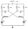
Just a few comments on your circuit. It's been a long time since I've built an oscillator like this, but two things, your RC time constant may be a bit short, like increase the cap size to 1 mfd or the resistor to 10K and I would suggest adding a resistor to the base of each transistor to limit the base current.Originally posted by b28_82
here we go And the LEDS are 2.1v, 25mA, 6.3mcd
That being said, this circuit is no less than 40 years old. 555's aren't too much better age-wise, about 30 years old, but I'd go with them simply because you can sink or source around 200 mA of current without transistors, and an oscillator only requires two resistors and a cap. Also, it has a wide operating voltage range.
F
Fred_M
556s are sometimes cheaper than 555s. A 556 is a double 555 and will work as a single 555 if you just use 1/2 of it. Downside is it's about 170% longer than a 555. Plus side is it can run 2 different circuits or, to an extent, it's its own spare FRED
FREDThanks for the inputs. The 555s at Radio Shack are 1.29 ea. I'm assuming that you control the frequency of the flash with the resistors. I was sorta hopeing that i could make it work with analog components for personal satisfaction I'll probably break down and get one of those 555s or since the largest ceramic caps they sell is .1uF i'll order online.
I'll probably break down and get one of those 555s or since the largest ceramic caps they sell is .1uF i'll order online.Freq. and pulse width are controlled by a combonation of R1, R2 and C1. There is a calculator at the first link I posted. The old way was with charts, which you might find on-line. I like to use trimpots for the resistors, so it can be tweeked because it never seems to come out quite right. Then I sometimes build a fixed resistor to match the measured value of the trimpot after getting it right. This is done by soldering together several resistors. The second link is a 555 tutorial. It's quite a fun animal to play with.