Here's the One I'll really build

Jun 30, 2003
678
0
16
54
Raleigh, NC
Visit site
well, as I mentioned in 'Eek! the Cost', the first railroad plan had just WAY too many turnouts to be affordable.

Here are plans for the layout I will be building on that door.

this is what I will start with, with no scenery or notes on elevation, other than the white-blue is a planned tunnel area
 

Attachments

  • layout_30-b-no-scenic..jpg
    layout_30-b-no-scenic..jpg
    31.6 KB · Views: 681
Jun 30, 2003
678
0
16
54
Raleigh, NC
Visit site
next pic

here it is with planned Scenery.

This is intended to be an Appalachian short line. with a small town on the right and a small mountain on the left, , noted by the ridge line, with a stream running through the upper central region, the siding in the town will be a small factory or a large warehouse, possibly a farmers Co-op or grain silo. The siding on the Left is either a mine (perhaps a gem mine, to be different) or its a tunnel that leads to the 'rest of the railroad'. the black line is a road (note the use of 2 Re-railers as rural grade crossings). the Upper right siding is the interchange track with the class one railroad.

The grey track is 'base level' (1/2" of foam), the yellow is ascending, the blue is the tunnel (still level 0) and the green is elevated between 1 11/16" and 2"
 

Attachments

  • layout 030-scenick-a.jpg
    layout 030-scenick-a.jpg
    42.8 KB · Views: 688
Jun 30, 2003
678
0
16
54
Raleigh, NC
Visit site
Slight modification

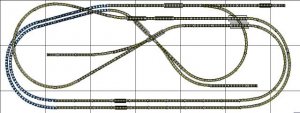
Here is the image again, slightly modified
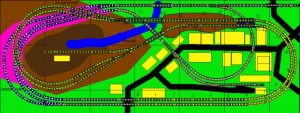
I have removed the straightline passing sidings, because of the difficulty of turnouts on Piers. It has been shifted into the tunnel area now.
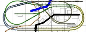
the colors:

Track:
Grey: lvl 0. sitting on top of the 1/2" of foam base.
Blue: lvl 0. Track inside tunnel
Green: elevated track at 12-14 (1-11/16 to 2" high)
Yellow: Climbing track. Grade is 2.8%, and the numbers indicate the appropriate Atlas Pier (in 9/64" inch increments)
Dark Blue outline: Bridges
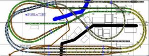
Red dots: insulation points.


Terrain:
Green: basic grass
Blue: a stream running down the mountain and off the board
Yellow: buildings, not specific but gives an idea of the town
Thick black Lines: Roads, note clever use of rerailers for crossings. :D
Brown: mountain, rough height 2". Note: the skinny mountain at right center may end up just being a collection of piers forming and elevated railroad.
Dark Brown: mountain higher than 2", note the spur disappears into the mountain.
Dark Brown: mountain areas higher than 2"
Purple/Pink: rough tunnel area. wide area to left side will be open to allow access in case of derailments or similar troubles.
 

Attachments

  • layout 030-scenick-b-color.jpg
    layout 030-scenick-b-color.jpg
    45 KB · Views: 709

Russ Bellinis

Active Member
Feb 13, 2003
4,501
0
36
78
Lakewood, Ca.
Visit site
Re: Slight modification

Originally posted by screwysquirrel
Note: the skinny mountain at right center may end up just being a collection of piers forming and elevated railroad.

Actually, that would be a place where you could expect the prototype to use a fill.
 
Jun 30, 2003
678
0
16
54
Raleigh, NC
Visit site
Adding some switching

well, after picking up a Lifelike SW9, a favorite loco design, I decided to add some switching options to the layout.

I removed the passing sidings (meaning only 1 train rolling at a time on the main!) I came up with two options and would like opinions on operational possibilities with each, Also note that I'm going to follow the overwhelming consensus and put in a single uniform 2% grade, instead of piers and viaducts to climb at 2.8% rade. Currently thinking of using the woodland Scenic incline to do it if someone tells me the easy way to cover up its zig-zag shape! Preferably one with minimal messiness!


The two trackplans will follow, with commentary
 
Jun 30, 2003
678
0
16
54
Raleigh, NC
Visit site
Option 1

This option has the switching area has only 1 link to the mainline area, and has its own small run-around area and 3 spurs running off the top end of the runaround

In theory you can add 1 more short spur on the lower right side, but I'm out of turnouts right now.

As it stands, this plan, has 93.25" of car storage on it. at 3" per 40' car, thats room for 31 cars(!), probly a bit fewer when accounting for couplers. Of course, the spurs would be unusable if all that was stored there at the same time :)

this plan would allow two train operation, as long as the switcher stays on the orange track
 

Attachments

  • layout 030-e3.gif
    layout 030-e3.gif
    45.5 KB · Views: 395
Jun 30, 2003
678
0
16
54
Raleigh, NC
Visit site
Option 2

This layout is fairly similar. However, it connects with the main in 2 places, and uses the inner (9.75 radius) tunnel loop on the main as a runaround. Here There are two long sidings coming off the lower-center part of the main, with 1 switchback siding, and a switchback link back to the main. The switchback to the main makes the industry area a reversing section. Not a problem as the switching area will have its own power pack, and will be electrically isolated. The runaround section of the main will probably have to be cab selectable. It may need to be wired as a reversing section

I like the look of this one a little better, but the wiring is more daunting

Two train operation is still possible this way, but isn't as easy, since your switcher will be using the single-track main as a runaround! The switcher will usually have to wait until the mainline train runs by to make its own move, then hustle back to the switch area!

This variant has an impressive 119" of space, if you filled it, enough for 39 ( :eek: ) 40-foot cars, though again, you couldn't switch the industries that way.
 

Attachments

  • layout 030-e2.gif
    layout 030-e2.gif
    48.3 KB · Views: 393

Russ Bellinis

Active Member
Feb 13, 2003
4,501
0
36
78
Lakewood, Ca.
Visit site
If you build the second one, and plan to add two switches later as money is available, you could put a crossover in between the two bottom orange tracks with one switch between the two switches on the upper of the two tracks. That would give you nice runaround track in the industrial area. If you put in two switches past the switches in the upper track you would have a longer runaround; but it might require a curved turnout. One more thing to check. I think your industrial section constitutes a reversing section, but I'm not sure. I got a little "dizzy" trying to follow it all the way around.
 
Jun 30, 2003
678
0
16
54
Raleigh, NC
Visit site
Originally posted by Russ Bellinis
If you build the second one, and plan to add two switches later as money is available, you could put a crossover in between the two bottom orange tracks with one switch between the two switches on the upper of the two tracks. That would give you nice runaround track in the industrial area. If you put in two switches past the switches in the upper track you would have a longer runaround; but it might require a curved turnout. One more thing to check. I think your industrial section constitutes a reversing section, but I'm not sure. I got a little "dizzy" trying to follow it all the way around.

I've tested it: The place to add a crossover for max runaround space is the upward bend in the upper of the two long sidings. place a left turnout so the curve follows the existing curve. you can then add a right turnout directly across it, and connect its curved section to the straight of the first turnout :)

As for the reversing section, yes. it does (to see it, start in the lower end, where it connects to the main. Follow that curve around (itrs grey, then blue in the tunnel, then grey again) into the switch that takes it back to the switching area. if you run through that curved section onto the upper siding, you then back up into the main where you first arrived.

Since I'm going to fully isolate the switching zone with its own powerpack, I think the reversing section is migitated. Inside the switching zone, its not a reverse section, and shouldn't need futher special wiring. The loop section *might* need it though
 

60103

Pooh Bah
Mar 25, 2002
4,754
0
36
Brampton, Ontario, Canada
Visit site
SS:
The loop should need no special wiring.
You could eliminate the reversing section effect by connecting the switching section to the outer track at the bottom, by putting a crossing instaed of the switch in the inner track and moving the switch to the outer track. Might change your operations a bit, though.
Ther is no problem with wiring reversing loops -- you can get Atlas components ready wired for your layout.
You might find a problem going from the switching area to the main line if you don't have all wheel pickup on a loco -- say one where the loco picks up RHS and the tender picks up LHS and they sit on each side of the insulated gaps.
Check the wiring by stretching the layout out into a long oval with the switching section off on one side -- you'll see that there are no more problems.