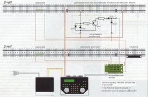
Electronics, occupancy detector

rschroots

New Member
Jan 25, 2004
8
0
1
El Paso, Texas
Visit site
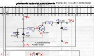
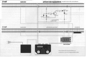
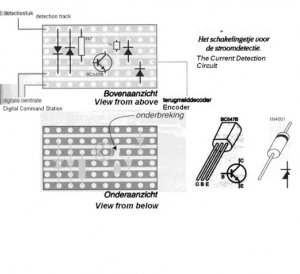
I built a little circuit for current detection. I have the schematic. It doesn't seem to work. Anyone feeling competent to tackle this?
I will send you the schematic, and ask some detail questions on how to measure the circuit.

thanks,

Rolf
 

ezdays

Out AZ way
Feb 3, 2003
6,339
0
36
Arizona
bigbluetrains.com
Originally posted by rschroots
Thanks for all the replies. My schematics are too big to post them here. If you give me you e-mail adress, I'll send them attached.

Thanks.
You can send someone an email by clicking on the "profile" button below one of their posts, but you can't include an attachment that way. I will PM you with my address. This is a precaution to prevent public display of email addresses and keeps them from being harvested by spammers.
 

krokodil

Member
Nov 20, 2003
218
0
16
Austria
www.railfilm.net
Hi to everybody.


on the schematics there are different things wrong.

First of all the polarity.

To open the transistor you must have on TP1 positiv potential, on the schematic this point is connected to the minus bus (left side bottom).

Second.

The circuit will work only in one direction when on the TP2 is minus and on the TP1 is plus.

Third

Of course either one of the D3 or D4 diodes must be a LED to indicate the occupancy, or the output of the circuitry is not the TP3 but the common point of the R2 an Q1 C (collector). On TP3 you will have always full voltage from the power pack.

Summary

The circuitry will not work very well when you use the same power pack for the train and for the detector. (in your case the - terminal is connected to the top rail, the plus terminal to the bottom rail).
I would suggest to use a separate power pack with a common point /Terminal TP2/ with the main power pack, while the another terminal of the power pack will be connected to the upper rail, the second (positive) terminal of the auxiliary power pack (12 - 16 V DC) can be connected to each TP1).

I hope you could follow my English.

:wave:
 

jon-monon

Active Member
Aug 15, 2002
4,590
0
36
59
Cobblers Knob, IN
www.2guyzandsumtrains.com
Thank you Krokodil! Your English is great!

I've reversed the polarity in the drawing above, and I'm attaching hte original, but it might be too small to read.

I'm 3/4 asleep and 1/4 dead today, so I also forgot to mention:

- I added all the red and blue labels for our discussions

- The diode at the bottom was added and labeled for our discussions (you can say "measure cathode D1, and it will make more sense to a novice). The polarities are shown to indicate forward bias.
 

Attachments

  • railhobbysmall.jpg
    railhobbysmall.jpg
    57.9 KB · Views: 134

krokodil

Member
Nov 20, 2003
218
0
16
Austria
www.railfilm.net
Hi jon-monon

it is better, but still there is a problem. What is the voltage on the encoder output which is connected to the TP1 (the first drawing) and what is the voltage on the encoder terminal connected to the TP3 (original drawing).

As the active state of your occupancy detector is the switched Q1 (low impedance between the C and E, the additional R2 makes it only worse (the Q1 cannot pull down the TP3 to 0 V.
Usually this resistor is already included in the input circuitry of the floowing electronics (CMOS or TTL Gates), and via this resistor the circuitry automaticall pulls UP the Q1 C when there is no occupancy. When the train arrives to the block, the Q1 pulls down the C voltage to 0 V and this must also appear on the input of the following electronics. In you case the pull down power is split between the internal resistor and the R2, so in many cases you can hardly pull down the voltage on TP3 to the half of the full power pack voltage Ucc - and this does not work - will not be detected as occupancy, because many electronic gates required for low leve less than 1/3 of the Ucc.
 

jon-monon

Active Member
Aug 15, 2002
4,590
0
36
59
Cobblers Knob, IN
www.2guyzandsumtrains.com
Originally posted by krokodil

Usually this resistor is already included in the input circuitry of the floowing electronics (CMOS or TTL Gates), and via this resistor the circuitry automaticall pulls UP the Q1 C when there is no occupancy. When the train arrives to the block, the Q1 pulls down the C voltage to 0 V and this must also appear on the input of the following electronics. In you case the pull down power is split between the internal resistor and the R2, so in many cases you can hardly pull down the voltage on TP3 to the half of the full power pack voltage Ucc - and this does not work - will not be detected as occupancy, because many electronic gates required for low leve less than 1/3 of the Ucc.

Do you think the value o fR2 should be reduced?
 

rschroots

New Member
Jan 25, 2004
8
0
1
El Paso, Texas
Visit site
As the circuit is used in a DCC environment, there is AC on the track. So it will work, or not, regardless of polarity.That's what the anti-parallel diodes D1 and D2 are for.
I'll quote from the article I got this from, some of the explanation of why this should work:
When a "current drawer" (i.e. an engine) runs on the insolated track section, a little voltage difference exists over D1 and D2. The transistor amplifies this voltage difference, and thus signals the encoder (thru TP3).

When I measured the circuit, I didn't see any voltage between TP3 and TP1 or between TP3 and TP2, neither with the track occupied nor unoccupied.
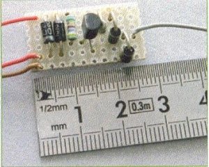
I made 5 circuits on a little board, all completely independent from each other. Measuring the circuits, when not connected to the outer world, on 4 there was conductivity between TP1(+) and TP3(-), and on one the was no conductivity that way.

Any more ideas?
 

krokodil

Member
Nov 20, 2003
218
0
16
Austria
www.railfilm.net
Hi everybody.

There are few confusions.

a.
The circuit will work on DCC when the basic conditions for the transistor circuitry are given, i.e. it has the correct polarity. (Emitter negative, collector positive).
You cannot simple swap the polarity.
b.
The circuit will indicate the occupancy only during the positive voltage period of the DCC circuit (the antiparallel diode on the front has nothing to do with it, it blocks only the negative voltage from the basis out, the transistor will switch only to positive polarity on the input).
c.
With voltmeter it is very difficult to measure, because the output of the circuit has the same pulses as the DCC what you will not see on any commercial voltmeter (they are to slow).
d. the output stage is a bad design, probably a mistake on the drawing. The real output is not on the common point of the diode and the resistor, see later.
d.
I do not know exactly the function of the following encoder (probably a factory made box). For that reason the analysis is for me extremely difficult. I simple cannot believe that they are going to analyse the jumping (with DCC frequency) output of the transistor, i.e. the occupancy detector in dynamic mode with the same frequency as the DCC is. This would be very bad from many different points of view....
e.
The circuitry is far too simple for reliable work. (probably it was made by a designer, who never had a train under the Xmas tree.
f.
To indicate the function of the detector I would replace at least in this stage one of the output diodes D4 with a RED LED, which will lit when the Q1 switches (does not matter of the DCC frequency).

My suggestions:

1. Any "normal" occupancy detector must have some kind of decay. The model train is not that reliable, that the current is always there. This circuitry in such case will indicate the train in the next moment will not. To avoid this you have to add a bigger capacitor (tantal at least 50uF/20V, + leg to the C of the Q1, - leg to TP2) to the output. This will change also the function of the circuit and will switch continuosly to zero voltage when the block is occupied (you can measure it with voltmeter). And remains switched for a while also after the train leaves - I prefer about 1 second. This gives you a reliability for poor contact and detects also cars with resistors between the wheels.

2. The output is a bad design. The output must be the point where the collector C the Q1 is connected to the R2. I.e. the D3 cathode must be wired to this point, the D4 cathode to the end of the resistor R2.

3. Probably a single diode on the input (D1 and D2) is not enough to switch the transistors - the basis usually requires about 0.7V to switch on the most modernSi diodes you can get in forward biased mode something about 0.6V. In a more professional design there are two diodes in series instead of a single D1 and one in oposite direction (D2), which gives about 1.2 V on the input when occupied. This is more then enough to switch the Q1.

4. For a much more better design with OPAMPs you can use only similar two diodes as in this circuitry, (and you will really detect in both direction), but this is much more complex circuitry (see MR about 2 years ago).


Good luck, and never trust such simple circuitry (7 components, and how many problems)....

B]model railroad is more serious then many electronic designers ever dreamed about.[/B]

:mad: :curse: :thumb:[
 

jon-monon

Active Member
Aug 15, 2002
4,590
0
36
59
Cobblers Knob, IN
www.2guyzandsumtrains.com
As krokodil stated it may be difficult to measure with just a voltmeter. It's probably best to just double check all the connections and measure continuity with power off. If it all appears to be in order, it may just be incompatable as designed.

I am wondering, if you have reed switches, why bother with current detection? Reed switches are ultra relaiable and work independant of DC/DCC track voltages. For many years I used to work on a junky robotic product that was covered with reed switches. The reeds were the only thing reliable about it, with not a single failure, except when smashed by humans :D
 

rschroots

New Member
Jan 25, 2004
8
0
1
El Paso, Texas
Visit site
Ad. d. from Krokodil:
The encoder could be a "Rückmeldemodul" from Conrad/Völkner (Art.-Nr. 016-438-8), but the circuit is intended to work with any encoder. The circuit is meant as a do-it-yourself in place of a Lenz LB100 current detector.

In response to jon-monon:
I am using N-scale. I do use reed contacts, and magnets on my engines, but I'd rather not depend on engines having to have a magnet, and I find putting the reed contacts in the track a hassle.

:)