DCC and Bachmann Spec F7 A/B

skipgear

New Member
May 15, 2005
78
0
6
55
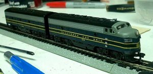
Does anybody have any links or suggestions to installing DCC decoders in the Bachmann F7 A/B sets?

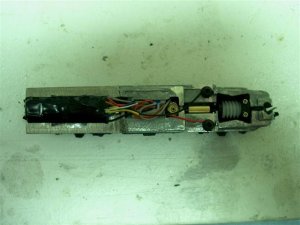
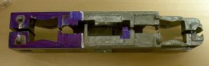
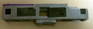
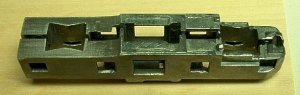
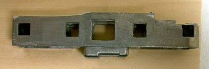
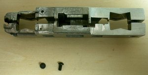
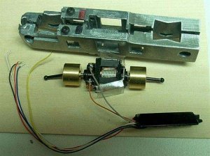
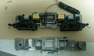
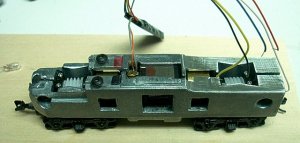
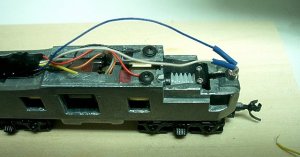
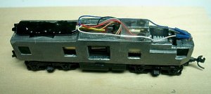
It looks a decoder will just fit between the top of the frame and the shell but I think I am going to have to do a little milling to get some extra space. I also need to modify the frames to issolate the motor.
 

ross31r

Member
Jul 6, 2004
314
0
16
40
Surrey, United Kingdom
AFAIK, you cant do it without getting the Aztec Models frame for the units - i posted this question up a few months ago.

Hence i have abandoned my F7 ABA set and switched to Kato and Intermountain Fs and FTs for my N Gauge
 

skipgear

New Member
May 15, 2005
78
0
6
55
There is no need for the Aztec frames, the modifications are not hard to do at all. It takes about 10 minutes with a dremel tool to get them ready.

I have completed the B Unit and will try to take pictures when I do the A for a quick tutorial. The conversion can be done completely with a dremel tool, sanding drum and 1/16 drill bit. I used a belt sander to make things go a little faster removing material from the frame. I still need to decide how I am going to tackle the headlight on the A unit but I don't think that will be very difficult. The fix I have in mind might actually help stop the light leakage into the cab of the loco.

Attached are two images of the decoder installed in the B unit.
 

Attachments

  • IM004675 (Small).JPG
    IM004675 (Small).JPG
    38.8 KB · Views: 59
  • IM004677 (Small).JPG
    IM004677 (Small).JPG
    36.2 KB · Views: 49

skipgear

New Member
May 15, 2005
78
0
6
55
The loco's are from the most recent batch from Bachmann. I have an older standard Bachmann F7 (at least 5 years old) that has the same style frame. As far as I can tell, the difference between the two is much better printing/paintjob and the 5 pole motor vs. the 3 pole in the standard.

As far as the decoder, I am doing these for a friend and that is what he handed me. I have done a half dozzen different loco's for him with these decoders and all are working fine, although we did have one that was DOA.
 

skipgear

New Member
May 15, 2005
78
0
6
55
F7 DCC Install Step by Step (Step1)

Step 1 - Disassemble the loco.

Everything is pretty straight forward. Before removing the motor from the frame, mark the top side of the motor with an orange marker if you have it. The orange DCC wire will eventually connect to this terminal. Make sure to remove the small contact spring from the left frame. Note the front truck and rear truck of the unit so they can be reinstalled in the same location. This is important if you have already broken in the motor, the gears have worn to a match and you don't want to change them around and have to go through break in again. Straighten the leads on the headlight for later. If you haven't installed MT couplers yet, do it now while things are apart, it is much easier.


Attachments

  • Step1Dissasembly.jpg
    Step1Dissasembly.jpg
    56.7 KB · Views: 49
  • Step1HILITE.jpg
    Step1HILITE.jpg
    64.1 KB · Views: 48

skipgear

New Member
May 15, 2005
78
0
6
55
Step 2 - Mark the frame for modification.

Mark the frame as shown. The area removed from the upper rear can be adjusted to suit the size of your decoder. Make sure to mark the small tab from the right side frame for removal. It acts as a motor contact so enough must be removed so it will no longer make contact.


Attachments

  • Step2PreparationA.jpg
    Step2PreparationA.jpg
    34.1 KB · Views: 50
  • Step2PreparationB.jpg
    Step2PreparationB.jpg
    31.4 KB · Views: 43

skipgear

New Member
May 15, 2005
78
0
6
55
Step 3 - Modify the frames.

Remove the material in the marked areas using your favorite tool for the job. I screwed the frames back together and used a bench top belt/disc sander for roughing out the large area then a Dremel and files to clean it up and make the final fit. Take the frames back apart and use a Dremel or file to remove the tab. After you have removed the needed areas, clean the frames with soap and water to remove any shavings and filings. Then check to make sure the motor terminals no longer make contact with the frame.


Attachments

  • Step3ModifyA.jpg
    Step3ModifyA.jpg
    38.5 KB · Views: 45
  • Step3ModifyB.jpg
    Step3ModifyB.jpg
    37.7 KB · Views: 40

skipgear

New Member
May 15, 2005
78
0
6
55
Step 4 - Adding main power connections.

Since you cannot solder to the pot metal frames, you must create a screw contact to attach the main power leads of the DCC decoder. Size is really up to what you have available to you. I used 2-56 button heads because I have plenty from my RC racing equipment. Drill a hole appropriate to the screw and tap you will be using in the place shown. There is a cavity in the casting directly below the hole placement so you don't have to drill very far to break through to the inside of the frame. After drilling, tap the holes and make sure that the screws are not too long and protrude into the flywheel pocket. If they are too long, shorten them so that they won't hit the flywheel. Mark the right frame with Red and the left frame with Black (shown in the next step).


Attachments

  • Step4Contacts.jpg
    Step4Contacts.jpg
    47.2 KB · Views: 46

skipgear

New Member
May 15, 2005
78
0
6
55
Step 5 - Installing the DCC decoder.

Now you need to attach the decoder to the motor. The orange wire will connect to the top terminal and the gray wire will connect to the bottom terminal of the motor. Remember marking the top of the motor with an orange marker in the beginning. If you didn't mark the motor, another easy way to tell is the plastic insulating shield has a hole punched in the bottom flap. Cut the DCC leads down to the minimum length you feel comfortable with. For the MRC decoder shown, the Gray wire was 1.5" and the Orange was 1.25" long. Solder the wires as shown, making sure to use the least amount of heat and solder so as not to melt the plastic of the motor. Also make sure you don't leave any solder blobs on the connection, if the joint is too thick, there is a chance it could contact the side of the frame when you reassemble things.


Attachments

  • Step5InstallDCC.jpg
    Step5InstallDCC.jpg
    65.7 KB · Views: 50

skipgear

New Member
May 15, 2005
78
0
6
55
Step 6 - Reassemble the frames.

Reinstall the motor in the right frame. Then install the trucks. Now is a good time to make sure the contact wipers on the trucks are bent properly and clean. Also note the plastic insulating washers between the side frames, they are cut different for the front and rear. Don't forget the plastic insert for the fuel tank mounting screw. Carefully replace the left frame making sure to line everything up and not catch the pickup wipers on the inside of the frame. Screw the frames together, checking for binding as you go.


Attachments

  • Step6ReassembleA.jpg
    Step6ReassembleA.jpg
    33.8 KB · Views: 45
  • Step6ReassembleB.jpg
    Step6ReassembleB.jpg
    51.8 KB · Views: 48

skipgear

New Member
May 15, 2005
78
0
6
55
Step 7 - Headlight and Main power connections.

First cut the red and black wires to length and install them on the appropriately marked post. Next cut the wires on the headlight shorter, aprox. .25" final length. Cut the wires on the DCC (Blue & White) to the right length, slide a .25-.5" piece of small heat shrink tube on each of the blue and white wires, then solder them to the headlight. It doesn't matter which wire goes to which lead of the bulb. Slide the heatshrink over the connection to insulate them and then replace the bulb in it's original place. I used some double sided scotch tape to mount the decoder to the top of the frame. It also added an extra layer of isolation from the frames. It is a good idea to tape down the wires to make it easier to replace the shell and keep them out of the gears.


Attachments

  • Step7Headlight.jpg
    Step7Headlight.jpg
    52.2 KB · Views: 44

skipgear

New Member
May 15, 2005
78
0
6
55
Step 8 - You're Done

Place it on the test track make sure it works. Program the decoder.

Step 9 - Replace the shell and have fun.


Attachments

  • Step8Test.jpg
    Step8Test.jpg
    48.2 KB · Views: 37
  • Step9FinishedProduct.jpg
    Step9FinishedProduct.jpg
    32.2 KB · Views: 18

skipgear

New Member
May 15, 2005
78
0
6
55
Ross, I wouldn't mind doing them but by the time you add in the cost of shipping them from the UK, and then return shipping, would it be worth it?