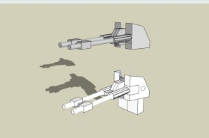
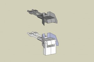
Fantastic! This will bring the model closer to perfection. I'm currently working on the revised turret construction. Stay tuned, folks! 
Colonial Landram from Battlestar Galactica
- Thread starter Revell-Fan
- Start date
You are using an out of date browser. It may not display this or other websites correctly.
You should upgrade or use an alternative browser.
You should upgrade or use an alternative browser.
I really like the look of this new turret! I am looking forward to building it!
POWER SLED UPDATE INCOMING!
As you might know the BSG BluRay release has provided me with much better images of the vehicles and props used in the show. This allows me to revisit the models I have released in the past and to accurize them. One of these models is the Power Sled.
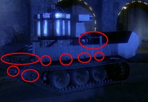
This image shows some of the areas which are being changed and updated. Stay tuned!
As you might know the BSG BluRay release has provided me with much better images of the vehicles and props used in the show. This allows me to revisit the models I have released in the past and to accurize them. One of these models is the Power Sled.

This image shows some of the areas which are being changed and updated. Stay tuned!
I am looking forward to trying my hand at building this new revised model.
- Apr 5, 2013
- 13,498
- 9,549
- 228
I'm still busy updating the Power Sled file. It is not complete yet but I can show you what I have done so far.
The wheels got some new parts for laminating to spruce them up a bit:
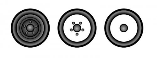
Only the wheels that face outward are laminated. If you laminate the wheels facing toward the vehicle's chassis the glue are is reduced which might make the mounting unstable. A lamination set for the inner wheels will come with the detailed wheels and tracks add-on set.
The wheel box mount parts were combined to one solid piece. That way you will be able to push axles through as a first step toward the aforementioned add-on set.
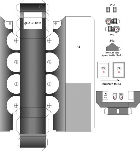
You can see the new towing hook 23.
An inner skeleton with cutting marks for the add-on:
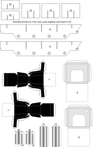
You can also see two new seats 3. The Bluray showed that there was a passenger seat. In addition, there is a bar behind the driver as well (24 & 25). It is attached to the light tower 2:
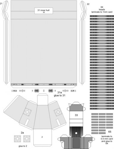
New tracks graphics and additional parts bring the model much closer to what we can see on the screen. Part 33 is the new motor box.
And this is the piece that started the revision:
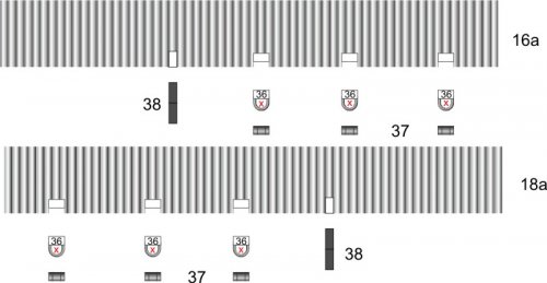
The new separate parts 16a & 18a are to be laminated to the sides. 36 are hangers that dangle down from the sides.
The plans are almost ready for testing. Stay tuned!
The wheels got some new parts for laminating to spruce them up a bit:

Only the wheels that face outward are laminated. If you laminate the wheels facing toward the vehicle's chassis the glue are is reduced which might make the mounting unstable. A lamination set for the inner wheels will come with the detailed wheels and tracks add-on set.
The wheel box mount parts were combined to one solid piece. That way you will be able to push axles through as a first step toward the aforementioned add-on set.

You can see the new towing hook 23.
An inner skeleton with cutting marks for the add-on:

You can also see two new seats 3. The Bluray showed that there was a passenger seat. In addition, there is a bar behind the driver as well (24 & 25). It is attached to the light tower 2:

New tracks graphics and additional parts bring the model much closer to what we can see on the screen. Part 33 is the new motor box.
And this is the piece that started the revision:

The new separate parts 16a & 18a are to be laminated to the sides. 36 are hangers that dangle down from the sides.
The plans are almost ready for testing. Stay tuned!
Last edited:
I have to say that these new parts look AMAZING! This model is being taken to a whole new level!
While Chris is testing the new Sled pattern I have swung into action to complete the makeover of the Landram turret. I noticed that the swivel joint position was wrong. It must be hidden inside the turret. Like the Sled the Landram will receive additional parts for laminating and several texture updates. Stay tuned! 
I have revamped the undercarriage of the Landram 34 so that it matches the one from the Power Sled.
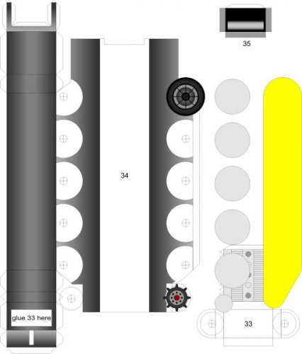
The wheel elements were not aligned correctly, so I rebuilt them and centered everything. Now they are symmetrical.
I re-aligned everything and moved the sprocketed wheel down so that it matches the config of a real tracked vehicle. In the former config the wheel sat too high which would have resulted in a floating track. You can also see the first drawing of the new motor box 33.
The yellow piece on the right will be turned into a mockup to find out how long the new tracks are supposed to be. If everything works as planned this mockup will become part of the new kit because it could help in pre-shaping the new track parts just like the wing calibrator that comes with the Colonial Viper. In theory it will be turned into a solid block. Then the tracks are laid around it and glued together. Once assembled they are pulled off of the mockup and pushed over the wheels on the model.
Alright, here we go again! 
I already explained the basic procedure but here are some pictures for you to fully understand the principle.
First you build the track former (or shaper).
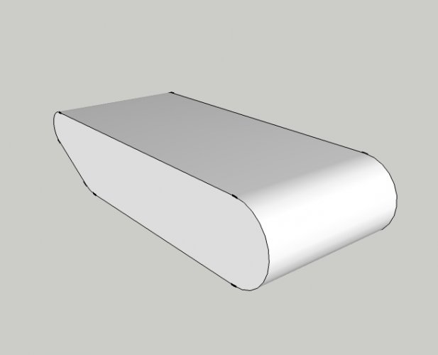
Then the various belt strips are wrapped around and glued together.
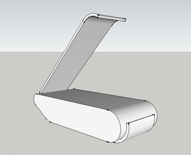
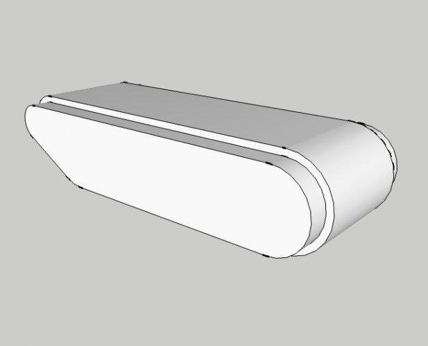
Then you pull off the completed track
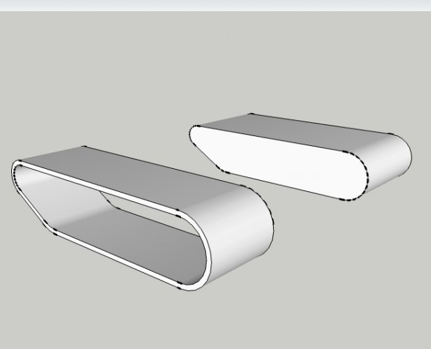
And push it over the wheels of the vehicle.
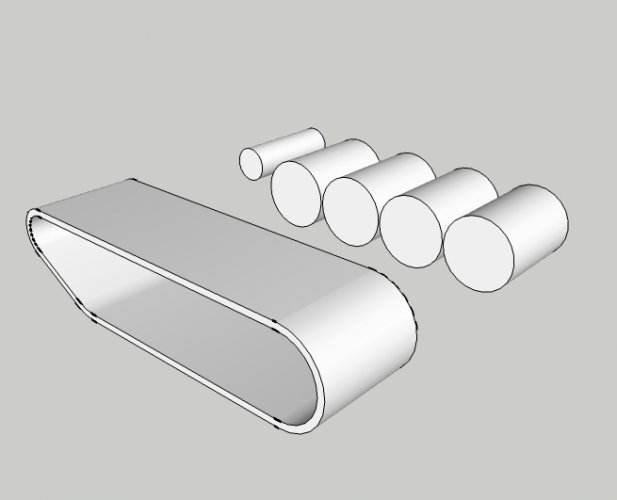
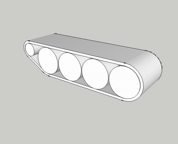
The wrapping will ensure that the curvature of the tracks is maintained as intended. Any floppyness should be a thing of the past.
One note for those who may be afraid of these super-detailed tracks: This enhancement will be available separately as an addon set. The simple track construction with the wide belt bands will remain part of the original kits in order not to scare off beginners. All corrections of the original models will only affect parts which have clearly proven to be wrong after the BluRay release. The Landram for example will not only get a new turret mount but also a gunner's seat.
The first major task was to determine the new belt lengths. To do so I assembled the former and wrapped paper strips around it.
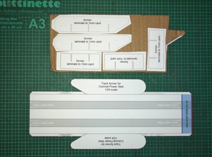
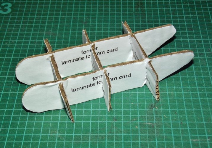
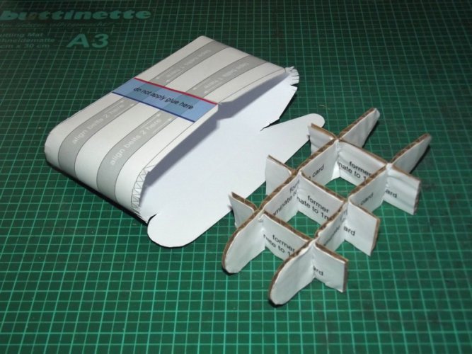
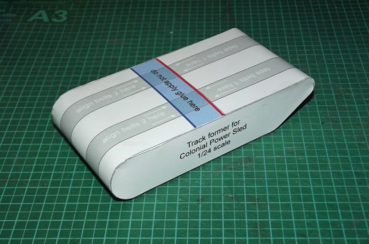
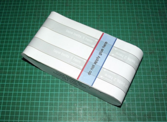
The former has marks on it telling where to attach which belt. This makes sure that all parts are aligned and that you will have an overlapping "flap" to close the tracks later on the wheels.
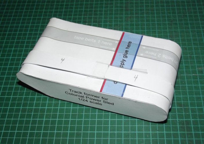
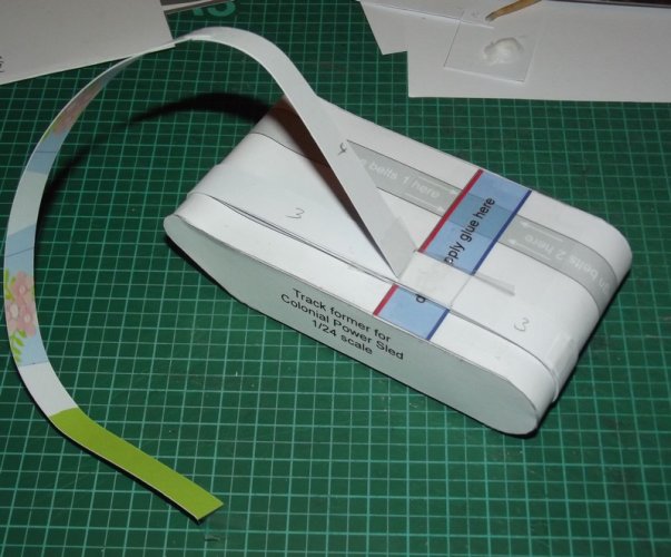
Then I removed the strips again and tape-measured their lengths.
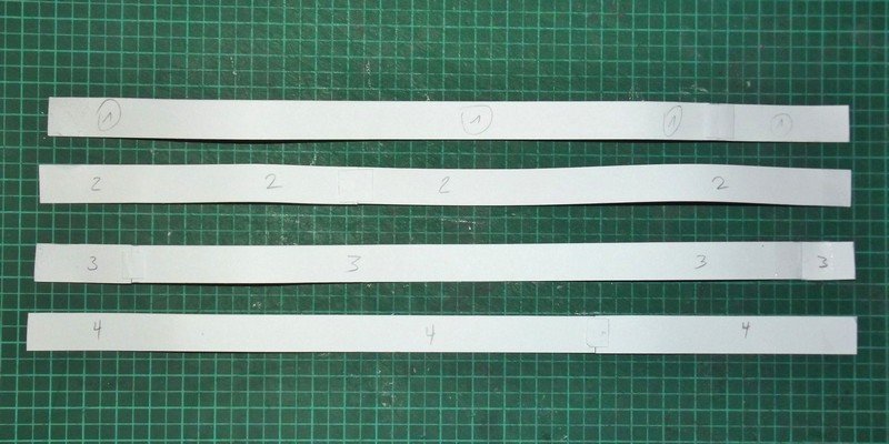
The info was used to adjust the parts in the plans. I'll have to check all the other scales accordingly to make sure that everything fits. I will however add a blank strip which you can use to close any gaps if they appear. Stay tuned!
I already explained the basic procedure but here are some pictures for you to fully understand the principle.
First you build the track former (or shaper).

Then the various belt strips are wrapped around and glued together.


Then you pull off the completed track

And push it over the wheels of the vehicle.


The wrapping will ensure that the curvature of the tracks is maintained as intended. Any floppyness should be a thing of the past.
One note for those who may be afraid of these super-detailed tracks: This enhancement will be available separately as an addon set. The simple track construction with the wide belt bands will remain part of the original kits in order not to scare off beginners. All corrections of the original models will only affect parts which have clearly proven to be wrong after the BluRay release. The Landram for example will not only get a new turret mount but also a gunner's seat.
The first major task was to determine the new belt lengths. To do so I assembled the former and wrapped paper strips around it.


The former has marks on it telling where to attach which belt. This makes sure that all parts are aligned and that you will have an overlapping "flap" to close the tracks later on the wheels.


Then I removed the strips again and tape-measured their lengths.

The info was used to adjust the parts in the plans. I'll have to check all the other scales accordingly to make sure that everything fits. I will however add a blank strip which you can use to close any gaps if they appear. Stay tuned!
Last edited:
Time to get serious!
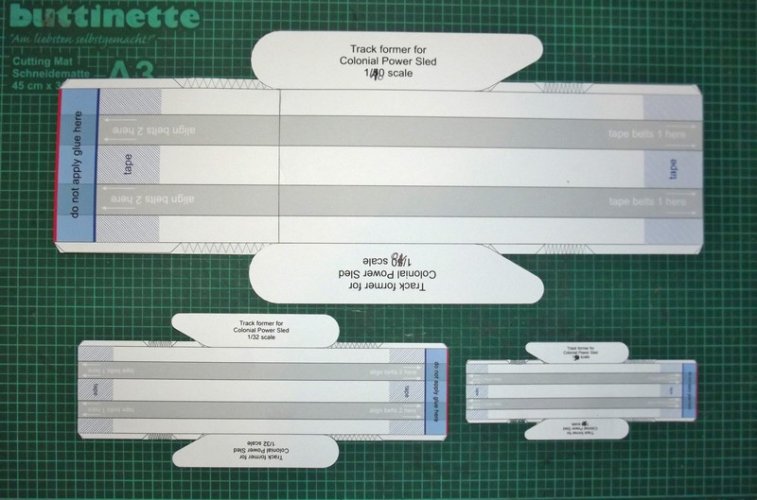
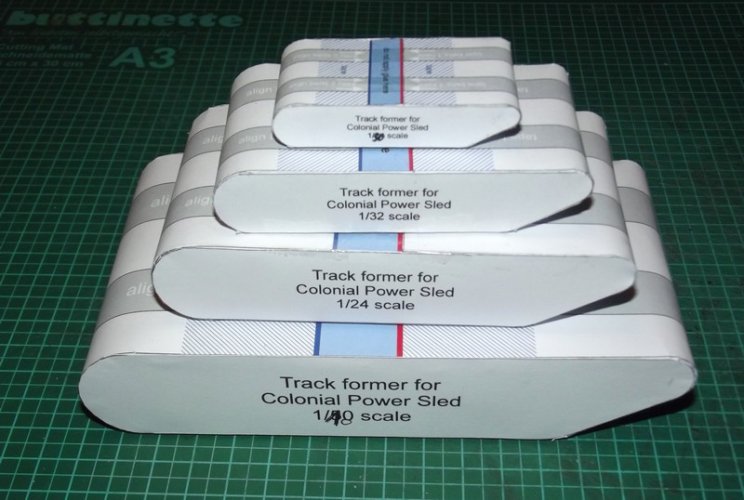
If you stack the formers they will look like a little tank.
The blue-crossed area will be covered by some clear tape.
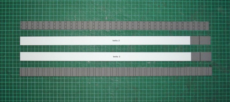
After the measurements the graphics were adapted. My paper is about 0.2mm thick. This is important to make everthing align properly. However, I have made sure that you will get a nice result even if the paper thickness deviates from mine a bit. The crucial area is the spot where the inner and outer belt meet. The inner beef up belts have grey areas which will prevent any white paper showing if the outer / inner belts are a bit too short and do not meet perfectly. So any gap will reveal a dark grey area of about 1mm which is totally acceptable for me. In addition, the spot where they meet sits right below the chassis so if you do not tape-measure the distance between the blades you should not notice anything. Moreover, you can always cut the inner belts shorter once you remove them from the formers and bring the outer belts closer together to achieve a perfect fit, so in essence there should be no problems. This will also give you some wiggle room if the wheel placement requires that (you don't want to put on too tight belts because that would bend the axles ).
).
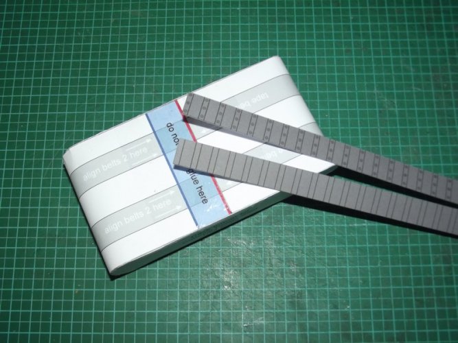
The most important thing is to remember which end you start with. Both the inner and the outer belts feature blade markings which in a perfect world should match. So if you start with the end carrying the blade markings on belt 1 you will need to start with the same end of belt 4.
Pre-shape all belts a bit. It does not have to be exact but you should make them memorize a curvature.
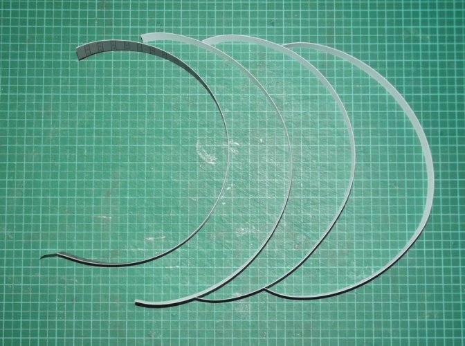
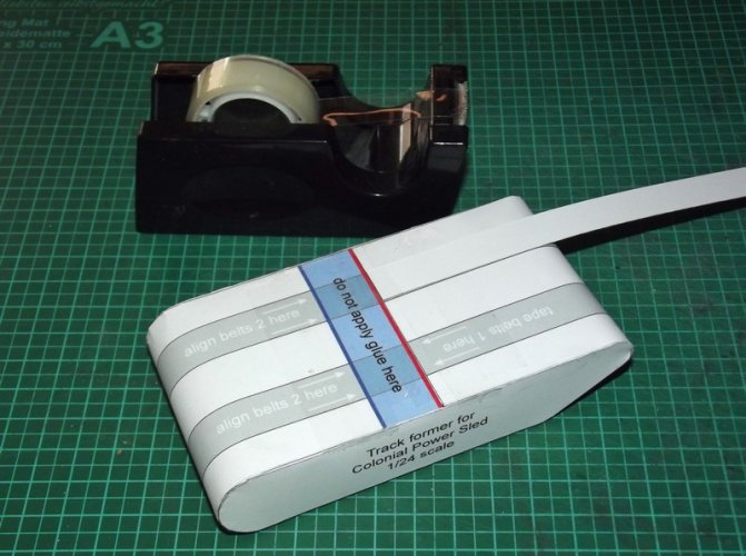
You start with belt 1. Turn it upside down and tape the end you start with to the former. The tape on the former will ensure that the tape on the belt will be detached easily again. That way you will not damage anything and you can re-use the former multiple times. The other end of belt 1 is taped to the former, too.
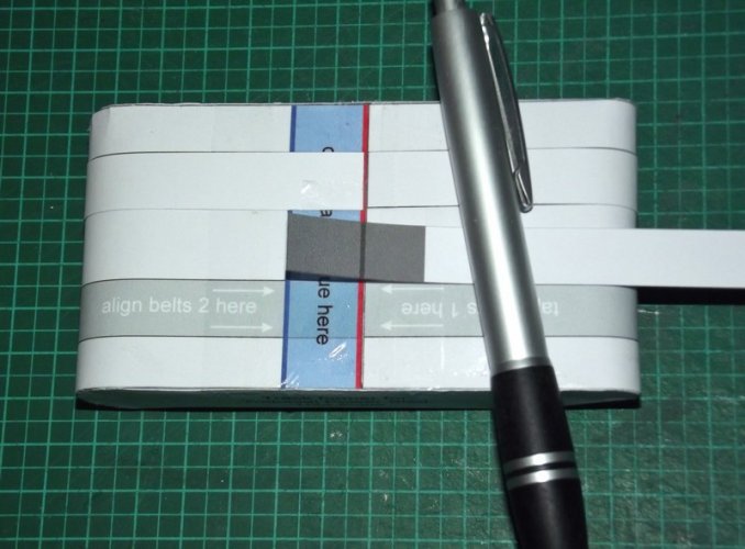
Then comes the first "thickening layer", belt #2. This one is supposed to be aligned with the blue line on the former. That will ensure that you and up with a little tongue which will act as a flap to finally close everything once it is wrapped around the wheels. Belt 2 is again turned upside down after aligning so that the grey area faces the bottom / belt 1.
If you ask me why I chose red and blue markings? To make them easier to see. The first idea was to use green and red, but considering that there are people who cannot see those colours I switched the green to blue to give at least one definitve coloured anchor to turn to.
Now then. Belt #2 is glued all the way round to belt #1. The overlapping end of belt 2 stays loose. If you glue it down, too, you will end up with closed loops and that is not what we want.
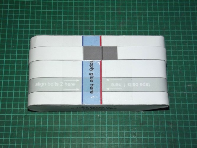
Belt 3 is glued all the way round to belt 2.
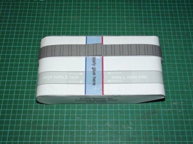
Belt 4 is the outer belt of the track. It again is aligned on the red line and glued to belt 3.
Please keep in mind that belts 1 and 4 are not connected to the inner belts between the red and blue line on the former.
On the final model you would work on both track halves at the same time and add the blades on the former, but since this is just a concept test I'm focusing on the gist for now.
Wait till the glue has fully cured.
Now carefully remove the tape on belt 1.
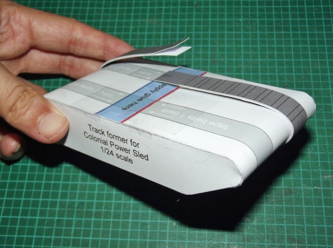
You see a snake mouth on the left and a tongue on the right.
Pull off the track.
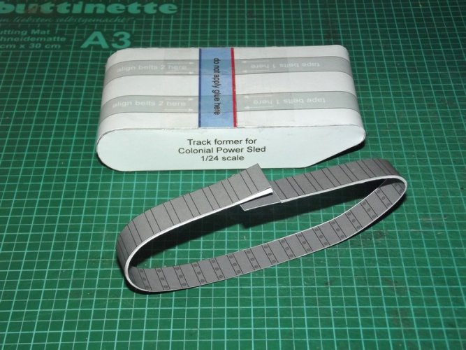
(Now you would add the track guides. )
)
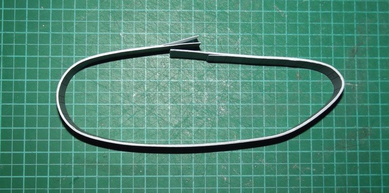
Push it over the wheels (not shown forlaziness complexity reasons). 
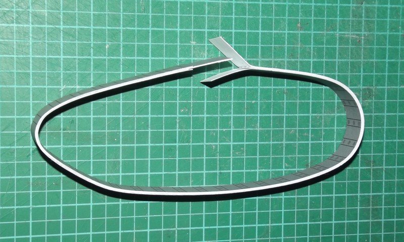
The snake bites in her own tail!
Glue everything together. Adapt the length if necessary.
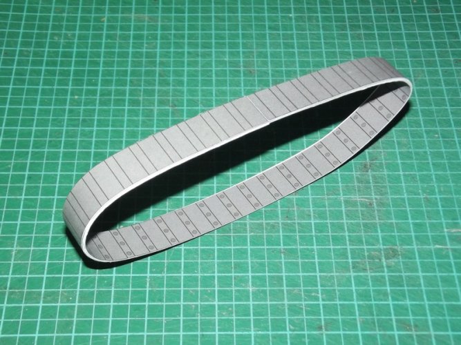
Track complete. Thanks to the alignment marks the blade markings of the inner and outer belts should match. Paint the edges and you are ready to go.


If you stack the formers they will look like a little tank.
The blue-crossed area will be covered by some clear tape.

After the measurements the graphics were adapted. My paper is about 0.2mm thick. This is important to make everthing align properly. However, I have made sure that you will get a nice result even if the paper thickness deviates from mine a bit. The crucial area is the spot where the inner and outer belt meet. The inner beef up belts have grey areas which will prevent any white paper showing if the outer / inner belts are a bit too short and do not meet perfectly. So any gap will reveal a dark grey area of about 1mm which is totally acceptable for me. In addition, the spot where they meet sits right below the chassis so if you do not tape-measure the distance between the blades you should not notice anything. Moreover, you can always cut the inner belts shorter once you remove them from the formers and bring the outer belts closer together to achieve a perfect fit, so in essence there should be no problems. This will also give you some wiggle room if the wheel placement requires that (you don't want to put on too tight belts because that would bend the axles

The most important thing is to remember which end you start with. Both the inner and the outer belts feature blade markings which in a perfect world should match. So if you start with the end carrying the blade markings on belt 1 you will need to start with the same end of belt 4.
Pre-shape all belts a bit. It does not have to be exact but you should make them memorize a curvature.


You start with belt 1. Turn it upside down and tape the end you start with to the former. The tape on the former will ensure that the tape on the belt will be detached easily again. That way you will not damage anything and you can re-use the former multiple times. The other end of belt 1 is taped to the former, too.

Then comes the first "thickening layer", belt #2. This one is supposed to be aligned with the blue line on the former. That will ensure that you and up with a little tongue which will act as a flap to finally close everything once it is wrapped around the wheels. Belt 2 is again turned upside down after aligning so that the grey area faces the bottom / belt 1.
If you ask me why I chose red and blue markings? To make them easier to see. The first idea was to use green and red, but considering that there are people who cannot see those colours I switched the green to blue to give at least one definitve coloured anchor to turn to.
Now then. Belt #2 is glued all the way round to belt #1. The overlapping end of belt 2 stays loose. If you glue it down, too, you will end up with closed loops and that is not what we want.

Belt 3 is glued all the way round to belt 2.

Belt 4 is the outer belt of the track. It again is aligned on the red line and glued to belt 3.
Please keep in mind that belts 1 and 4 are not connected to the inner belts between the red and blue line on the former.
On the final model you would work on both track halves at the same time and add the blades on the former, but since this is just a concept test I'm focusing on the gist for now.
Wait till the glue has fully cured.
Now carefully remove the tape on belt 1.

You see a snake mouth on the left and a tongue on the right.
Pull off the track.

(Now you would add the track guides.

Push it over the wheels (not shown for

The snake bites in her own tail!
Glue everything together. Adapt the length if necessary.

Track complete. Thanks to the alignment marks the blade markings of the inner and outer belts should match. Paint the edges and you are ready to go.
Last edited:


