TrainNut
Go for it. It's a beautiful locomotive, worthy of your efforts. Just be patient, like you are laying or fussing with track to eliminate derailments. The remaining work is no more difficult than the disassembly or trackwork - just more of it.
Before beginning, buy your decoder and speaker(s) of choice. Decide whether or not to keep the existing motor (it's easy to change out if you want to and the folks at NWSL will certainly help you make a good replacement selection), and whether or not you are going to add pickups. Tomar makes some nice pickup kits. Neither is necessary for the DCC conversion.
You will need some model aircraft fuel hose for connecting the motor shaft to the gear box. Epoxy cement and the heat resistant tape sold by the DCC houses, some RTV, plastic screws, some flexible 26-30 gauge wire, and a suitable sheet material for the speaker enclosure pretty much complete the materials list (these items and a willing attitude to learn new skills).
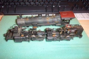
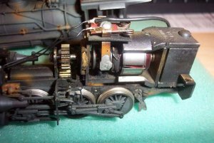
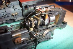
I can't tell for sure from the photos, but it looks like the top spur gear is mounted directly on the motor shaft. If so, that electrical connection has to be broken. The shaft has to be cut with a Dremel and an extra bearing and support added for the gear shaft. The fuel hose is cut to use as a joint between the motor and gear shafts. The motor is mounted on top of a piece of the heat-resistant tape (or RTV) to isolate it from the frame. A plastic screw replaces the metal one used to adjust the motor. Now you have completed the most difficult task of the conversion.
Next, decide whether you are going to install the decoder in the engine or tender.
If the decoder is installed in the engine (probably easier), the motor wires go from the decoder to the motor brushes or terminals. The lighting wires are run to the decoder instead of the motor brushes. One track wire goes from the decoder to the engine frame, the other goes to the wire from the tender drawbar. The speaker wires go separately to the speaker(s) in the tender. That's it for wiring unless you add pickups.
The speaker (assuming the speaker frame is grounded) must be insulated from the tender frame and shell. Use RTV or tape to mount. I recently saw an article on using PVC pipe for a speaker enclosure. The speaker enclosure ideally prevents the speaker vibrations (means close to air-tight) from escaping out the back as lost energy. If reflected back towards the speaker, the vibrations will reinforce at the resonant frequencies of the enclosure cavity - bigger cavity (within reason) means more bass. Drill some holes where you want the sound to come out - either through the coal load or out the bottom of the tender.
Wasn't so bad after all.
If you decide to add pickups, they must wipe against the wheel tread or wheel back. On one side, the tender wheels will be insulated at the hub. The pickup fastening and wiring points must be insulated from the tender - that's where stryene pads, epoxy cement, and platic screws come in handy. Another wire is run from the tender to the engine, and joins the wire from the engine frame to the decoder track input. Similar situation if you decide to add wipers on the insulated drivers. Just check the insulated drivers carefully - many are insulated between the driver rim and center, and not at the axle like the tender wheels.
Now your beautiful brass responds smoothly to your every DCC command and talks back to you with the sound of steam. It was worth it!