WH40K Marauder Destroyer
- Thread starter Rhaven Blaack
- Start date
You are using an out of date browser. It may not display this or other websites correctly.
You should upgrade or use an alternative browser.
You should upgrade or use an alternative browser.
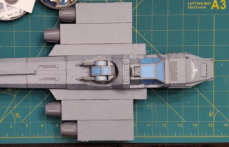
Here are more photos of the wing/engine mounts.
I added additional internal support for added strength. I laminated the outer shell so that the same paint scheme and texture be seen on the inside of the back end (that is open).
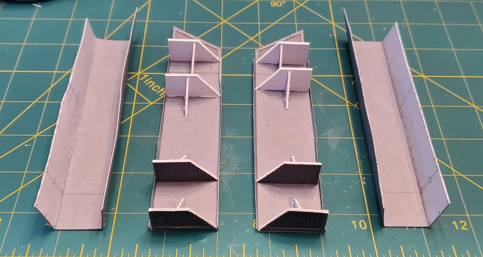
The wing/engine mounts are assembled.
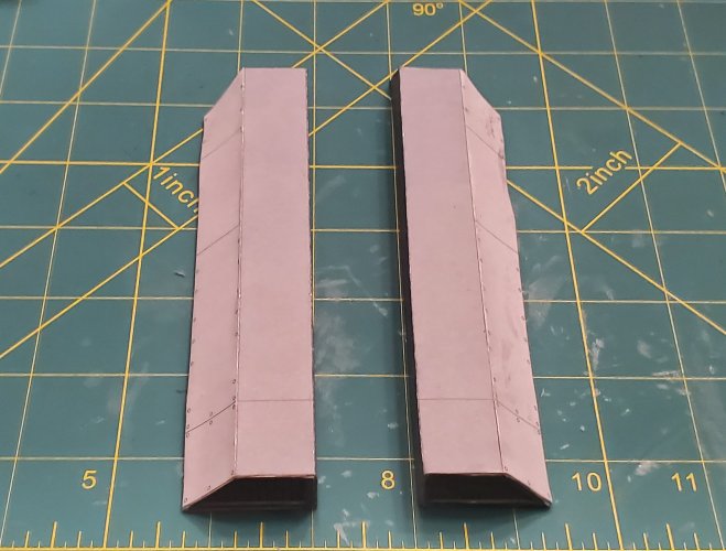
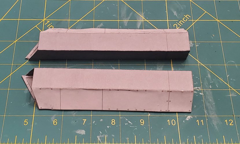
The wing/engine mounts are attached to the fuselage.
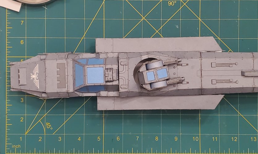
I added additional internal support for added strength. I laminated the outer shell so that the same paint scheme and texture be seen on the inside of the back end (that is open).

The wing/engine mounts are assembled.


The wing/engine mounts are attached to the fuselage.

Thank you sir!I came across your model while browsing, great work, will follow it.
As I have mentioned in previous posts. this template needs work to make it work properly. I will be sharing my notes and photos with the designer.
good idea, I have the same model and can maybe try it for testing purposes, would be interested in the errors.Thank you sir!
As I have mentioned in previous posts. this template needs work to make it work properly. I will be sharing my notes and photos with the designer.
A very interesting model would be the "SULACO" - I think it is about two meters (2.19 yards?) long.
If you are going to try your hand at building the Marauder, I would suggest following the thread that I posted the link to in the beginning of this thread (Here is the link again: https://www.zealot.com/threads/marauder-destroyer.171394/) IT chronicles most (if not all of) the corrections that I made.good idea, I have the same model and can maybe try it for testing purposes, would be interested in the errors.
A very interesting model would be the "SULACO" - I think it is about two meters (2.19 yards?) long.
Jan Rukr was the one who designed the template for the SULACO. Yes, it is 2 meters long. It requires an entire ream of paper and full ink cartridges (I would recommend the XL cartridges). If you do decide to try your hand at building the SULACO, please post a build thread. I would really like to see it.
thank you for the informative answer. If I ever start to build the SULACO, I will of course post a build thread.If you are going to try your hand at building the Marauder, I would suggest following the thread that I posted the link to in the beginning of this thread (Here is the link again: https://www.zealot.com/threads/marauder-destroyer.171394/) IT chronicles most (if not all of) the corrections that I made.
Jan Rukr was the one who designed the template for the SULACO. Yes, it is 2 meters long. It requires an entire ream of paper and full ink cartridges (I would recommend the XL cartridges). If you do decide to try your hand at building the SULACO, please post a build thread. I would really like to see it.
Moving on to the engines now.
I started with the exhaust plates. I printed out enough parts so that I could laminate each layer to 0.5mm.
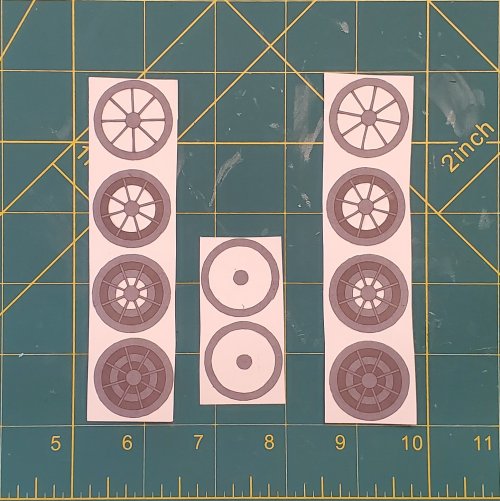
I assembled the layers to give the component a more 'detailed" look.
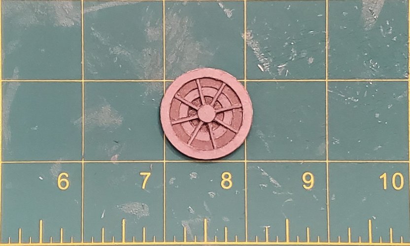
All four exhaust plates are assembled.
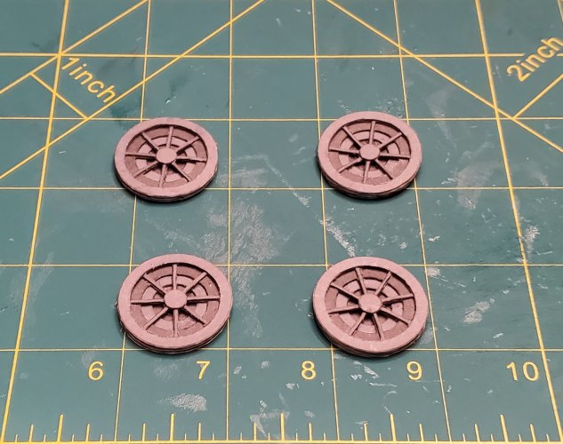
I shaped the exhaust plates so that they would fit inside to the exhaust ports.
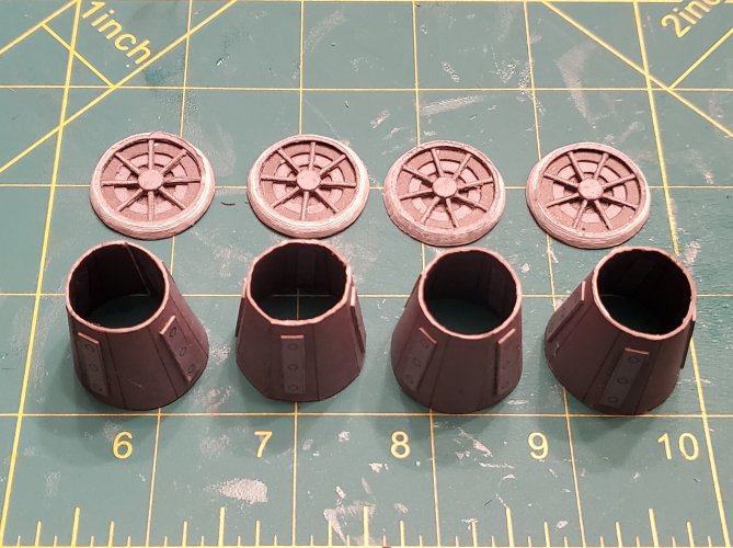
The exhaust port system is assembled.

These are the engines (two small ones that are the outer engines and two larger ones that are the inner engines).
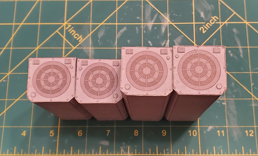
All of the greebling is attached to the smaller engines.
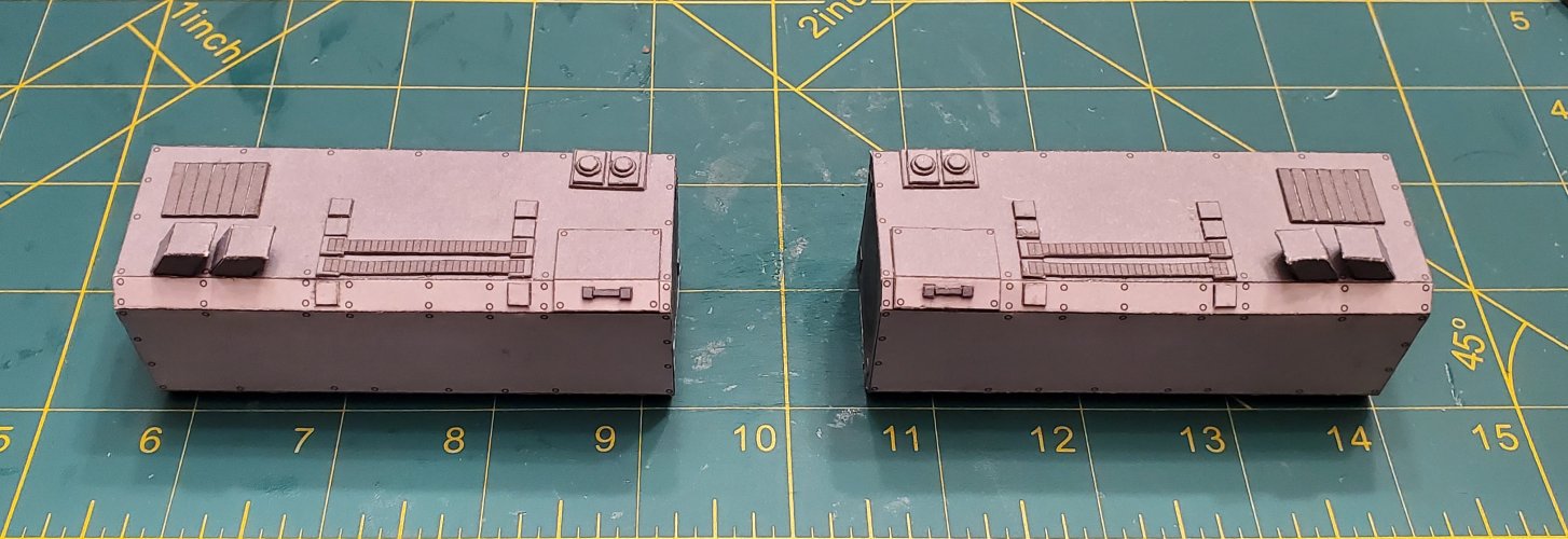
The exhaust port system is attached to all four engines.
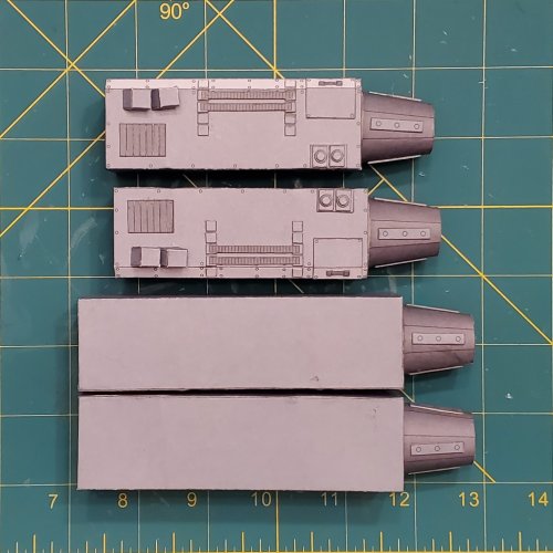
THe engines are attached in place.
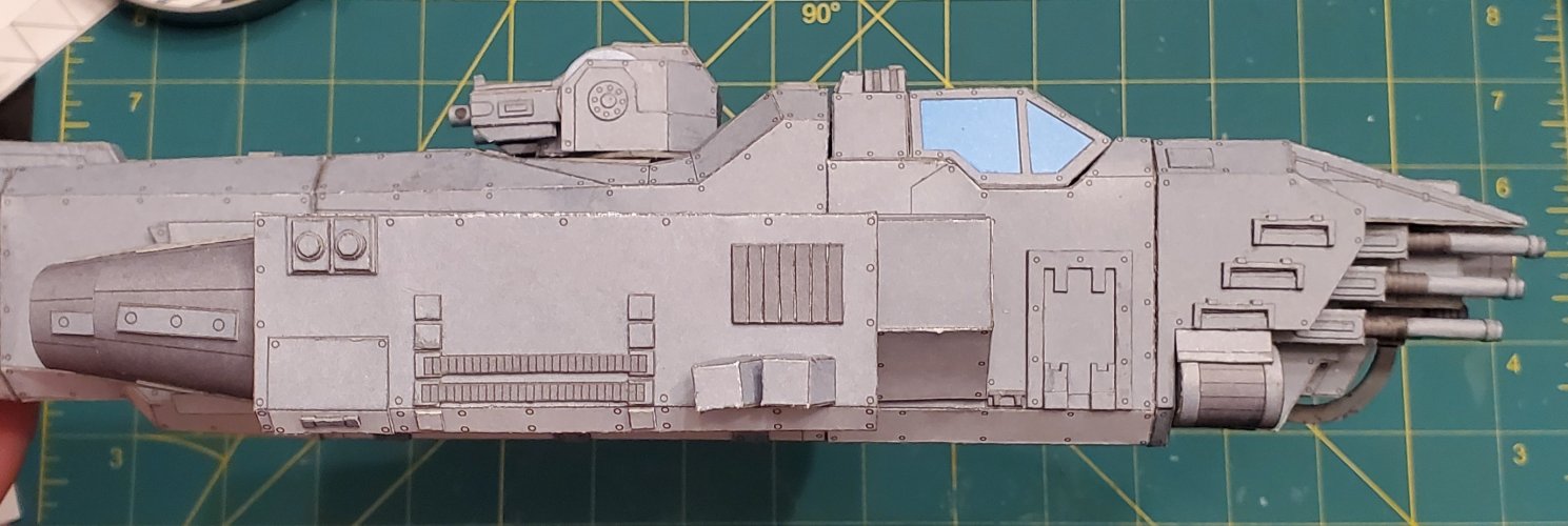
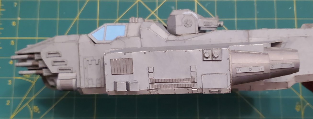
I started with the exhaust plates. I printed out enough parts so that I could laminate each layer to 0.5mm.

I assembled the layers to give the component a more 'detailed" look.

All four exhaust plates are assembled.

I shaped the exhaust plates so that they would fit inside to the exhaust ports.

The exhaust port system is assembled.

These are the engines (two small ones that are the outer engines and two larger ones that are the inner engines).

All of the greebling is attached to the smaller engines.

The exhaust port system is attached to all four engines.

THe engines are attached in place.


They do indeed have a somewhat similar aesthetic.Great job on the thusters. They remind me of TF thrusters..!
Moving on to the engine intake assemblies.
YOU WILL HAVE TO MAKE TWO COPIES OF PARTS SHEETS 11 & 12 TO GET ALL OF THE PARTS (77, 78,79, 79A, 79B, & 80) YOU NEED FOR THESE COMPONENTS! THERE ARE ONLY TWO PER SHEET AND YOU NEED FOUR OF EACH!
Here I had to remake part 78 by hand (It is the "border/frame" piece that wraps around the intake plate), because the part in the kit did not fit properly. I used the same width of the original part 78, then took the measurements of part 77 for length of the panels for part 78. I also added additional width (which is a millimeter wider than the original piece) so that I can fold it in half and have the same texture on both sides (as well as a stronger piece).
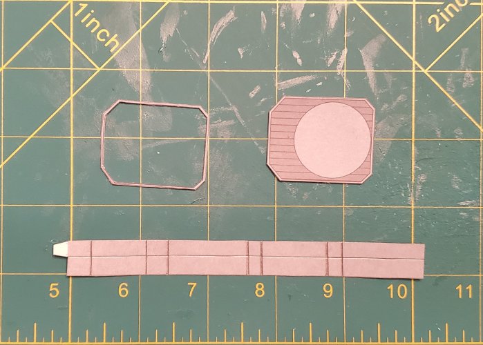
The intake plate is assembled.
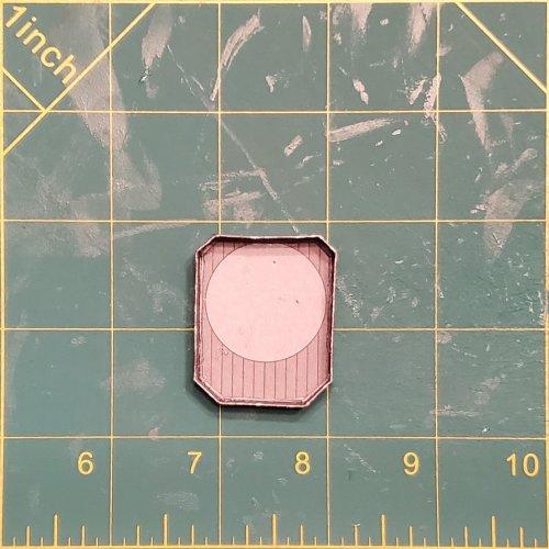
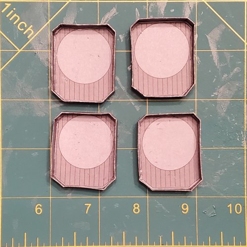
All four plates are assembled.
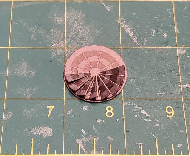
Here is the intake fan. I used the same plate that was used for the exhaust to make the base and "blades". I started applying the "fan blades".
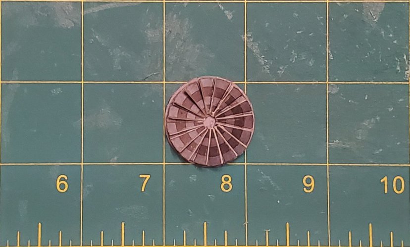
The intake fan is complete
Here are the components for the actual intakes. I printed extra parts to laminate the intake cowling (the yellow ring). I also cut out an extra circle plate (and laminated it to (roughly) 1mm (so that I can use it as a former for the gray ring of the intake.

Started assembling the intake. The circle plate is placed into the gray ring and glued to secure it in place. The intake cowl is placed over the fan assembly and glued in place.
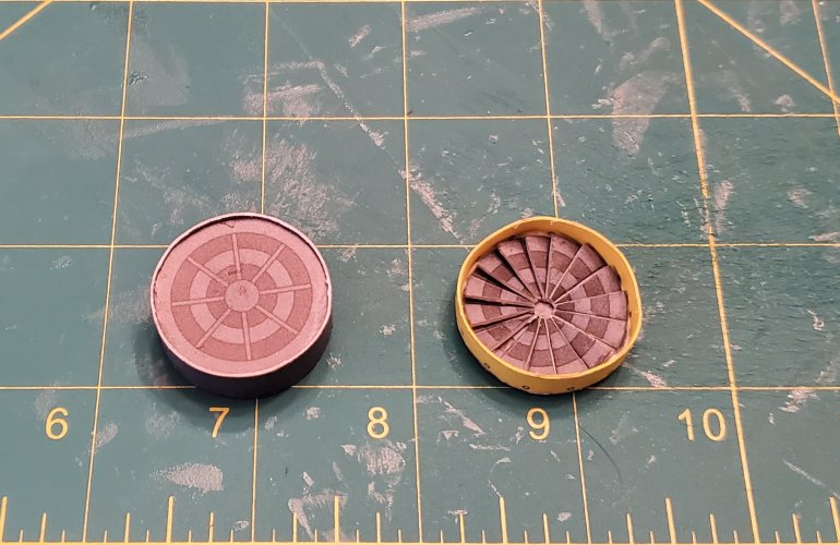
Both components are attached.
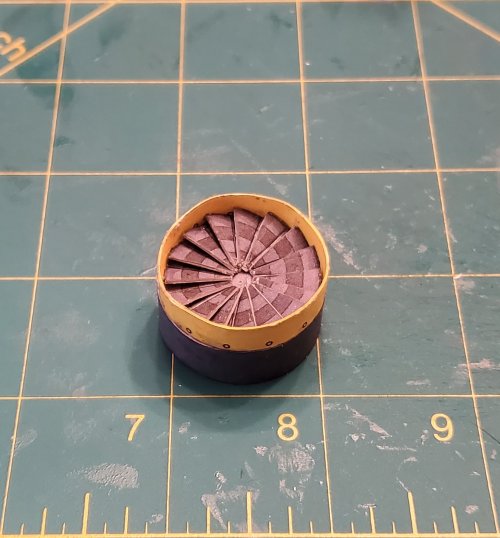
The center fan pin is attached.
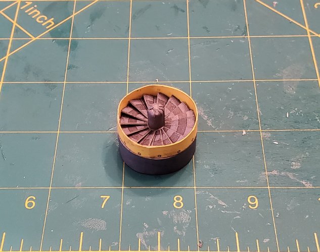
The intake is attached to the intake plate.
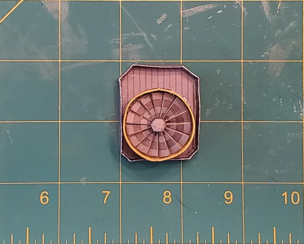
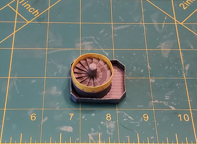
All four intake assemblies are finidhed.
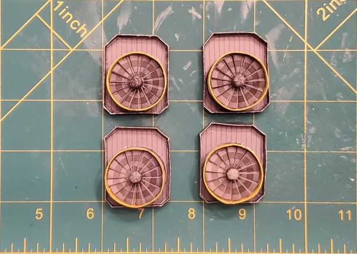
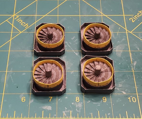
YOU WILL HAVE TO MAKE TWO COPIES OF PARTS SHEETS 11 & 12 TO GET ALL OF THE PARTS (77, 78,79, 79A, 79B, & 80) YOU NEED FOR THESE COMPONENTS! THERE ARE ONLY TWO PER SHEET AND YOU NEED FOUR OF EACH!
Here I had to remake part 78 by hand (It is the "border/frame" piece that wraps around the intake plate), because the part in the kit did not fit properly. I used the same width of the original part 78, then took the measurements of part 77 for length of the panels for part 78. I also added additional width (which is a millimeter wider than the original piece) so that I can fold it in half and have the same texture on both sides (as well as a stronger piece).

The intake plate is assembled.

All four plates are assembled.

Here is the intake fan. I used the same plate that was used for the exhaust to make the base and "blades". I started applying the "fan blades".

The intake fan is complete

Here are the components for the actual intakes. I printed extra parts to laminate the intake cowling (the yellow ring). I also cut out an extra circle plate (and laminated it to (roughly) 1mm (so that I can use it as a former for the gray ring of the intake.

Started assembling the intake. The circle plate is placed into the gray ring and glued to secure it in place. The intake cowl is placed over the fan assembly and glued in place.

Both components are attached.

The center fan pin is attached.

The intake is attached to the intake plate.


All four intake assemblies are finidhed.


That looks VERY nice!  Were the fan blades glued at an angle or did you glue them flat to the base and fold them up in the middle?
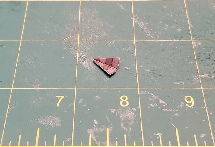
This is a very easy process. I divided the circle into 16 equal parts with pencil lines. Cut the circle into 8 equal wedges. Score the line and fold it slightly. Then layer each blade in place.That looks VERY nice!Were the fan blades glued at an angle or did you glue them flat to the base and fold them up in the middle?
The pic shows the final blad.
