Successful Use of Electromagnets?

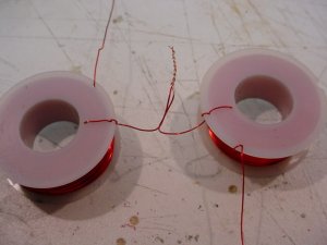
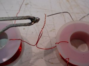
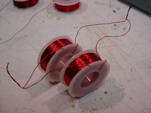
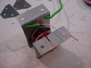
Next we need to solder the coils together, in series... for a 24 volt source. If you are using 12 to 16 volts, the coils need to be soldered together in parallel.

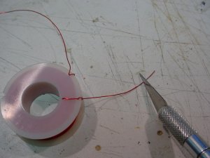
Scrape the red insulation off using a hobby knife, be careful with the sharp blade and the hot soldering iron.

It is important to orient the wires as shown in the photo if you are putting them in series. If you get it backwards, the magnetic fields will cancel out instead of add together. Same thing holds true for a parallel connection. You need to make sure the current is flowing in the same direction in each coil.
 

Attachments

  • MVC-017S.JPG
    MVC-017S.JPG
    40 KB · Views: 77
  • MVC-018S.JPG
    MVC-018S.JPG
    39.9 KB · Views: 74
  • MVC-019S.JPG
    MVC-019S.JPG
    38.2 KB · Views: 76
Time to put the whole thing together now.

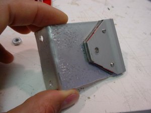
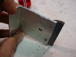
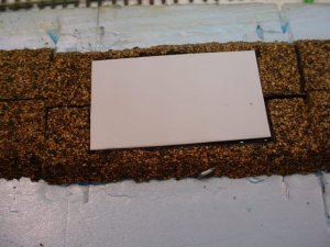
Connect the aluminum mounting brackets to the sideplates, using some 2-56 screws and nuts. A note on the aluminum brackets: I made them so they were a little bit longer than the actual thickness of my layout. This will allow me to make fine adjustements on the height of the magnet sticking through the layout into the roadbed. The very top of the sideplates should be even with the top of the roadbed, well, actually just a touch lower so a piece of plastic can be glued to them so the track can be ballasted. More on that later.
 

Attachments

  • MVC-021S.JPG
    MVC-021S.JPG
    39 KB · Views: 74
  • MVC-022S.JPG
    MVC-022S.JPG
    39.4 KB · Views: 73
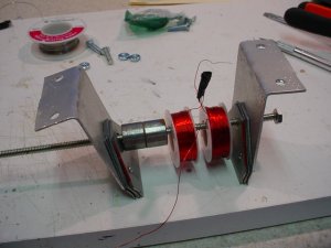
Slide all the pieces onto a piece of 10-24 all thread rod as shown. Tighten it up, making sure to keep the sideplates straight with each other. Also, make sure the coils are oriented properly so the magnetic fields add together instead of cancel out.
 

Attachments

  • MVC-023S.JPG
    MVC-023S.JPG
    39.4 KB · Views: 75
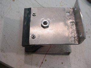
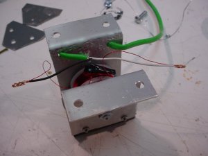
Drill a couple of holes in the aluminum bracket, then thread your feed wire through them, strip them out, and solder them as shown in the photos. Insulate the connections with some electrical tape, and you are done with the uncoupler magnet.
 

Attachments

  • MVC-024S.JPG
    MVC-024S.JPG
    38.8 KB · Views: 75
  • MVC-025S.JPG
    MVC-025S.JPG
    38.8 KB · Views: 75
  • MVC-026S.JPG
    MVC-026S.JPG
    38.2 KB · Views: 75
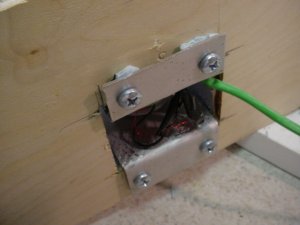
And here is the magnet installed in my test track. You have to cut out a hole so that the magnet fits up through the layout.
 

Attachments

  • MVC-027S.JPG
    MVC-027S.JPG
    40.4 KB · Views: 73
  • MVC-028S.JPG
    MVC-028S.JPG
    38.8 KB · Views: 76
  • MVC-029S.JPG
    MVC-029S.JPG
    40.1 KB · Views: 75
Use the wood screws in the bottom to adjust the height of the magnet. I stuck some blue foam pieces between the plywood and the aluminum bracket to act as a spring to hold the magnet firmly in place.

Hope this is of use to someone. Of course, the dimensions of the aluminum bracket would need to be adjusted for the thickness of your layout.
 
Right on Gary, you got them to work:thumb: . Great tutorial, too. One question, though. Could we wind our on coils? I am curious as to why you didn't do that too. Seems to me that would save some dollars. Not trying to be a wise A, just curious.

Loren
 
hey Loren...

I thought about winding my own, and did see a tutorial on the net where a guy did that. I went as far as buying some magnet wire from Radio Shack, and tried it myself, but it was just a pain and I decided that spending the money was the easiest thing for me. For someone else, winding your own may be the better option. To do it right, you really need to use "magnet wire" as I mentioned, which has a real thin insulation as compared to other types of wire. This concentrates the magnetic field better than wire with thicker insulation. Still, if you had a whole bunch of insulated wire, I guess you could put enough turns on an iron core to make a strong magnet.

If I was going to make my own with some small gauge insulated wire, I would get some 3/8" all thread rod, and put about 4 nuts on it for the core. Then I would put sideplates on the rod on each side, butted up to the nuts, and then put another nut on each side to hold the side plates on. Then I would wind it with the wire. Some experimentation would be needed to figure out how many turns were needed.

On another note, I was reading the instructions from one of the magnets, and it said to use 16 volts AC on the Kadee magnets. But I swear in another set of instructions, it said that 12 volts DC was better. Weird.
 
If you find the article, i would like to see some alternative methods. Even though I have already made six of these, and have the parts on order for a few more, I am sure others would be served by seeing some different methods.
 
The strength of the magnet will depend on the number of turns and the number of amps flowing through those turns. The more turns, the greater the strength. The more amps, the greater the strength. Now, there will be some strength loss depending on how the magnet is constructed = insulation thickness, iron core size and material, air gaps, etc.

Assuming you will use a DC power source, the more turns you have, the higher the resistance is, and the lower the amps will be unless you raise the voltage. So, the number of turns (resistance) and the applied voltage will determine the current (amps) flowing through the magnet.
 
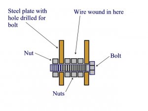
Loren, I thought some more, and if I was going to build my own magnets, I would do something like this. For the bolt, I would use a 3/8" bolt of the desired length. It needs to be threaded for the entire length, or you could use all-thread rod.

I would use some 1/4" thick metal or 3/16" thick for the sideplates, they would need to be drilled for the bolt/rod to go through.

Here is a cross-section of my thoughts. Maybe only 2 nuts in the middle would work, perhaps 3. You could wrap the nuts with some electrical tape if you wanted.

The number of turns of wire would just have to experimented with. An amp meter would be helpful so you would know what is going on.
 

Attachments

  • magneta.jpg
    magneta.jpg
    32.4 KB · Views: 60
Sounds like a good idea.

Some thoughts & changes:

Use a 1/2" bolt and a piece of 1/2" copper pipe for a spacer.
Make sure you use magnet wire. The insulation on plastic covered wire is to thick to allow the number of turns you need.

To space the plates 1/2" apart and have about 1" of windings you have 1/2 sq inch of cross section for wire. Assuming about 50% of the space for air and insulation this gives 1/4 sq inch of wire.

This would give about 1,000 turns of #26 wire. About 420 feet. About 17 ohms. about 3/4 AMP (12v). #24 wire would increase the amp turns by about 50% but would triple the current. SO... I would start with #26 wire. A Drill press with a slow speed to turn it while winding would also be useful.

On ebay 1,500 feet of 26 gauge wire is about $20 + $10 shipping. I am sure you could do a little better but if not that means about $10/coil. Doesn't look like enough savings to make it worth while.

If you want to try your own start with 26 gauge. Don't make the center larger with nuts. That only increases the length of the first turns, increases the resistance, reduces the current & amp turns. Since I doubt a 1/2" bolt would be saturated they won't help increase the flux. Try and get at least 1000 turns. Be willing to do a lot of work to save a couple of dollars - but - to be able to say "I made these"
 
Good thoughts Jim, and thanks for the insight. Using a piece of copper pipe over the bolt instead of the nuts is a good idea. Or, another thought would be to use a 1/4" bolt with 1/4" nuts threaded on, this would decrease the diameter.

As you mention, core saturation is a concern. The Kadee electromagnets use a core that is about 5/8" in diameter. I wonder if they engineered the size based on the minimum amount of cross-sectional area versus needed flux before being saturated?
 
That second link almost makes it look to easy to be true. Would that set-up actually work?

One more question. What is your power source for these things? Is it a simple power pack or is there more to it then that. That always seems to get left out of these tutorials.

Oh. Where would you find a spool of magent wire of that size???
 
I see no reason why that wouldn't work.

Do an internet search on "magnet wire" and you will find places it can be bought.

As for power supplies, you could bite the financial bullet and get one of these 24 volt DC, 2.5 amp supplies:

http://www.factorymation.com/s.nl/it.A/id.4826/.f

Now, you may be able to squeak by with a 1.5 amp supply that is $10 less. Also you may find something like this cheaper elsewhere, and if you have a "electronics surplus" store in your area, try them. Check on E-bay and see what you can find. You need something to convert 120 volt AC into 24 volt DC with 2+ amps.

Other options exist. Perhaps use a 100VA, 120 volt to 24 volt transformer, and get a full-wave bridge rectifier of the proper size (4 amps or so) and build your own supply. It probably wouldn't need a filter capacitor if you were only supplying the electromagnets. If you had relays and what-not used in your magnet control circuit, you may need to filter this supply with a capacitor.

You could do some experimenting with the AC output of a train transformer... the KAdee 309 e-magnet comes with a rectifier and a capacitor, you could use that for a supply, although it would be quite a bit less voltage than 24 volts.

Or, you could use a 12 volt supply and wire the coils in parallel, but this would double the amperage and I would recommend 4+ amps with that.